EP2091167B1 - Vorrichtungen und Verfahren zur optischen Verarbeitung - Google Patents
Vorrichtungen und Verfahren zur optischen Verarbeitung Download PDFInfo
- Publication number
- EP2091167B1 EP2091167B1 EP08019426A EP08019426A EP2091167B1 EP 2091167 B1 EP2091167 B1 EP 2091167B1 EP 08019426 A EP08019426 A EP 08019426A EP 08019426 A EP08019426 A EP 08019426A EP 2091167 B1 EP2091167 B1 EP 2091167B1
- Authority
- EP
- European Patent Office
- Prior art keywords
- light
- pulse
- polarization
- optical
- pulses
- Prior art date
- Legal status (The legal status is an assumption and is not a legal conclusion. Google has not performed a legal analysis and makes no representation as to the accuracy of the status listed.)
- Ceased
Links
Images


Classifications
-
- H—ELECTRICITY
- H04—ELECTRIC COMMUNICATION TECHNIQUE
- H04J—MULTIPLEX COMMUNICATION
- H04J14/00—Optical multiplex systems
- H04J14/08—Time-division multiplex systems
- H04J14/083—Add and drop multiplexing
-
- H—ELECTRICITY
- H04—ELECTRIC COMMUNICATION TECHNIQUE
- H04B—TRANSMISSION
- H04B10/00—Transmission systems employing electromagnetic waves other than radio-waves, e.g. infrared, visible or ultraviolet light, or employing corpuscular radiation, e.g. quantum communication
- H04B10/29—Repeaters
- H04B10/291—Repeaters in which processing or amplification is carried out without conversion of the main signal from optical form
- H04B10/299—Signal waveform processing, e.g. reshaping or retiming
-
- H—ELECTRICITY
- H04—ELECTRIC COMMUNICATION TECHNIQUE
- H04J—MULTIPLEX COMMUNICATION
- H04J14/00—Optical multiplex systems
- H04J14/06—Polarisation multiplex systems
Definitions
- the present invention relates to a device and method for performing signal processing on light in an optical diverging insertion device that divides optical signals used in optical communications and the likes in a time domain.
- Optical fiber communications have developed into ring-type structures and are further developing into mesh-type structures by the wavelength division multiplexing (WDM) technique utilizing the characteristics of optical fiber communications, having started from a system that connects two points with large capacity.
- WDM wavelength division multiplexing
- each node having optical fibers connected thereto preferably has the function to direct signals to different destinations.
- an optical ADM add/Drop Multiplexer
- the electric signal is converted back to an optical signal based on the destination to which the electric signal is directed, and the optical signal is transmitted to the next node.
- a ROADM (Reconfigurable Optical Add/Drop Multiplexer) that can diverge or insert optical signals of desired wavelength has the advantages that optical paths can be arbitrarily set by remote control, and a photonic network that does not depend on bit rates can be constructed. With such a ROADM, a network operation becomes easier, and more flexible construction of photonic networks is realized.
- a ROADM does not have the function to input and output optical signals of the same wavelength at high speed in a time domain, though being flexible in inputting and outputting wavelengths of optical signals.
- a technique for switching optical signal paths in a time domain is disclosed in "All-Optical 80-Gb/s Add-Drop Multiplexer Using Fiber-Based Nonlinear Optical Loop Mirror" (by Ju Han Lee, et al., IEEE PHOTONICS TECHNOLOGY LETTERS, VOL. 17, NO. 4, April 2005 (hereinafter referred to as Reference 2)).
- NOLM Nonlinear loop mirror
- optical signal paths are switched on the time axis by an interference action using control light.
- the NOLM is a high-speed and wide-band device, using a nonlinear effect of the optical fibers. Unlike regular optical fibers for transmitting optical signals, nonlinear fibers having a high nonlinear effect can form a small-sized structure. Also, electricity is not applied in the NOLM.
- US 2006/0051100 A1 teaches an optical switch and an optical waveform monitoring device utilizing said optical switch.
- the optical switch uses a control pulse generator, that in some embodiments can be clocked by the input signal itself, to apply rotation of the polarization of the input signal and optical parametric amplification not to all parts of the signal, but only at a time period during which the signal overlaps or coincides with the control pulse from the pulse generator.
- US 2006/0039642 A1 describes a further optical switch in which electrically controlled reflection surfaces of polarization splitting/combining modules within a light path are used to remove specific peaks of a pulsed light therefrom, allowing injection of equivalently pulsed control light.
- Reference 2 can be clearly distinguished from techniques using electronic circuits. However, it is difficult to maintain stable operations of the interferometer switch using the interference of light in the NOLM, and it is also difficult to increase the switching efficiency due to insertion loss of an optical component or the like. As a result, the optical signal quality is degraded. In a future photonic network that is expected to have a number of nodes for an optical signal to pass through, it is preferable to achieve higher switching efficiency.
- an object of the present embodiment(s) is to increase the switching efficiency in an optical switching operation for switching the output paths of optical signals in a time domain, and avoid degradation of optical signal quality due to switch loss or the like.
- Another object of the present embodiment(s) is to perform stable optical switching operations for diverging and inserting optical signals in a time domain.
- an optical processing device of the invention comprises the features of a light source of a second light that is adapted to output the second light having a pulse in a first polarization state or a second polarization state in synchronization with the timing of a pulse of a first light, the second polarization state being different from the first polarization state; a first nonlinear medium that is adapted to receive pulses of the first and second light, and to control a polarization state of the pulse of the first light in accordance with a polarization state of the second light, using a nonlinear effect; and a separator that is adapted to output the pulse of the first light from the first nonlinear medium selectively to a first output path or a second output path in accordance with the polarization state controlled by the first nonlinear medium, the first nonlinear medium being adapted to use the nonlinear effect to increase the amplitude of the pulse of the first light output selectively to the first output path or the second output path by the separator, the level of the pulse of the
- An optical processing method comprises the steps of outputting a second light having a pulse in a first polarization state or a second polarization state, in synchronization with the timing of a pulse of a first light, the second polarization state being different from the first polarization state; inputting the pulse of the first light and the pulse of the second light to a first nonlinear medium, and controlling a polarization state of the pulse of the first light in accordance with a polarization state of the second light, using a nonlinear effect in the first nonlinear medium; and outputting the pulse of the first light from the first nonlinear medium selectively to a first output path or a second output path in accordance with the polarization state controlled by the first nonlinear medium, the amplitude of the selectively output pulse of the first light being increased by receiving energy of the second light by virtue of the nonlinear effect in the first nonlinear medium, characterized in that the outputting the second light comprises: outputting an optical clock that is substantially in synchronization with the pulse
- the energy of the control light can be transferred to an optical signal by the nonlinear medium. Accordingly, higher optical signal quality can be maintained by increasing the switching efficiency. Also, since a nonlinear effect in an optical domain is utilized, more stable optical switching (the switching of the output paths) can be performed, and a high-speed switching operation with much shorter switching periods can be realized, compared with the conventional technique by which the switching characteristics are affected by the optical interference conditions and the likes.
- Fig. 1 illustrates an optical processing device in accordance with a first embodiment.
- the optical processing device 1 illustrated in Fig. 1 includes optical couplers 2a through 2c, a control light source unit (the light source) 3, a nonlinear medium (the first nonlinear medium) 4, a wavelength filter 5, a polarizer 6, and an optical phase shifter 7.
- the optical processing device can switch output paths on a bit-time basis, with respect to an optical signal of wavelength ⁇ SIG to be input.
- the optical signal to be input is described as a RZ intensity-modulated pulse, but an optical signal modulated by some other method may also be used.
- the optical coupler 2a outputs a part of the input optical signal (the first light) to the control light source unit 3, and outputs the rest of the optical signal to the optical coupler 2b connected to the nonlinear medium 4.
- a polarization controller (the first polarization controller) 8a may be provided.
- the control light source unit 3 is a control light source that outputs a control light (the second light) pulse that is substantially synchronized with the optical signal pulse. And the control pulse has a light pulse in a first polarization state or a second polarization state different from the first polarization state in accordance with the pulse timing of the optical signal pulse.
- the control light source unit 3 outputs a clock pulse ( ⁇ CON in optical wavelength) having light pulses in one of the first and second polarization states that are perpendicular to one another and are arranged on a time axis, respectively.
- the clock pulse is used as a control light pulse at the nonlinear medium 4 in the later stage to control the polarization state of the input optical signal based on an optical parametric effect as a third-order nonlinear optical effect.
- the control light source unit 3 includes an optical pulse generator 3a, an optical coupler 3b, a nonlinear medium (the second nonlinear medium) 3c, and a wavelength filter 3d.
- the optical pulse generator 3a outputs an optical clock of the wavelength ⁇ CON substantially synchronized with clock components extracted from the optical signal from the optical coupler 2a.
- the optical pulse generator 3a also outputs a light pulse of wavelength ⁇ SEL that is different from ⁇ CON.
- the light pulse ⁇ SEL is polarization-state selecting light.
- the light pulse ⁇ SEL forms an extinction state in a time domain where the polarization state of the control light pulse output from the control light source unit 3 itself should be put into a certain polarization state, and also forms a rising state in a time domain where the polarization state of the control light pulse should be put into another polarization state.
- the optical pulse generator 3a is a clock light source that outputs an optical clock substantially synchronized with the optical signal pulse.
- the optical pulse generator 3a is also a polarization-state selecting light source that outputs the polarization-state selecting light having each pulse rise in synchronization with the pulse timing of the control light pulse in either one of the first and second polarization states among the clock pulses forming the optical clock.
- the polarization-state selecting light ⁇ SEL illustrated in Fig. 1 is in a rising state in synchronization with the pulse timing of the clock pulses that are second and fifth clock pulses (from the right-hand side) of the clock pulses forming the optical clock.
- the polarization-state selecting light ⁇ SEL is in an extinction state in synchronization with the pulse timing of the other clock pulses.
- the optical coupler 3b combines the optical clock and the polarization-state selecting light ⁇ SEL from the optical pulse generator 3a in polarization states having different polarization angles from each other by approximately 45 degrees.
- the combined light has a polarization angle of -45 degrees with respect to the optical clock to be input to the nonlinear medium 3c, and has a polarization approximately vertical with respect to the polarization-state selecting light ⁇ SEL.
- the optical pulse generator 3a can output a control light pulse forming the optical clock and the polarization-state selecting light ⁇ SEL having such a relationship in polarization direction with respect to each other.
- polarization controllers 8b and 8c for adjusting the polarization states of the optical clock and the polarization-state selecting light ⁇ SEL may be provided on the optical paths between the optical pulse generator 3a and the optical coupler 3b, if necessary.
- the nonlinear medium (the second nonlinear medium) 3c receives the optical clock and the polarization-state selecting light ⁇ SEL from the optical pulse generator 3a via the optical coupler 3b, and generates a clock pulse string (of the optical wavelength ⁇ CON) through polarization rotation caused by an optical Kerr effect, for example.
- a clock pulse string of the optical wavelength ⁇ CON
- light pulses of the first and second polarization states perpendicular to each other are arranged on the time axis.
- Nonlinear fiber optics 4th edition, Academic press, 2007 “ discloses the principles of polarization rotation.
- first light equivalent to the optical clock
- second light equivalent to the polarization-state selecting light ⁇ SEL
- XPM cross phase modulation
- the time domain where the polarization-state selecting light ⁇ SEL to be input to the nonlinear medium 3c is in an extinction state does not overlap the optical clock in terms of time. Accordingly, the polarization state of the optical clock does not rotate, and the optical clock in this time domain is output while maintaining the same polarization state as that of the input time (the polarization state having a polarization angle of -45 degrees).
- the time domain where the polarization-state selecting light ⁇ SEL is in a rising state overlaps the optical clock in terms of time. Accordingly, the polarization state of the optical clock in this time domain rotates, and the optical clock in a polarization state having a polarization angle of approximately 45 degrees is output as a result.
- the nonlinear coefficient and the interaction length of the nonlinear medium 3c, and the intensity of the optical clock to be input to the nonlinear medium 3c are set so that the polarization angle of the optical clock (having a polarization state of approximately 45 degrees) output from the nonlinear medium 3c in the time domain having the polarization rotation is substantially at a right angle with respect to the optical clock (having a polarization state of approximately -45 degrees) in the time domain that has ceased polarization rotation.
- the optical filter 3d removes the wavelength components ( ⁇ SEL) of the polarization-state selecting light from the light output from the nonlinear medium 3c, and lets the components of the optical clock wavelength ( ⁇ CON) pass as the above described control light pulse.
- the control light pulse is output to the nonlinear medium 4 via the optical coupler 2b.
- a polarization controller (the second polarization controller) 8d may be further provided.
- the polarization controller 8d controls the control light pulse to have a desired polarization state.
- the nonlinear medium 3c may be realized with the use of a step index optical fiber, a nonlinear optical fiber that is a holey fiber having cavities in its cross section and has a nonlinear coefficient improved with an increase in nonlinear refractive index through a reduction of the core cross-sectional area or an addition of germanium or the like, a nonlinear optical fiber that has a main component with an extremely high nonlinear refractive index such as chalcogenide, or a photonic crystal fiber that has a coefficient improved by enclosing light by virtue of a bandgap effect.
- a step index optical fiber a nonlinear optical fiber that is a holey fiber having cavities in its cross section and has a nonlinear coefficient improved with an increase in nonlinear refractive index through a reduction of the core cross-sectional area or an addition of germanium or the like
- a nonlinear optical fiber that has a main component with an extremely high nonlinear refractive index such as chalcogenide
- the optical signal that inputs to the nonlinear medium 4 through the optical coupler 2b is in an approximately horizontal linear polarization state as illustrated in Fig. 1 , for example.
- the control light pulse forms a pulse string having light pulses arranged on the time axis.
- Each of the light pulses has one of two polarization states (one of the first and second polarization states).
- the two polarization states are polarization angles of -45 degrees and 45 degrees with respect to the horizontal direction, and are perpendicular to each other.
- the nonlinear medium (the first nonlinear medium) 4 receives the above optical signal pulse and the control light pulse.
- the nonlinear medium 4 controls the polarization state of the optical signal in accordance with the polarization state of the control light pulse.
- the optical signal pulses receive the energy of the control light pulse, the optical signal is amplified.
- the polarizer 6 in the later stage can divide the input optical signal pulses into different output paths.
- the control light pulse from the control light source unit 3 has a polarization state that is perpendicular to the optical signal to be divided into the output paths at the polarizer 6 in the later stage.
- the operation to increase the amplitude while controlling the polarization state is based on a third-order nonlinear optical effect such as an optical parametric effect.
- a third-order nonlinear optical effect such as an optical parametric effect.
- a control light pulse that is synchronized with the input optical signal pulse and has the first or second polarization state is generated in accordance with the output path to be set for each light pulse in the optical signal pulse string.
- the optical signal pulse to be input to the nonlinear medium 4 has a polarization state controlled so as to conform to the polarization state of the control light pulse in each time domain.
- the optical signal pulse that is output from the nonlinear medium 4 is controlled to have a linear polarization state of -45 degrees.
- the optical signal pulse is controlled to have a linear polarization state of 45 degrees.
- the nonlinear medium 4 has ⁇ CON as the zero-dispersion wavelength ⁇ 0.
- the nonlinear medium 4 may be a step index optical fiber, a nonlinear optical fiber that is a holey fiber having cavities in its cross section and has a nonlinear coefficient improved with an increase in nonlinear refractive index through a reduction of the core cross-sectional area or an addition of germanium or the like, a nonlinear optical fiber that has a main component with an extremely high nonlinear refractive index such as chalcogenide, a photonic crystal fiber that has a coefficient improved by enclosing light by virtue of a bandgap effect, or a nonlinear waveguide utilizing a silicon photonics technique, or the like.
- the nonlinear medium 4 is not limited to those materials.
- the optical filter 5 transmits the wavelength components ( ⁇ SIG) of optical signal pulses of the light output from the nonlinear medium 4, and also removes the components other than the wavelength components of the optical signal pulses such as the wavelength components ( ⁇ CON) of the control light pulse.
- the optical filter 5 then outputs the remaining components to the polarizer 6.
- the optical filter 5 may be a filter formed by depositing a dielectric multi-layer film or may be an optical fiber Bragg grating having a periodic structure at the core of an optical fiber, for example. However, the optical filter 5 is not limited to those structures.
- the polarizer 6 is a separator that outputs optical signal pulse from the nonlinear medium 4 selectively to a first output path or a second output path in accordance with the polarization state controlled by the nonlinear medium 4. More specifically, each optical signal pulse controlled to have the linear polarization state of -45 degrees by the nonlinear medium 4 is output to the first output path P1. Each optical signal pulse controlled to have the linear polarization state of 45 degrees by the nonlinear medium 4 is output to the second output path P2.
- the polarizer 6 may be formed with a polarization prism having a prism pair bonded thereto, so that polarized components perpendicular to each other can be simultaneously output to different output paths, for example.
- the polarization state of input optical signal (horizontal-direction linear polarization) is controlled, so that the light pulses to be output through the first output path P1 (the first, third, fourth, and sixth light pulses from the right-hand side in Fig. 1 ) of the optical signal pulse string SIG to be output from the optical filter 5 are controlled to have the polarization angle of -45 degrees, while the light pulses to be output through the second output pathP2 (the second and fifth light pulses from the right-hand side in Fig. 1 ) are controlled to have the polarization angle of 45 degrees, as illustrated in Fig. 1 .
- the polarization state of each optical signal pulse can be controlled by the control light pulse output from the control light source unit 3.
- the polarizer 6 can be designed as an optical switch that switches the output path between the first output path P1 and the second output path P2 for each pulse of the optical signal pulse string that is input through one input port. If the first output path is set as a through port, and the second output path is set as a drop port, the light pulses to be separately output from the second output path P2 as the drop port can be selected from the optical signal pulses by the control light pulse.
- the optical signal amplifying effect can be provided as well as the polarization state control for controlling the switching of the output paths. Accordingly, the switching efficiency that is the ratio in intensity between the input optical signal and the optical signal obtained after the output path switching can be improved (can be made 1 or higher, for example). Thus, the switching efficiency determined by the ratio between the input signal intensity and the output signal intensity can be made much higher than the switching efficiency in a conventional case.
- the control light is required to have relatively high intensity. Therefore, as illustrated in Fig. 1 , the control light source unit 3 may further include an optical amplifier 9 that increases the amplitude of the control light pulse output from the nonlinear medium 3c. In the example illustrated in Fig. 1 , the optical amplifier 9 is provided between the optical filter 3d and the polarization controller 8d.
- the switching efficiency is set at 1 or higher by the optical signal amplifying effect.
- the switching efficiency may be lower than 1 relative to the first light pulse, as long as the level of each first light pulse that is output to the first output path P1 or the second output path P2 by the polarizer 6 using a nonlinear effect can be compensated by receiving the energy of the second light.
- the optical phase shifter 7 delays and adjusts the insertion timing of light pulses to be inserted through the downstream optical transmission path to the empty pulse positions on the time axis in synchronization with the timing for not outputting light pulses from the polarizer 6 through the first output path P1.
- the light pulses having the insertion timing adjusted by the optical phase shifter 7 are combined with the optical signal output from the polarizer 6 through the first output path P1 by the optical coupler 2c. In this manner, light pulses from the optical phase shifter 7 are inserted in the empty timing positions in the optical pulse string, and are output to the downstream optical transmission path.
- the optical phase shifter 7 and the optical coupler 2c form a pulse inserting unit that inserts light pulses to the optical signal pulses output through the first output path P1, in synchronization with the optical signal pulses separated by the polarizer 6 and output through the second output path P2.
- the control light source unit 3 outputs a control light pulse that is substantially in synchronization with the input optical signal pulse, and has light pulses in the first polarization state or the second polarization state different from the first polarization state.
- the control light source unit 3 outputs the control light pulse in synchronization with the pulse timing of the optical signal pulse.
- the control light pulse is a linearly-polarized optical clock that has polarization states perpendicular to each other, like the signal (optical signal pulse) to pass through the polarizer 6 or to be diverged at the polarizer 6 in the later stage.
- optical signal pulse and the control light pulse in synchronization with each other are input to the nonlinear medium 4.
- the polarization states of the linearly-polarized optical signal and control light are adjusted at approximately 45 degrees (or approximately -45 degrees) with respect to each other.
- the polarization state of the optical signal pulse can be controlled in accordance with the polarization state of the control light pulse by virtue of the nonlinear effect at the nonlinear medium 4.
- the polarization directions of the diverged signal directed to the second output path P2 and the non-diverged signal directed to the first output path P1 become approximately perpendicular to each other.
- optical signals linearly-polarized in the horizontal direction rotate approximately 45 degrees and approximately -45 degrees, respectively.
- the energy of the control light is transferred to the optical signal, so as to increase the amplitude of the optical signal.
- the diverged optical signal and the non-diverged optical signal perpendicular to each other are separated from each other by the polarizer 6. If necessary, an insertion optical signal can be input to the empty time domains in the non-diverged optical signal through the optical phase shifter 7 and the optical coupler 2c.
- the nonlinear medium 4 can transfer the energy of the control light to the optical signal. Accordingly, the intensity of the optical signal after the switching of the output paths can be made higher than the intensity of the optical signal observed at the time of the input, unlike the intensity of an optical signal that becomes lower due to insertion loss of an optical component or the like at a conventional optical switch. Thus, high optical signal quality can be maintained by increasing the switching efficiency to 1 or more. Furthermore, it is possible to realize a high-speed switch that is not limited by the number of optical divergence insertion nodes the optical signal passes through and is unbounded by the restrictions on the electronic-circuit operation speed. Thus, the construction of a photonic network with high flexibility and operability can be sped up.
- control light that has the polarization state corresponding to an output path as a switching destination of the polarizer 6 for each pulse is generated, so that the output paths can be switched based on the pulse width of the control light.
- high-speed switching with much smaller switching periods can be performed.
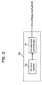
- Fig. 2 illustrates an optical processing device 1A in accordance with a second embodiment.
- the optical processing device 1A illustrated in Fig. 2 differs from the optical processing device of the first embodiment in a control light pulse to be output from a control light source unit 3A, and a separator that divides the optical signal output from the nonlinear medium 4 into components to be output to the first and second output paths.
- the other aspects of this embodiment are the same as those of the first embodiment.
- the same reference numerals as those in Fig. 1 denote approximately the same components as those illustrated in Fig. 1 .
- control light source unit 3 illustrated in Fig. 1 the polarization states of light pulses of an input optical signal as a horizontal-direction linearly-polarized signal to be output to the first and second output paths P1 and P2 are rotated at the nonlinear medium 4.
- control light source unit 3A illustrated in Fig. 2 outputs a control light pulse having such a polarization state that the polarization state of a light pulse to be output to the second output path P2 is rotated at the nonlinear medium 4, but the polarization state of a light pulse to be output to the first output path P1 is not rotated.
- the control light pulse corresponding to an optical signal pulse to be output to the first output path P1 has approximately the same horizontal linear polarization as the optical signal pulse, but the control light pulse corresponding to an optical signal pulse to be output to the second output path P2 has linear polarization tilted approximately 45 degrees.
- the polarization state of the control light corresponding to the optical signal to be diverged to the second output path P2 is a linear polarization state, and is at approximately 45 degrees with respect to the polarization direction of the linear polarization of the control light corresponding to the non-diverged optical signal.
- the optical pulse generator 3a' of the control light source unit 3A is a clock light source and is a polarization-state selecting light source like the optical pulse generator 3a illustrated in Fig. 1 , but differs from the optical pulse generator 3a in the polarization states of the optical clock ⁇ CON and the polarization-state selecting light ⁇ SEL at the stage on the input side of the optical coupler 3b.
- the optical clock to be input to the optical coupler 3b illustrated in Fig. 2 has approximately horizontal linear polarization like the above described optical signal
- the control light pulse forming the polarization-state selecting light ⁇ SEL has linear polarization of a polarization angle of approximately 45 degrees relative to the optical clock.
- the optical pulse generator 3a' can output the optical clock and the control light pulse forming the polarization-state selecting light ⁇ SEL having the above polarization-direction relationship.
- polarization controllers 8b' and 8c' adjusting the polarization states of the optical clock and the polarization-state selecting light ⁇ SEL may be provided on the optical paths between the optical pulse generator 3a' and the optical coupler 3b, if necessary.
- the nonlinear medium (the second nonlinear medium) 3c receives the optical clock and the polarization-state selecting light ⁇ SEL from the optical pulse generator 3a' via the optical coupler 3b, and outputs the optical clock and the polarization-state selecting light ⁇ SEL in the following manner, using polarization rotation caused by an optical Kerr effect, for example.
- the polarization-state selecting light ⁇ SEL is in a rising state
- the polarization state of the light pulses forming the optical clock ⁇ CON rotates to have linear polarization at an inclination angle of 45 degrees (the second polarization state).
- the polarization-state selecting light ⁇ SEL is in an extinction state
- the polarization state of the light pulses of the optical clock ⁇ CON remains unchanged (the first polarization state).
- control light source unit 3a' can output a control light pulse that is in synchronization with the optical signal, and has light pulses arranged on the time axis.
- the light pulses of the control light pulse include light pulses in the approximately horizontal linear polarization state, which is the first polarization state, and light pulses having the linear polarization rotated approximately 45 degrees, which is the second polarization state.
- the optical signal pulse to be input in synchronization with the control light pulse in the first polarization state is not subjected to the polarization rotation by an optical parametric effect or the like.
- the optical signal pulse receives the energy of the control light pulse. Accordingly, the optical signal pulse to be output can be amplified (or the level of the optical signal pulses is compensated).
- the optical signal pulse to be input in synchronization with the control light pulse in the second polarization state is subjected to the polarization rotation by an optical parametric effect or the like, as in the case of the first embodiment.
- the optical signal pulse to be output can be amplified.
- a diverging unit 6a and first and second polarizers 6b and 6c are provided as a structure serving as a separator that outputs the optical signal pulse from the nonlinear medium 4 via the optical filter 5 selectively to the first output path P1 or the second output path P2 in accordance with the polarization state controlled by the nonlinear medium 4.
- the diverging unit (the divider) 6a divides the optical signal pulse from the nonlinear medium 4 into two portions.
- the first polarizer 6b allows the optical signal pulse component having the first polarization state to pass, but shuts off the optical signal pulse component having the second polarization state.
- the second polarizer 6c allows the optical signal pulse component having the second polarization state to pass, but shuts off the optical signal pulse component having the first polarization state.
- the polarization direction of the optical signal pulse to be guided to the second output path P2 from the optical filter 5 is a 45-degree polarization direction. Therefore, the first polarizer 6b has its transmission face adjusted so that the transmission direction becomes perpendicular to the 45-degree polarization direction, and the light polarized in the approximately -45-degree polarization direction is transmitted. Meanwhile, the polarization direction of optical signal pulse to be guided to the first output path P1 from the optical filter 5 is the horizontal direction. Therefore, the first polarizer 6b has the transmission face adjusted in the same manner as above, so that the corresponding polarization-direction component of the optical signal pulse can be transmitted from the first polarizer 6b.
- the polarization direction of the optical signal pulse to be guided to the first output path P1 from the optical filter 5 is the horizontal direction. Therefore, the second polarizer 6c has its transmission face adjusted so that the transmission direction becomes perpendicular to the horizontal direction, and the light polarized in the approximately vertical direction is transmitted. Meanwhile, the polarization direction of optical signal pulse to be guided to the second output path P2 from the optical filter 5 is a 45-degree polarization direction. Therefore, the second polarizer 6c has the transmission face adjusted in the same manner as above, so that the corresponding polarization-direction component of the optical signal pulse can be transmitted from the second polarizer 6c.
- the optical signal pulse transmitted through the first polarizer 6b can be set as the light pulse to be output through the first output path P1
- the optical signal pulse transmitted through the second polarizer 6c can be set as the light pulse to be output through the second output path P2.
- polarization controllers 8f and 8g are provided in the stage on the input side of the polarizers 6b and 6c, so that the extinction ratio between the diverged optical signal and the non-diverged optical signal can be set at a high value.
- the first light as an optical signal and the second light as the control light are input to the nonlinear medium 4.
- the polarization states of the first light and the second light are substantially the same linear polarization states in a case of non-divergence (guided to the first output path P1), but the first light and the second light have linear polarization states at 45 degrees with respect to each other in a case of divergence (guided to the second output path P2).
- the polarization of the optical signal is rotated to have the second polarization state in the nonlinear medium 4, and the amplitude of the optical signal is increased.
- the non-diverged optical signal has the same polarization state as the control light. Therefore, the non-diverged optical signal has amplitude three times as high as the amplitude of the diverged optical signal.
- the optical signal having the control light wavelength removed by the optical filter 5 is divided into two portions by the diverging unit 6a.
- the transmission faces of the first polarizer 6b and the second polarizer 6c are adjusted so that the first polarizer 6b does not allow the diverged optical signal to pass, and the second polarizer 6c does not allow the non-diverged optical signal to pass. In this manner, the optical signal can be divided.
- the second embodiment can achieve the same effects as those of the first embodiment.
- the control light source unit may include a CW (Continuous Wave) light source 3e that outputs continuous light, and a polarization controller 3f that performs polarization control so that the continuous light from the CW light source 3e has a first polarization state or a second polarization state different from the first polarization state (having a 90-degree polarization angle difference, for example). More specifically, at the polarization controller 3f, the input continuous light is controlled to have the first polarization state in synchronization with the optical signal pulse to be guided to the first output path, and to have the second polarization state in synchronization with the optical signal pulse to be guided to the second output path. In this manner, the control light source units 3 and 3A illustrated in Figs. 1 and 2 can be replaced with the control light source unit 3B. Although this structure restricts the switch response speed to the electronic-circuit operation speed, stable control light can be supplied.
- CW Continuous Wave
Landscapes
- Engineering & Computer Science (AREA)
- Computer Networks & Wireless Communication (AREA)
- Signal Processing (AREA)
- Physics & Mathematics (AREA)
- Electromagnetism (AREA)
- Optical Modulation, Optical Deflection, Nonlinear Optics, Optical Demodulation, Optical Logic Elements (AREA)
Claims (15)
- Optische Prozessierungsvorrichtung (1), umfassend:eine Lichtquelle (3) eines zweiten Lichts, die dafür ausgelegt ist, das zweite Licht mit Impulsen in einem ersten Polarisationszustand und Impulsen in einem zweiten Polarisationszustand synchron mit der Zeitvorgabe eines Impulses (λSIG) eines ersten Lichtes auszugeben, wobei sich der zweite Polarisationszustand vom ersten Polarisationszustand unterscheidet;ein erstes nicht-lineares Medium (4), das dafür ausgelegt ist, Impulse des ersten und zweiten Lichtes aufzunehmen und einen Polarisationszustand der Pulse des ersten Lichtes gemäß einem Polarisationszustand der Impulse des zweiten Lichtes unter Verwendung eines nicht-linearen Effektes zu steuern; undeinen Separator (6), der ausgelegt ist, die Impulse des ersten Lichtes aus dem ersten nicht-linearen Medium (4) selektiv an einen ersten Ausgabepfad oder einen zweiten Ausgabepfad gemäß den Polarisationszuständen auszugeben, welche durch das nicht-lineare Medium gesteuert sind,wobei das erste nicht-lineare Medium (4) dafür ausgelegt ist, den nicht-linearen Effekt zu verwenden, um die Amplitude des Impulses des durch den Separator (6) selektiv an den ersten Ausgabepfad und den zweiten Ausgabepfad ausgegebenen ersten Lichts zu vergrößern, wobei der Pegel der Impulse des ersten Lichts Energie des zweiten Lichts aufnimmt,wobei die Lichtquelle (3) des zweiten Lichts umfasst:eine Taktlichtquelle, die dafür ausgelegt ist, einen optischen Takt (λCON) auszugeben, der im Wesentlichen synchron zu den Impulsen des ersten Lichts ist;eine Polarisationszustands-Auswahl-Lichtquelle, die ausgelegt ist, Polarisationszustands-Auswahllicht mit einem Impulsanstieg (λSEL) synchron zur Impulszeitgabe zum Auswählen des ersten oder zweiten Polarisationszustands aus Taktimpulsen des optischen Takts auszugeben; undein zweites nicht-lineares Medium (3c), das ausgelegt ist, einen optischen Takt aus der Taktlichtquelle und das Polarisationszustands-Auswahllicht aus der Polarisationszustand-Auswahllichtquelle aufzunehmen und einen optischen Takt als die Impulse des zweiten Lichts mit einem Taktimpuls des ersten oder des zweiten Polarisationszustandes unter Verwendung eines nicht-linearen Effekts auszugeben.
- Optische Prozessierungsvorrichtung (1) gemäß Anspruch 1, wobei die ersten und zweiten Polarisationszustände zwei lineare Polarisationszustände sind, die fast lotrecht zueinander sind.
- Optische Prozessierungsvorrichtung (1) gemäß Anspruch 2, wobei der Separator (6) mit einem Polarisator ausgebildet ist, und ausgelegt ist, eine Impulskomponente des ersten Lichtes, das gesteuert ist, den ersten Polarisationszustand aufzuweisen, durch das erste nicht-lineare Medium, an den ersten Ausgabepfad auszugeben, und eine Impulskomponente des ersten Lichts, das gesteuert ist, den zweiten Polarisationszustand aufzuweisen, an den zweiten Ausgabepfad auszugeben.
- Optische Verarbeitungsvorrichtung (1) gemäß Anspruch 1, wobei die ersten und zweiten Polarisationszustände zwei lineare Polarisationszustände sind, die ungefähr 45 Grad in Bezug aufeinander aufweisen.
- Optische Prozessierungsvorrichtung (1) gemäß Anspruch 4, wobei der Separator (6) umfasst:einen Teiler (6a), der dafür ausgelegt ist, den ersten Lichtimpuls aus dem ersten nicht-linearen Medium in Zwei zu teilen;einen ersten Polarisator (6b), der dafür ausgelegt ist, einer Impulskomponente des ersten Lichtes, die den ersten Polarisationszustand aufweist, zu gestatten, zu passieren, und eine Impulskomponente des ersten Lichts mit dem zweiten Polarisationszustand auszuschließen, wobei die Impulskomponenten des ersten Lichts von einem der geteilten Anteile des Impulses des ersten Lichts sind; undeinen zweiten Polarisator (6c), der dafür ausgelegt ist, eine Impulskomponente des ersten Lichtes mit dem zweiten Polarisationszustand zu gestatten, zu passieren, und eine Impulskomponente des ersten Lichts mit dem ersten Polarisationszustand auszuschließen, wobei die Impulskomponenten des ersten Lichts von der anderen der geteilten Anteile des Impulses des ersten Lichtes sind.
- Optische Prozessierungsvorrichtung (1), umfassend:eine Lichtquelle (1) eines zweiten Lichts, die dafür ausgelegt ist, das zweite Licht mit Impulsen in einem ersten Polarisationszustand und Impulsen in einem zweiten Polarisationszustand synchron zu der Zeitvorgabe eines Impulses (λSIG) eines ersten Lichts auszugeben, wobei der zweiten Polarisationszustand sich vom ersten Polarisationszustand unterscheidet;ein erstes nicht-lineares Medium (4), das dafür ausgelegt ist, Impulse des ersten und zweiten Lichts aufzunehmen und einen Polarisationszustand der Impulse des ersten Lichtes in Übereinstimmung mit einem Polarisationszustand der Impulse des zweiten Lichtes unter Verwendung eines nicht-linearen Effekts zu steuern; undeinen Separator (6), der ausgelegt ist, die Impulse des ersten Lichtes aus dem ersten nicht-linearen Medium (4) selektiv an einen ersten Ausgabepfad oder einen zweiten Ausgabepfad gemäß den durch das erste nicht-lineare Medium gesteuerten Polarisationszuständen auszugeben,wobei das erste nicht-lineare Medium (4) dafür ausgelegt ist, den nicht-linearen Effekt zu verwenden, um einen Pegel des Impulses des, aus dem ersten Ausgabepfad und dem zweiten Ausgabepfad durch den Separator (6) ausgegebenen ersten Lichts zu kompensieren, wobei der Pegel der Impulse des ersten Lichts Energie des zweiten Lichts empfängt,wobei die Lichtquelle des zweiten Lichts umfasst:eine Lichtquelle; undeinen Polarisationsmodulator (3b, 3c), der ausgelegt ist, einen Polarisationszustand des aus der Lichtquelle emittierten Lichtes zu modulieren, wobei der modulierte Polarisationszustand jedes Impulses entweder zum ersten oder zum zweiten Polarisationszustand wird.
- Optische Prozessierungsvorrichtung (1) gemäß Anspruch 6, wobei die ersten und zweiten Polarisationszustände zwei lineare Polarisationszustände sind, die fast rechtwinklig zueinander sind, und
der Separator (6) mit einem Polarisator aufgebaut ist und dafür ausgelegt ist, eine Impulskomponente des ersten Lichtes, das durch das erste nicht-lineare Medium (4) gesteuert ist, den ersten Polarisationszustand aufzuweisen, an den ersten Ausgabepfad auszugeben und eine Impulskomponente des ersten Lichts, das gesteuert ist, den zweiten Polarisationszustand aufzuweisen, an den zweiten Ausgabepfad auszugeben. - Optische Prozessierungsvorrichtung gemäß Anspruch 6, wobei die ersten und zweiten Polarisationszustände zwei lineare Polarisationszustände sind, die bei ungefähr 45 Grad zueinander liegen, und
der Separator (6) umfasst:einen Teiler (6a), der ausgelegt ist, den ersten Lichtimpuls aus dem ersten nicht-linearen Medium (4) in Zwei zu teilen;einen ersten Polarisator (6b), der ausgelegt ist, einer Impulskomponente des ersten Lichtes mit dem ersten Polarisationszustand zu gestatten, zu passieren, und eine Impulskomponente des ersten Lichts mit dem zweiten Polarisationszustand auszuschließen, wobei die Impulskomponenten des ersten Lichts einer der geteilten Anteile des Impulses des ersten Lichtes sind; undeinen zweiten Polarisator (6b), der ausgelegt ist, einer Impulskomponente des ersten Lichtes mit dem zweiten Polarisationszustand zu gestatten, zu passieren, und eine Impulskomponente des ersten Lichts mit dem ersten Polarisationszustand auszuschließen, wobei die Impulskomponenten des ersten Lichts der andere der geteilten Anteile des Impulses des ersten Lichtes ist; und - Optische Prozessierungsvorrichtung (1) gemäß einem der Ansprüche 1 bis 5, weiter umfassend:eine erste Polarisationssteuervorrichtung (8a), die ausgelegt ist, den Polarisationszustand der Impulse des am ersten nicht-linearen Mediums einzugebenden ersten Lichts zu justieren und zu steuern,wobei die Lichtquelle des zweiten Lichtes eine zweite Polarisationssteuervorrichtung umfasst, die ausgelegt ist, den Polarisationszustand der Impuls des am ersten nicht-linearen Medium (4) einzugebenden zweiten Lichts zu justieren und zu steuern.
- Optische Prozessierungsvorrichtung (1) gemäß einem der Ansprüche 1 bis 9, wobei ein optischer Verstärker (9), der dafür ausgelegt ist, die Amplitude des am ersten nicht-linearen Mediums einzugebenden zweiten Lichts zu vergrößern, zwischen der Lichtquelle (3) des zweiten Lichts und dem ersten nicht-linearen Medium (4) vorgesehen ist.
- Optische Prozessierungsvorrichtung (1) gemäß einem der Ansprüche 1 bis 10, umfassend einen optischen Phasenschieber, der ausgelegt ist, die Zeitvorgabe der Impulse des am ersten linearen Medium einzugebenden zweiten Lichts zu justieren.
- Optische Prozessierungsvorrichtung (1) gemäß einem der Ansprüche 1 bis 11, umfassend eine Impulseinfügeeinheit, die dafür ausgelegt ist, optische Impulse an den Impulsen des ersten Lichtes aus dem ersten Ausgabepfad synchron zur Zeitvorgabe der Impulse des ersten Lichtes aus dem zweiten Ausgabepfad einzufügen.
- Optische Prozessierungsvorrichtung (1) gemäß einem der Ansprüche 1 bis 12, wobei das erste nicht-lineare Medium mit einem Stufenindex-Lichtleiter, einem nicht-linearen Lichtleiter, der eine Hohlfaser mit Hohlräumen in einem Querschnitt derselben ist, und einen mit einem Anstieg beim nicht-linearen refraktiven Index über eine Reduktion der Kernquerschnittsfläche oder einer Zugabe einer Verunreinigung wie etwa Germanium verbesserten nicht-linearen Koeffizienten aufweist, einen nicht-linearen Lichtleiter, der einen Koeffizienten aufweist, der verbessert ist, indem er eine Hauptkomponente mit einem extrem hohen nicht-linearen refraktiven Index aufweist, wie etwa Chalcegonid, eine Photonenkristallfaser, die einen Koeffizienten aufweist, der verbessert ist, indem Licht durch einen Bandlückeneffekt eingeschlossen ist, oder einen nicht-linearen Wellenleiter, der eine Siliziumphotonen-Technik einsetzt, ausgebildet ist.
- Optische Signalprozessierungsvorrichtung (1) gemäß einem der Ansprüche 1 bis 13, wobei das erste Licht ein optisches Signal ist und das zweite Licht Steuerlicht ist.
- Optisches Prozessierungsverfahren, umfassend:Ausgeben eines zweiten Lichtes mit Impulsen in einem ersten Polarisationszustand und Impulsen in einem zweiten Polarisationszustand synchron zur Zeitvorgabe eines Impulses eines ersten Lichts, wobei der zweite Polarisationszustand sich vom ersten Polarisationszustand unterscheidet;Eingeben der Impulse des ersten Lichtes und der Impulse des zweiten Lichtes an einem ersten nicht-linearen Medium (4) und Steuern eines Polarisationszustandes der Impulse des ersten Lichtes in Übereinstimmung mit einem Polarisationszustand der Impulse des zweiten Lichtes unter Verwendung eines nicht-linearen Effekts im ersten nicht-linearen Medium; undAusgeben der Impulse des ersten Lichts aus dem ersten nicht-linearen Medium (4) selektiv an einen ersten Ausgabepfad oder einen zweiten Ausgabepfad, in Übereinstimmung mit dem durch das erste nicht-lineare Medium (4) gesteuerten Polarisationszustand,wobei die Amplitude der selektiv ausgegebenen Impulse des ersten Lichtes durch Aufnehmen von Energie des zweiten Lichtes mittels des nicht-linearen Effektes im ersten nicht-linearen Medium erhöht wird,wobei das Ausgeben des zweiten Lichtes umfasst:Ausgeben eines optischen Takts (λCON), der im Wesentlichen synchron mit den Impulsen des ersten Lichtes ist;Ausgeben eines Polarisationszustands-Auswahllichts mit einem Impulsanstieg synchron zur Impulszeitvorgabe zum Auswählen eines der ersten und zweiten Polarisationszustände, von Taktimpulsen des optischen Taktgebers;Eingeben des optischen Takts und des Polarisationszustands-Auswahllichtes an einem zweiten nicht-linearen Medium (4); undAusgeben eines optischen Takts aus dem zweiten nicht-linearen Medium als die Impulse des zweiten Lichtes mit einem Taktimpuls des ersten oder zweiten Polarisationszustandes unter Verwendung eines nicht-linearen Effekts.
Applications Claiming Priority (1)
| Application Number | Priority Date | Filing Date | Title |
|---|---|---|---|
| JP2008033228A JP2009192809A (ja) | 2008-02-14 | 2008-02-14 | 光処理装置および光処理方法 |
Publications (2)
| Publication Number | Publication Date |
|---|---|
| EP2091167A1 EP2091167A1 (de) | 2009-08-19 |
| EP2091167B1 true EP2091167B1 (de) | 2012-01-04 |
Family
ID=40530355
Family Applications (1)
| Application Number | Title | Priority Date | Filing Date |
|---|---|---|---|
| EP08019426A Ceased EP2091167B1 (de) | 2008-02-14 | 2008-11-06 | Vorrichtungen und Verfahren zur optischen Verarbeitung |
Country Status (3)
| Country | Link |
|---|---|
| US (1) | US7706649B2 (de) |
| EP (1) | EP2091167B1 (de) |
| JP (1) | JP2009192809A (de) |
Families Citing this family (7)
| Publication number | Priority date | Publication date | Assignee | Title |
|---|---|---|---|---|
| IL212572A0 (en) * | 2011-04-28 | 2011-07-31 | Eci Telecom Ltd | Technique for blocking of optical channels |
| JP6070062B2 (ja) * | 2012-10-26 | 2017-02-01 | 富士通株式会社 | 光送信システムおよび制御方法 |
| JP2016025393A (ja) * | 2014-07-16 | 2016-02-08 | 富士通株式会社 | 光伝送装置及び光伝送方法 |
| JP2017152993A (ja) * | 2016-02-25 | 2017-08-31 | 富士通株式会社 | 光多重装置 |
| US9784921B1 (en) * | 2016-04-11 | 2017-10-10 | Huawei Technologies Co., Ltd. | Switch matrix incorporating polarization controller |
| JP7106835B2 (ja) * | 2017-10-06 | 2022-07-27 | 富士通株式会社 | 光伝送装置、波長変換装置、光伝送方法、および波長変換方法 |
| TWI730571B (zh) * | 2019-12-30 | 2021-06-11 | 國立清華大學 | 光學探針裝置 |
Family Cites Families (6)
| Publication number | Priority date | Publication date | Assignee | Title |
|---|---|---|---|---|
| US6603835B2 (en) * | 1997-09-08 | 2003-08-05 | Ultratec, Inc. | System for text assisted telephony |
| US6477287B1 (en) * | 2000-10-02 | 2002-11-05 | John N. Hait | Polarization-preserving, phase-and-polarization-insensitive, photonic data router |
| JP4007985B2 (ja) | 2004-08-19 | 2007-11-14 | 沖電気工業株式会社 | 光スイッチ |
| JP3920297B2 (ja) * | 2004-09-01 | 2007-05-30 | 富士通株式会社 | 光スイッチおよび光スイッチを利用した光波形モニタ装置 |
| JP2007240389A (ja) * | 2006-03-09 | 2007-09-20 | Fujitsu Ltd | 光波形測定装置および光波形測定方法 |
| JP2008089781A (ja) | 2006-09-29 | 2008-04-17 | Fujitsu Ltd | 光パラメトリック増幅装置 |
-
2008
- 2008-02-14 JP JP2008033228A patent/JP2009192809A/ja not_active Withdrawn
- 2008-10-30 US US12/261,261 patent/US7706649B2/en not_active Expired - Fee Related
- 2008-11-06 EP EP08019426A patent/EP2091167B1/de not_active Ceased
Also Published As
| Publication number | Publication date |
|---|---|
| US7706649B2 (en) | 2010-04-27 |
| US20090207489A1 (en) | 2009-08-20 |
| EP2091167A1 (de) | 2009-08-19 |
| JP2009192809A (ja) | 2009-08-27 |
Similar Documents
| Publication | Publication Date | Title |
|---|---|---|
| US6532091B1 (en) | Optical digital regenerator | |
| JP4458169B2 (ja) | 光変調器及び光信号発生装置 | |
| JP4043463B2 (ja) | 光スイッチ | |
| US7099586B2 (en) | Reconfigurable multi-channel all-optical regenerators | |
| EP2091167B1 (de) | Vorrichtungen und Verfahren zur optischen Verarbeitung | |
| JP4683099B2 (ja) | 光多値変調信号発生装置 | |
| JP2944748B2 (ja) | 光装置 | |
| EP2672318A1 (de) | Optische verstärkervorrichtung | |
| JP3732371B2 (ja) | 光信号発生回路 | |
| JP2001249371A (ja) | 信号光を波形整形するための方法、装置及びシステム | |
| JPH10512685A (ja) | 光スイッチ | |
| US5848205A (en) | Polarization independent non-linear optical mirror | |
| JP7701649B2 (ja) | 光伝送システム | |
| EP1029400B1 (de) | Optischer wellenlängenkonverter | |
| Popović | Resonant optical modulators beyond conventional energy-efficiency and modulation frequency limitations | |
| JP4798244B2 (ja) | 光変調器 | |
| Takiguchi et al. | Optical-signal-processing device based on waveguide-type variable delay lines and optical gates | |
| JP4798246B2 (ja) | 4値psk光信号発生装置 | |
| JP4089707B2 (ja) | 光信号発生回路 | |
| US7715724B2 (en) | Optical synchronizer | |
| JPH09102991A (ja) | Add/drop方法と同期方法 | |
| JP4779177B2 (ja) | 非線形光デバイスとそれを用いた応用機器 | |
| JP4155283B2 (ja) | 光伝送路 | |
| JP2008070563A (ja) | 光ディジタル/アナログ変換方法および光ディジタル/アナログ変換装置 | |
| Prati et al. | Future optical communication networks beyond 160 Gbit/s based on OTDM |
Legal Events
| Date | Code | Title | Description |
|---|---|---|---|
| PUAI | Public reference made under article 153(3) epc to a published international application that has entered the european phase |
Free format text: ORIGINAL CODE: 0009012 |
|
| AK | Designated contracting states |
Kind code of ref document: A1 Designated state(s): AT BE BG CH CY CZ DE DK EE ES FI FR GB GR HR HU IE IS IT LI LT LU LV MC MT NL NO PL PT RO SE SI SK TR |
|
| AX | Request for extension of the european patent |
Extension state: AL BA MK RS |
|
| 17P | Request for examination filed |
Effective date: 20100219 |
|
| AKX | Designation fees paid |
Designated state(s): DE FR GB |
|
| 17Q | First examination report despatched |
Effective date: 20100420 |
|
| REG | Reference to a national code |
Ref country code: DE Ref legal event code: R079 Ref document number: 602008012436 Country of ref document: DE Free format text: PREVIOUS MAIN CLASS: H04J0014080000 Ipc: H04B0010170000 |
|
| GRAP | Despatch of communication of intention to grant a patent |
Free format text: ORIGINAL CODE: EPIDOSNIGR1 |
|
| RIC1 | Information provided on ipc code assigned before grant |
Ipc: H04B 10/17 20060101AFI20110526BHEP |
|
| RTI1 | Title (correction) |
Free format text: OPTICAL PROCESSING DEVICES AND OPTICAL PROCESSING METHOD |
|
| RIN1 | Information on inventor provided before grant (corrected) |
Inventor name: WATANABE, SHIGEKI Inventor name: FUTAMI, FUMIO |
|
| GRAS | Grant fee paid |
Free format text: ORIGINAL CODE: EPIDOSNIGR3 |
|
| GRAA | (expected) grant |
Free format text: ORIGINAL CODE: 0009210 |
|
| AK | Designated contracting states |
Kind code of ref document: B1 Designated state(s): DE FR GB |
|
| REG | Reference to a national code |
Ref country code: GB Ref legal event code: FG4D |
|
| REG | Reference to a national code |
Ref country code: DE Ref legal event code: R096 Ref document number: 602008012436 Country of ref document: DE Effective date: 20120308 |
|
| PLBE | No opposition filed within time limit |
Free format text: ORIGINAL CODE: 0009261 |
|
| STAA | Information on the status of an ep patent application or granted ep patent |
Free format text: STATUS: NO OPPOSITION FILED WITHIN TIME LIMIT |
|
| 26N | No opposition filed |
Effective date: 20121005 |
|
| REG | Reference to a national code |
Ref country code: DE Ref legal event code: R097 Ref document number: 602008012436 Country of ref document: DE Effective date: 20121005 |
|
| REG | Reference to a national code |
Ref country code: FR Ref legal event code: PLFP Year of fee payment: 8 |
|
| REG | Reference to a national code |
Ref country code: FR Ref legal event code: PLFP Year of fee payment: 9 |
|
| REG | Reference to a national code |
Ref country code: FR Ref legal event code: PLFP Year of fee payment: 10 |
|
| PGFP | Annual fee paid to national office [announced via postgrant information from national office to epo] |
Ref country code: DE Payment date: 20171031 Year of fee payment: 10 Ref country code: FR Payment date: 20171012 Year of fee payment: 10 |
|
| PGFP | Annual fee paid to national office [announced via postgrant information from national office to epo] |
Ref country code: GB Payment date: 20171101 Year of fee payment: 10 |
|
| REG | Reference to a national code |
Ref country code: DE Ref legal event code: R119 Ref document number: 602008012436 Country of ref document: DE |
|
| GBPC | Gb: european patent ceased through non-payment of renewal fee |
Effective date: 20181106 |
|
| PG25 | Lapsed in a contracting state [announced via postgrant information from national office to epo] |
Ref country code: FR Free format text: LAPSE BECAUSE OF NON-PAYMENT OF DUE FEES Effective date: 20181130 Ref country code: DE Free format text: LAPSE BECAUSE OF NON-PAYMENT OF DUE FEES Effective date: 20190601 |
|
| PG25 | Lapsed in a contracting state [announced via postgrant information from national office to epo] |
Ref country code: GB Free format text: LAPSE BECAUSE OF NON-PAYMENT OF DUE FEES Effective date: 20181106 |