EP2091168A1 - Système de communication mimo à trajets de communication déterministes, et procédé - Google Patents
Système de communication mimo à trajets de communication déterministes, et procédé Download PDFInfo
- Publication number
- EP2091168A1 EP2091168A1 EP07832141A EP07832141A EP2091168A1 EP 2091168 A1 EP2091168 A1 EP 2091168A1 EP 07832141 A EP07832141 A EP 07832141A EP 07832141 A EP07832141 A EP 07832141A EP 2091168 A1 EP2091168 A1 EP 2091168A1
- Authority
- EP
- European Patent Office
- Prior art keywords
- channels
- transmission
- reception
- matrix
- antennas
- Prior art date
- Legal status (The legal status is an assumption and is not a legal conclusion. Google has not performed a legal analysis and makes no representation as to the accuracy of the status listed.)
- Granted
Links
- 238000004891 communication Methods 0.000 title claims abstract description 110
- 238000000034 method Methods 0.000 title claims description 68
- 239000011159 matrix material Substances 0.000 claims abstract description 321
- 230000005540 biological transmission Effects 0.000 claims abstract description 237
- 238000004364 calculation method Methods 0.000 claims abstract description 125
- 238000012545 processing Methods 0.000 claims abstract description 74
- 230000015572 biosynthetic process Effects 0.000 claims abstract description 32
- 238000001514 detection method Methods 0.000 claims description 25
- 230000003287 optical effect Effects 0.000 claims description 7
- 238000006073 displacement reaction Methods 0.000 description 40
- 238000000926 separation method Methods 0.000 description 39
- 238000004458 analytical method Methods 0.000 description 19
- 239000013598 vector Substances 0.000 description 18
- 238000006243 chemical reaction Methods 0.000 description 14
- 239000000969 carrier Substances 0.000 description 13
- 238000010276 construction Methods 0.000 description 13
- 238000000354 decomposition reaction Methods 0.000 description 10
- 238000010295 mobile communication Methods 0.000 description 9
- 238000009434 installation Methods 0.000 description 8
- 230000010363 phase shift Effects 0.000 description 6
- 230000000694 effects Effects 0.000 description 5
- 238000010606 normalization Methods 0.000 description 5
- 230000008901 benefit Effects 0.000 description 4
- 229910003460 diamond Inorganic materials 0.000 description 4
- 239000010432 diamond Substances 0.000 description 4
- 230000007274 generation of a signal involved in cell-cell signaling Effects 0.000 description 4
- 101100366000 Caenorhabditis elegans snr-1 gene Proteins 0.000 description 2
- 101100419874 Caenorhabditis elegans snr-2 gene Proteins 0.000 description 2
- 238000007796 conventional method Methods 0.000 description 2
- 238000012937 correction Methods 0.000 description 2
- 238000013461 design Methods 0.000 description 2
- 238000010586 diagram Methods 0.000 description 2
- 238000005562 fading Methods 0.000 description 2
- 238000012986 modification Methods 0.000 description 2
- 230000004048 modification Effects 0.000 description 2
- 230000010355 oscillation Effects 0.000 description 2
- 230000007704 transition Effects 0.000 description 2
- 238000013459 approach Methods 0.000 description 1
- 238000012790 confirmation Methods 0.000 description 1
- 125000004122 cyclic group Chemical group 0.000 description 1
- 230000002950 deficient Effects 0.000 description 1
- 238000005516 engineering process Methods 0.000 description 1
- 230000007613 environmental effect Effects 0.000 description 1
Images










Classifications
-
- H—ELECTRICITY
- H04—ELECTRIC COMMUNICATION TECHNIQUE
- H04B—TRANSMISSION
- H04B7/00—Radio transmission systems, i.e. using radiation field
- H04B7/02—Diversity systems; Multi-antenna system, i.e. transmission or reception using multiple antennas
- H04B7/04—Diversity systems; Multi-antenna system, i.e. transmission or reception using multiple antennas using two or more spaced independent antennas
- H04B7/0413—MIMO systems
-
- H—ELECTRICITY
- H04—ELECTRIC COMMUNICATION TECHNIQUE
- H04L—TRANSMISSION OF DIGITAL INFORMATION, e.g. TELEGRAPHIC COMMUNICATION
- H04L25/00—Baseband systems
- H04L25/02—Details ; arrangements for supplying electrical power along data transmission lines
- H04L25/0202—Channel estimation
- H04L25/024—Channel estimation channel estimation algorithms
- H04L25/0242—Channel estimation channel estimation algorithms using matrix methods
- H04L25/0244—Channel estimation channel estimation algorithms using matrix methods with inversion
-
- H—ELECTRICITY
- H04—ELECTRIC COMMUNICATION TECHNIQUE
- H04L—TRANSMISSION OF DIGITAL INFORMATION, e.g. TELEGRAPHIC COMMUNICATION
- H04L25/00—Baseband systems
- H04L25/02—Details ; arrangements for supplying electrical power along data transmission lines
- H04L25/0202—Channel estimation
- H04L25/024—Channel estimation channel estimation algorithms
- H04L25/0242—Channel estimation channel estimation algorithms using matrix methods
- H04L25/0248—Eigen-space methods
Definitions
- the present invention relates to a space-division multiplexing method (hereinafter, referred to as "MIMO (Multiple-Input Multiple-Output)”) and, more particularly to a MIMO communication system suitably applied to a line-of-sight fixed point microwave communication system.
- MIMO Multiple-Input Multiple-Output
- Non-Patent Document 1 discloses consequents of application of such a MIMO technique to a line-of-sight fixed radio communication where radio channels are determined.
- the mobile communication as described above deals with channels as a probabilistic matrix.
- the line-of-sight fixed radio communication needs to deal with radio channels as deterministic radio channels where the geometrical positional relationship between transmission and reception antennas is fixed.
- Non-Patent Document 1 describes, as follows, what effect is produced on a channel matrix H constituting channels between transmission and reception antennas as a result of extension of antenna separation length on both the transmission side and reception side.
- H ⁇ H H n ⁇ I n
- n is the number of antennas
- H H is the Hermitian transposed matrix of H
- I is a unit matrix.
- the phase rotation of a signal with respect to a transmission antenna i and reception antenna k linearly arranged so as to face each other between the transmission side and reception side is set by the following formula and thereby the transmission and reception antenna can be constituted by linear antennas. ⁇ n ⁇ i - k 2
- Non-Patent Document 1 describes that when the condition of Numeral 1 is satisfied, channel capacity in the MIMO configuration becomes maximum by H max .
- an increase in channel capacity based on the MIMO can be expected not only in a mobile communication environment that is subject to reflection or scattering but also in a deterministic line-of-sight communication environment.
- a fixed point microwave communication system uses a frequency band of several GHz to several tens of GHz, which corresponds to several mm to several cm in terms of wavelength. Therefore, a significant phase rotation may occur due to movement in the antenna direction highly sensitive to a subtle change of weather condition such as wind or surrounding temperature. Under such a condition, it is difficult to ensure the deterministic channel matrix.
- the above feedback information may increase system overhead.
- antenna separation length must be widened in view of a frequency to be used.
- radio devices including local oscillators are installed near antennas. That is, the problem of the necessity of achievement of carrier synchronization between antennas imposes severe restriction on construction of the fixed point microwave communication system.
- An object of the present invention is therefore to provide MIMO communication system having deterministic channels wherein the MIMO is applied to line-of-sight channels having a fixed geometrical positional relationship so as to increase the channel capacity and its method.
- Another object of the present invention is to provide a MIMO communication system capable of offering performance equivalent to a conventional SVD method without feedback information that needs to be sent from a reception end to transmission end for construction of a unitary matrix in the SVD method.
- the main object of the present invention is to provide a MIMO communication system in which the problem of the necessity of achievement of carrier synchronization between antennas which imposes severe restriction on construction of the fixed point microwave communication system is solved.
- Still another obj ect of the present invention is to provide a MIMO communication system capable of offering performance equivalent to an SVD method even under the condition that it is difficult to ensure a deterministic channel matrix due to a significant phase rotation caused by movement in the antenna direction highly sensitive to a subtle change of weather condition such as wind or surrounding temperature.
- the MIMO according to the present invention is a line-of-sight communication, so that there is some correlation between signals of a plurality of antennas and, in this point, differs from MIMO used in a conventional mobile communication. That is, a conventional mobile communication or indoor wireless LAN system is realized based on the assumption that there is no correlation between signals of a plurality of antennas. Therefore, it should be noted that, unlike the MIMO according the present invention, conventional MIMO does not operate in a state where there is some correlation between antennas.
- a line-of-sight MIMO communication system including a plurality of channels characterized by comprising: a channel matrix calculation processing section on a transmission or reception side or both of the transmission and reception sides, wherein the channel matrix calculation processing section updates an orthogonal channel formation matrix in accordance with a fluctuation of a transmission antenna position (e.g. , a transmission antenna, light-emitting device, speaker, and the like used in electric wave propagation) or reception antenna (e.g. , a reception antenna, light-receiving device, microphone, and the like used in electric wave propagation) or a fluctuation of the channels.
- a transmission antenna position e.g. , a transmission antenna, light-emitting device, speaker, and the like used in electric wave propagation
- reception antenna e.g. , a reception antenna, light-receiving device, microphone, and the like used in electric wave propagation
- geometric parameters of the channels are set so that the eigenvalue of the channel matrix become multiplicity condition, and calculation of a unitary matrix constituted based on an eigenvector obtained from the eigenvalue or an eigenvector obtained from the linear sum of eigenvector is performed on one of the transmission side or reception side.
- the MIMO communication system is a fixed point microwave communication system using a plurality of antennas and is constituted by using local oscillators provided independently for respective antennas on one or both of the transmission and reception sides.
- the MIMO communication system includes a means for detecting a fluctuation of a transmission antenna position or reception antenna position or a fluctuation of the channels and, based on a detection result from the means, updates a virtual orthogonal channel formation matrix.
- the MIMO communication system includes a plurality of channels. Further, the system includes a channel matrix calculation processing section on a transmission or reception side or both of the transmission and reception sides.
- the channel matrix arithmetic processing section updates an orthogonal channel formation matrix in accordance with a fluctuation of a transmission antenna position or reception antenna position or a fluctuation of the channels. With this configuration, it is possible to absorb a fluctuation of a transmission antenna position or reception antenna position or a fluctuation of the channels, thereby providing a MIMO communication system capable of achieving the maximum communication capacity.
- geometric parameters of the channels are set so that the eigenvalue of the channel matrix is multiplicity condition, and calculation of a unitary matrix constituted based on an eigenvector obtained from the eigenvalue or an eigenvector obtained from the linear sum of eigenvector is performed on one of the transmission side or reception side.
- the MIMO communication system is a fixed point microwave communication system using a plurality of antennas and constituted by using local oscillators provided independently for respective antennas on one or both of the transmission and reception sides.
- matrix calculation processing for formation of the virtual orthogonal channels may be performed only on the reception side.
- the MIMO communication system includes a means for detecting a fluctuation of a transmission antenna position or reception antenna position or a fluctuation of the channels and uses a detection result from the means to update a virtual orthogonal channel formation matrix.
- the MIMO communication system includes a means for transmitting pilot signals from the transmission side to reception side, detects a fluctuation of a transmission antenna position or reception antenna position or a fluctuation of the channels by the pilot signals, and updates a virtual orthogonal channel formation matrix based on a result of the detection.
- the MIMO communication system includes a means for transmitting pilot signals of respective antennas from the transmission side to reception side and, based on the pilot signals, performs matrix calculation processing for formation of the virtual orthogonal channels only on the reception side.
- pilot signals to be transmitted from the transmission side to reception side are generated before processing performed by the local oscillators.
- phase noise between local oscillators generated on the transmission side can be detected on the reception end, and the generated phase noise can be compensated for by updating the matrix.
- the detection of the pilot signals that have been transmitted from the transmission side to reception side is performed after processing performed by the local oscillators on the reception side.
- phase noise between local oscillators generated on the reception side can be detected on the reception end, and the generated phase noise can be compensated for by updating the matrix.
- the pilot signals transmitted from the transmission side to reception side are orthogonal between transmission antennas.
- the line-of-sight channels may be used as optical channels or acoustic channels , as well as electrical wave channels. Also in this case, the MIMO communication system can be provided.
- one or both of the separation length between a plurality of transmission antennas or a plurality of reception antennas and direction of a plurality of transmission antennas or a plurality of reception antennas are made changeable.
- a MIMO communication system where the maximum communication capacity can always be achieved by controlling one or both of the separation length between the transmission antennas or a reception antennas and axial direction of the transmission antennas or reception antennas, regardless of the type of a geometric form of the line-of-sight channels.
- the abovementioned effects need not be achieved simultaneously but at least one of the effects may be achieved.
- the channel capacity of virtual orthogonal channels based on the MIMO configuration is represented by eigenvalues of respective paths. Then, eigenvalue analysis is performed for a configuration using two antennas.
- the following modeling, whose antenna configuration and reference symbols are shown in FIG. 1 takes the displacement in the highly sensitive antenna direction into consideration. Although a case where two antennas are used will be described for convenience, the same calculation may be applied regardless of the number of antennas.
- Phase rotation ⁇ based on the channel difference is represented by Numeral 5.
- channel matrix H considering phase shift ⁇ based on the fluctuation of a transmission antenna position for transmitting a signal s 2 which is one of two transmission antennas for transmitting signals s 1 and s 2 provided on the transmission side is represented by Numeral 7.
- H 1 e - j ⁇ ⁇ e j ⁇ ⁇ e - j ⁇ 1 ⁇ e j ⁇ ⁇
- FIG. 19 A calculation result of Numeral 9 is shown in FIG. 19 .
- the numerical result in FIG. 19 shows a case where unit power is transmitted per one antenna and, therefore, channel capacity is double as same as the number of antennas.
- the modeling used in the above calculation includes a displacement in the highly sensitive antenna direction. Despite this, the displacement component does not appear in a result of the eigenvalue representing a final channel capacity. That is, an increase in the channel capacity is possible by MIMO even in the line-of-sight fixed radio communication where radio channels are determined.
- the channel capacity is determined by the antenna separation length not relevant to the highly sensitive antenna displacement.
- a phase rotation between a linearly arranged transmission antenna and reception antenna, which is based on the channel difference between orthogonal channel and straight channel, is obtained from Numeral 5.
- the phase rotation is represented by Numeral 10. ⁇ ⁇ ⁇ d 2 R
- H 3 1 e - j ⁇ ⁇ 3 e - j ⁇ 4 ⁇ ⁇ 3 e - j ⁇ ⁇ 3 1 e - j ⁇ ⁇ 3 e - j ⁇ 4 ⁇ ⁇ 3 e - j ⁇ ⁇ 3 1
- three eigenvalues corresponding to the channel capacity of the virtual orthogonal channels are all "3" and that the entire channel capacity is three times as same as the number of antennas.
- H 4 1 e - j ⁇ ⁇ 4 e - j ⁇ 4 ⁇ ⁇ 4 e - j ⁇ 9 ⁇ ⁇ 4 e - j ⁇ ⁇ 4 1 e - j ⁇ ⁇ 4 e - j ⁇ 4 ⁇ ⁇ 4 e - j ⁇ 4 ⁇ ⁇ 4 e - j ⁇ 4 1 e - j ⁇ ⁇ 4 e - j ⁇ 9 ⁇ ⁇ 4 e - j ⁇ 4 ⁇ ⁇ 4 e - j ⁇ 4 1
- SVD method a method (hereinafter, referred to as SVD method) based on matrix calculation using a unitary matrix which is obtained by Singular Value Decomposition will be described.
- matrix calculation using a unitary matrix V on the transmission side and matrix calculation using a unitary matrix U on the reception side are required.
- feedback information for construction of a unitary matrix needs to be sent from the reception end to transmission end.
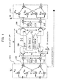
- transmission signals processed by a transmission (transmitter) side matrix calculation processing section 101 based on the unitary matrix V are frequency converted into signals of a radio frequency by a transmission side frequency conversion section 102 including a local oscillator 104, a mixer 103, and a mixer 105 and then transmitted from a fixed antenna section 106 including a plurality of antennas as s 1 and s 2 .
- the notation of the s 1 and s 2 is based on equivalent baseband representation.
- carrier synchronization between antennas is achieved by a local oscillation signal supplied from one local oscillator 104 to the mixers 103 and 105. This results from a restriction on a space-division multiplexing fixed point microwave communication system that deterministic channels are determined based on the phase difference between paths.
- the local oscillators may be provided independently for respective antennas.
- the signals thus transmitted are received by a reception (receiver) side fixed antenna section 107 including a plurality of antennas as r 1 and r 2 .
- the notation of the r 1 and r 2 is based on equivalent baseband representation.
- the reception signals r 1 and r 2 are frequency converted into signals of a baseband frequency by a reception side frequency conversion section 108 including a local oscillator 110, a mixer 109, and a mixer 111 and then processed by a reception side matrix calculation processing section 112 based on the unitary matrix U, whereby signal separation/detection in MIMO is completed.
- carrier synchronization between antennas is achieved by a local oscillation signal supplied from one local oscillator 110 to the mixers 109 and 111. This results from a restriction on a space-division multiplexing fixed point microwave communication system that deterministic channels are determined based on the phase difference between paths.
- the local oscillators may be provided independently for respective antennas as in the case of the transmission end.
- the antennas to be used are not particularly limited and may be a parabola antenna or a horn antenna.
- the matrix calculation processing sections 101 and 112 may be realized by program control or constructed by hardware such as ASIC (Application Specific Integrated Circuit) or the like.
- H 1 e - j ⁇ ⁇ e j ⁇ ⁇ e - j ⁇ 1 ⁇ e j ⁇ ⁇
- the unitary matrix V and unitary matrix U are calculated using the above channel matrix H in the order mentioned.
- the above unitary matrix includes a fluctuation between the channels caused due to external factors such as a fluctuation (modeled by ⁇ in FIG. 1 ) of an antenna position highly sensitive to a subtle change of weather condition such as wind or surrounding temperature.
- a fluctuation modeled by ⁇ in FIG. 1
- the unitary matrix acts so as to compensate for the displacement.
- the local oscillators may be provided independently.
- the feedback information for construction of the V matrix needs to be sent from the reception end to transmission end in this configuration.
- a configuration is adopted in which the displacement is compensated only on the reception side, it is possible to eliminate the need to use the feedback information.
- H 1 e - j ⁇ ⁇ e j ⁇ ⁇ e - j ⁇ 1 ⁇ e j ⁇ ⁇ ⁇ 1 - j ⁇ e j ⁇ ⁇ - j 1 ⁇ e j ⁇ ⁇
- the channel matrix H is effected.
- this is merely an example, and various decomposition methods can be considered based on the same approach, depending on the singular point corresponding to the multiple root.
- first configuration example a configuration example in which the matrix calculation is performed only on the transmission side will be described.
- the channel matrix H is represented by Numeral 68.
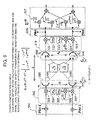
- FIG. 2 A configuration obtained based on the above result is shown in FIG. 2 .
- transmission signals processed by a transmission side matrix calculation processing section 201 based on the unitary matrix V are transmitted from a fixed antenna section 202 including a plurality of antennas as s 1 and s 2 .
- the notation of the s 1 and s 2 is based on equivalent baseband representation, and the frequency conversion processing is omitted here for avoiding complexity.
- the signals thus transmitted are received by a reception side fixed antenna section 203 including a plurality of antennas as r 1 and r 2 .
- the notation of the r 1 and r 2 is based on equivalent baseband representation, and the frequency conversion processing into a signal of a baseband frequency is omitted here for avoiding complexity.
- receiving side matrix calculation processing based on the unitary matrix U is not performed at all, but all matrix calculations are done on the transmission side.
- the matrix in the case where the matrix calculation is performed only on the transmission side, the matrix includes a fluctuation between the channels caused due to external factors such as a fluctuation (modeled by ⁇ in FIG. 2 ) of an antenna position highly sensitive to a subtle change of weather condition such as wind or surrounding temperature.
- a fluctuation modeled by ⁇ in FIG. 2
- the unitary matrix acts so as to compensate for the displacement.
- the thick arrows of FIG. 2 denote virtual orthogonal channels in which channel qualities thereof are proportional to ⁇ 2 and ⁇ 2.
- the antennas to be used are not particularly limited and may be a parabola antenna or a horn antenna.
- the matrix calculation processing section 201 may be realized by program control or constructed by hardware such as ASIC or the like.
- the channel matrix H is represented by Numeral 70.
- matrix V H is represented by Numeral 71.
- V H e j ⁇ ⁇ 2 + e - j ⁇ ⁇ 2 0 0 - j ⁇ e j ⁇ ⁇ 2 - e - j ⁇ ⁇ 2 - 1 ⁇ 1 e - j ⁇ ⁇ e j ⁇ ⁇ e - j ⁇ 1 ⁇ e j ⁇ ⁇
- the V H is no longer a unitary matrix. Therefore, in order to calculate the matrix V, inverse matrix calculation is required.
- the channel matrix H is effected.
- a given matrix A represented by Numeral 76 is assumed.
- A a 11 a 12 a 21 a 22
- the inverse matrix A -1 of the above matrix A is represented by Numeral 77.
- transmission signals processed by a transmission side matrix calculation processing section 301 based on the unitary matrix V are transmitted from a fixed antenna section 302 including a plurality of antennas as s 1 and s 2 .
- the notation of the s 1 and s 2 is based on equivalent baseband representation, and the frequency conversion processing is omitted here for avoiding complexity.
- the signals thus transmitted are received by a reception side fixed antenna section 303 including a plurality of antennas as r 1 and r 2 .
- the notation of the r 1 and r 2 is based on equivalent baseband representation, and the frequency conversion processing into a signal of a baseband frequency is omitted here for avoiding complexity.
- receiving side matrix calculation processing based on the unitary matrix U is not performed at all, but all matrix calculations are done on the transmission side.
- the matrix includes a fluctuation between the channels caused due to external factors such as a fluctuation (modeled by ⁇ in FIG. 3 ) of an antenna position highly sensitive to a subtle change of weather condition such as wind or surrounding temperature.
- a fluctuation modeled by ⁇ in FIG. 3
- the transmission side matrix acts so as to compensate for the displacement.
- the antennas to be used are not particularly limited and may be a parabola antenna or a horn antenna.
- the matrix calculation processing section 301 may be realized by program control or constructed by hardware such as ASIC or the like.
- FIG. 20 An application of the configuration in which the matrix calculation is performed only on the transmission side is shown in FIG. 20 .
- a plurality of antennas are provided in a transmission station 2001 located near a backbone network, and one antenna is provided in reception stations 2002 and 2003, located near a user network, respectively.
- the reception station 2001 and reception station 2003 are located far away from each other and, therefore, matrix calculation cannot be performed.
- the transmission station 2001 can perform the matrix calculation.
- Such a concept in "one station to many stations" configuration may be applied to "many stations to one station” configuration to be described later as a configuration in which the matrix calculation is performed only on the reception side.
- This third configuration has the following features: the feedback information to be sent from the reception end to transmission end is not required; local oscillators may be provided independently for respective antennas on the transmission side; and exactly the same characteristics as those of the SVD method can be shown.
- Numeral 80 can be obtained as the channel matrix H.
- U H 1 / 2 j / 2 j ⁇ e - j ⁇ ⁇ / 2 e j ⁇ ⁇ / 2
- U H 1 / 2 j / 2 j ⁇ e - j ⁇ ⁇ / 2 e - j ⁇ ⁇ / 2
- ⁇ 2 ⁇ ⁇ d
- FIG. 4 A configuration obtained based on the above result is shown in FIG. 4 .
- transmission side matrix calculation processing based on the unitary matrix V is not performed at all, but all matrix calculations are done on the reception side.
- the matrix includes a fluctuation between the channels caused due to external factors such as a fluctuation (modeled by ⁇ in FIG. 4 ) of an antenna position highly sensitive to a subtle change of weather condition such as wind or surrounding temperature.
- a fluctuation modeled by ⁇ in FIG. 4
- the unitary matrix acts so as to compensate for the displacement.
- antenna separation length must be widened in view of a frequency to be used in the fixed point microwave communication system.
- local oscillators are installed near the antennas. That is, the point that the local oscillators are provided independently for respective antennas on the transmission side is the biggest feature of the third configuration.
- transmission signal are added with pilot signals of respective antennas by a pilot signal generation section 401, frequency converted into signals of a radio frequency by a transmission side frequency conversion section 402 including local oscillators 404 and 405, mixers 403 and 407, and then transmitted from a fixed antenna section 408 including a plurality of antennas as s 1 and s 2 .
- the notation of the s 1 and s 2 is based on equivalent baseband representation.
- Reference numeral 406 is the modeling of the phase noise ⁇ L .
- the signals thus transmitted are received by a reception side fixed antenna section 409 including a plurality of antennas as r 1 and r 2 .
- the notation of the r 1 and r 2 is based on equivalent baseband representation, and the frequency conversion processing into a signal of a baseband frequency is omitted here for avoiding complexity.
- the reception signals r 1 and r 2 are processed by a reception side matrix calculation processing section 410 based on the unitary matrix U, whereby signal separation/detection in MIMO is completed.
- transmission side matrix calculation processing based on the unitary matrix V is not performed at all, but all matrix calculations are done on the reception side.
- the matrix in the case where the matrix calculation is performed only on the reception side, the matrix includes a fluctuation between the channels caused due to external factors such as a fluctuation (modeled by ⁇ A in FIG. 4 ) of an antenna position highly sensitive to a subtle change of weather condition such as wind or surrounding temperature. Further, the matrix includes the phase noise ⁇ L due to absence of synchronization between carriers. Thus, even when the displacement in the highly sensitive antenna direction or phase variation between carriers occurs, the unitary matrix acts so as to compensate for the displacement or phase variation.
- the greatest merit of the third example is that it is not necessary to send the feedback information for construction of the V matrix from the reception end to transmission end.
- the thick arrows of FIG. 4 denote virtual orthogonal channels in which channel qualities thereof are proportional to ⁇ 2 and ⁇ 2.
- the antennas to be used are not particularly limited and may be a parabola antenna or a horn antenna.
- the matrix calculation processing section 401 may be realized by program control or constructed by hardware such as ASIC or the like.
- fourth example a configuration example in which virtual orthogonal channels having the same width are formed, the unitary matrix calculation is performed only on the reception side, and local oscillators are provided independently for respective antennas on both the transmission and reception sides will be described.
- This fourth configuration has the following features: the feedback information to be sent from the reception end to transmission end is not required; local oscillators may be provided independently for respective antennas on both the transmission and reception sides; and exactly the same characteristics as those of the SVD method can be shown. Further, analysis is made based on a fact that a significant phase rotation due to movement in the antenna direction highly sensitive to a subtle change of weather condition such as wind or surrounding temperature can be traced to the same modeling as a phase rotation in the local oscillators provided for respective antennas both on the transmission and reception sides. Note that the above theoretical analysis analytically reveals that the above increase in channel capacity can be achieved even when such a displacement in the highly sensitive antenna direction occurs.
- Numeral 82 can be obtained as the channel matrix H.
- U H 1 / 2 1 ⁇
- FIG. 5 A configuration obtained based on the above result is shown in FIG. 5 .
- transmission side matrix calculation processing based on the unitary matrix V is not performed at all, but all matrix calculations are done on the reception side.
- the matrix includes a fluctuation between the channels caused due to external factors such as a fluctuation (modeled by ⁇ A and ⁇ A in FIG. 5 ) of a transmission antenna position and reception antenna position highly sensitive to a subtle change of weather condition such as wind or surrounding temperature.
- the unitary matrix acts so as to compensate for the displacement.
- antenna separation length must be widened in view of a frequency to be used in the fixed point microwave communication system.
- local oscillators are installed near the antennas. That is, the point that the local oscillators are provided independently for respective antennas on both the transmission and reception sides is the biggest feature of the fourth configuration. Thus, even if the local oscillators are used independently for respective antennas on both the transmission and reception sides, it is possible to obtain characteristics equivalent to the SVD method by appropriately detecting the pilot signals.
- transmission signal are added with pilot signals of respective antennas by a pilot signal generation section 501, frequency converted into signals of a radio frequency by a transmission side frequency conversion section 502 including local oscillators 504 and 505, mixers 503 and 507, and then transmitted from a fixed antenna section 508 including a plurality of antennas as s 1 and s 2 .
- the notation of the s 1 and s 2 is based on equivalent baseband representation.
- the local oscillators 504 and 505 are used independently for respective antennas. Thus, carrier synchronization is not achieved between carriers from the respective antennas, resulting in generation of phase noise ⁇ L .
- Reference numeral 506 is the modeling of the phase noise ⁇ L .
- the signals thus transmitted are received by a reception side fixed antenna section 509 including a plurality of antennas as r 1 and r 2 .
- the notation of the r 1 and r 2 is based on equivalent baseband representation.
- the reception signals r 1 and r 2 are frequency converted into signals of a baseband frequency by a reception side frequency conversion section 510 including local oscillators 512 and 513, mixers 511 and 515, passed through a pilot signal detection section 516, and processed by a reception side matrix calculation processing section 517 based on the unitary matrix U, whereby signal separation/detection in MIMO is completed.
- the local oscillators 512 and 513 are used independently for respective antennas on the reception side.
- phase noise ⁇ L is generated due to absence of synchronization between carriers.
- Reference numeral 514 is the modeling of the phase noise ⁇ L .
- the antennas to be used are not particularly limited and may be a parabola antenna or a horn antenna.
- the matrix calculation processing section 517 may be realized by program control or constructed by hardware such as ASIC or the like.
- all matrix calculations can be done only on the reception side with the transmission side matrix calculation processing based on the unitary matrix V omitted. This is because that, as can be seen from Numeral 82, the unitary matrix acts so as to compensate for a fluctuation between the channels caused due to external factors such as a fluctuation (modeled by ⁇ A and ⁇ A in FIG.
- the thick arrows of FIG. 5 denote virtual orthogonal channels in which channel qualities thereof are proportional to ⁇ 2 and ⁇ 2.
- the orthogonal channels thus formed are not influenced by the phase difference ⁇ or ⁇ . Feedback from the reception end to the transmission end is not necessary. Further, since the matrix used is the unitary matrix, exactly the same characteristics as those of the SVD method can be shown.
- a fifth example (fifth configuration example) of the present invention a configuration example in which virtual orthogonal channels having different widths are formed, the matrix calculation is performed only on the reception side, and local oscillators are provided independently for respective antennas on both the transmission and reception sides will be described.
- This fifth configuration has the following features : virtual orthogonal channels have different values; feedback information to be sent from the reception side to transmission side is not required; and local oscillators may be provided independently for respective antennas on both the transmission and reception sides. Further, analysis is made based on a fact that a significant phase rotation due to movement in the antenna direction highly sensitive to a subtle change of weather condition such as wind or surrounding temperature can be traced to the same modeling as a phase rotation in the local oscillators provided for respective antennas both on the transmission and reception sides. Further, for flexibility, antenna separation length is set based on antenna positions different from optimum antenna positions. Therefore, different characteristics from the SVD method are shown. The characteristic analysis of this configuration will be described later.
- the channel matrix H is represented by Numeral 84.
- H 1 e - j ⁇ ⁇ e j ⁇ ⁇ e - j ⁇ ⁇ e j ⁇ ⁇ 1 ⁇ e j ⁇ ⁇ + ⁇ ⁇
- transmission side highly sensitive antenna displacement ⁇ A is included in phase variation ⁇ L in the transmission side local oscillators provided independently for respective antennas to obtain ⁇
- reception side highly sensitive antenna displacement ⁇ A is included in phase variation ⁇ L in the reception side local oscillators provided independently for respective antennas to obtain ⁇ .
- U 1 e - j ⁇ ⁇ e j ⁇ ⁇ e - j ⁇ ⁇ e j ⁇ 1 ⁇ e j ⁇ ⁇ + ⁇ ⁇ e j ⁇ ⁇ 2 + e - j ⁇ ⁇ 2 0 0 - j ⁇ e j ⁇ ⁇ 2 - 1
- the channel matrix H is effected.
- inverse matrix U -1 of U is considered.
- a given matrix A represented by Numeral 91 is assumed.
- A a 11 a 12 a 21 a 22
- the inverse matrix A -1 of the above matrix A is represented by Numeral 92.
- transmission signals are added with pilot signals of respective antennas by a pilot signal generation section 601.
- the orthogonal pilot signals used may be an orthogonal pattern obtained from the Hadamard matrix or may be a CAZAC sequence.
- the transmission signals thus added with the pilot signals are frequency converted into signals of a radio frequency by a transmission side frequency conversion section 602 including transmission side local oscillators 604 and 605, mixers 603 and 607, and then transmitted from a fixed antenna section 608 including a plurality of antennas as s 1 and s 2 .
- the notation of the s 1 and s 2 is based on equivalent baseband representation.
- the local oscillators 604 and 605 are used independently for respective antennas. Thus, carrier synchronization is not achieved between carriers from the respective antennas, resulting in generation of phase noise ⁇ L .
- Reference numeral 606 is the modeling of the phase noise ⁇ L .
- the signals thus transmitted are received by a reception side fixed antenna section 609 including a plurality of antennas as r 1 and r 2 .
- the notation of the r 1 and r 2 is based on equivalent baseband representation.
- the reception signals r 1 and r 2 are frequency converted into signals of a baseband frequency by a reception side frequency conversion section 610 including local oscillators 612 and 613, mixers 611 and 615, passed through a pilot signal detection section 616, and processed by a reception side matrix calculation processing section 617 based on the unitary matrix U, whereby signal separation/detection in MIMO is completed.
- phase noise ⁇ L is generated due to absence of carrier synchronization between antennas.
- Reference numeral 614 is the modeling of the phase noise ⁇ L .
- the antennas to be used are not particularly limited and may be a parabola antenna or a horn antenna.
- the matrix calculation processing section 617 may be realized by program control or constructed by hardware such as ASIC or the like.
- the orthogonal pilot signals used is an orthogonal pattern such as the Hadamard sequence or CAZAC sequence, so that the ⁇ and ⁇ can be detected using a simple correlator (not shown). All matrix calculations can be done only on the reception side. That is, as can be seen from Numeral 93, the reception side matrix acts so as to compensate for a fluctuation between the channels caused due to external factors such as a fluctuation (modeled by ⁇ A and ⁇ A in FIG. 6 ) of an antenna position highly sensitive to a subtle change of weather condition such as wind or surrounding temperature and phase noise ⁇ L or ⁇ L caused due to absence of synchronization between carriers.
- the greatest merit of the fifth example is that it is not necessary to send the feedback information for construction of the V matrix from the reception end to transmission end.
- the thick arrows of FIG. 6 denote virtual orthogonal channels having different widths, unlike the fourth example. However, as described later, the virtual orthogonal channels in this configuration have the same channel quality.
- the present invention is not limited to this, but a configuration using three or more antennas is possible.
- singular value orthogonal matrix ⁇ 1/2 is represented by Numeral 94.
- Numeral 95 is derived, and channel matrix H can be represented by Numeral 96.
- n ⁇ d 2 R n 2 ⁇ ⁇ 3
- Numeral 97 can be obtained.
- ⁇ U H 1 3 e j ⁇ ⁇ 3 ⁇ e - j ⁇ ⁇ 1 3 e j ⁇ 4 ⁇ ⁇ 3 ⁇ e - j ⁇ ⁇ 2 3 e j ⁇ ⁇ 3 ⁇ e - j ⁇ ⁇ 1 3 1 ⁇ e - j ⁇ ⁇ 1 + ⁇ 1 3 e j ⁇ ⁇ 3 ⁇ e - j ⁇ ⁇ 2 + ⁇ 1 3 e j ⁇ 4 ⁇ ⁇ 3 ⁇ e - j ⁇ ⁇ 2 3 e j ⁇ ⁇ 3 ⁇ e - j ⁇ ⁇ 1 + ⁇ 2 3 1 ⁇ e - j ⁇ ⁇ 2 + ⁇ 2 3 1 ⁇ e - j ⁇ ⁇ 2 + ⁇ 2 3 ⁇ e - j ⁇ ⁇ 2 + ⁇ 2 3 ⁇ e - j ⁇
- ⁇ A and ⁇ A in Numeral 97 each represent a carrier phase rotation caused due to a fluctuation of the transmission/reception side antennas highly sensitive to a subtle change of weather condition such as wind or surrounding temperature.
- Suffixes 1 and 2 represent a positional displacement of second and third antennas counting from the uppermost antennas.
- antenna separation length must be widened in view of a frequency to be used in the fixed point microwave communication system.
- local oscillators are installed near the antennas. That is, the local oscillators are provided independently for respective antennas on both the transmission and reception sides. Accordingly, phase noise ⁇ L or ⁇ L is caused due to absence of synchronization between carriers.
- Suffixes 1 and 2 represent a positional displacement of second and third antennas counting from the uppermost antennas.
- the channel capacity becomes three times higher than the total power delivered to all antennas.
- singular value orthogonal matrix ⁇ 1/2 is represented by Numeral 98.
- Numeral 99 is derived, and channel matrix H can be represented by Numeral 100.
- n ⁇ d 2 R n 2 ⁇ ⁇ 4
- Numeral 101 each represent a carrier phase rotation caused due to a fluctuation of the transmission/reception side antennas highly sensitive to a subtle change of weather condition such as wind or surrounding temperature.
- Suffixes 1, 2, and 3 represent a positional displacement of second, third, and fourth antennas counting from the uppermost antennas.
- Antenna separation length must be widened in view of a frequency to be used in the fixed point microwave communication system.
- local oscillators are installed near the antennas. That is, the local oscillators are provided independently for respective antennas on both the transmission and reception sides. Accordingly, phase noise ⁇ L or ⁇ L is caused due to absence of synchronization between carriers.
- Suffixes 1, 2, and 3 represent a positional displacement of second, third, and fourth antennas counting from the uppermost antennas.
- the virtual orthogonal channels can be formed by the unitary matrix calculation only on the reception side.
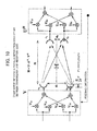
- the thick arrows of FIG. 8 denote virtual orthogonal channels in which channel qualities thereof are proportional to ⁇ 4 , ⁇ 4 , ⁇ 4 , and ⁇ 4.
- the channel capacity becomes four times higher than the total power delivered to all antennas.
- a configuration using an arbitrary number N of antennas is considered.
- singular value orthogonal matrix ⁇ 1/2 is represented by Numeral 102.
- a transmission side phase rotation matrix T is defined by Numeral 105.
- T 1 0 ⁇ 0 0 e j ⁇ ⁇ 1 ⁇ 0 ⁇ ⁇ ⁇ ⁇ 0 0 ⁇ e j ⁇ ⁇ N - 1
- a reception side phase rotation matrix W is defined by Numeral 106.
- W 1 0 ⁇ 0 0 e j ⁇ ⁇ 1 ⁇ 0 ⁇ ⁇ ⁇ ⁇ 0 0 ⁇ e j ⁇ ⁇ N - 1
- Numeral 101 each represent a carrier phase rotation caused due to a fluctuation of the transmission/reception side antennas highly sensitive to a subtle change of weather condition such as wind or surrounding temperature.
- ⁇ L or ⁇ L represents a phase variation caused due to absence of synchronization between carriers.
- Each suffix represents the order of antennas counting from the uppermost antennas.
- H o H ⁇ H o 1 e j ⁇ ⁇ N ⁇ e j ⁇ N - 1 2 ⁇ ⁇ N e j ⁇ ⁇ N 1 ⁇ e j ⁇ N - 2 2 ⁇ ⁇ N ⁇ ⁇ ⁇ ⁇ e j ⁇ N - 1 2 ⁇ ⁇ N e j ⁇ N - 2 2 ⁇ ⁇ N ⁇ 1 ⁇ 1 e - j ⁇ ⁇ N ⁇ e - j ⁇ N - 1 2 ⁇ ⁇ N e - j ⁇ ⁇ N 1 ⁇ e - j ⁇ N 1 ⁇ e - j ⁇ N - 2 2 ⁇ ⁇ N ⁇ ⁇ ⁇ ⁇ e j ⁇ N - 1 2 ⁇ ⁇ N e - j ⁇ N - 2 2 ⁇ ⁇ N ⁇ ⁇ ⁇ ⁇ e j ⁇ N - 1 2 ⁇ ⁇ N e
- an arbitrary column vector or arbitrary row vector is a vector obtained by cyclic-shifting Chu sequence, and the autocorrelation values thereof (E[a ⁇ a*]) are orthogonal to each other.
- N is an odd number, cyclic shift does not appear.
- singular value orthogonal matrix ⁇ 1/2 is represented by Numeral 118.
- the virtual orthogonal channels can be formed by the matrix calculation only on the reception side even in the case where the local oscillators are provided independently for respective antennas and where a displacement in the highly sensitive antenna direction occurs.
- a fixed transmission matrix V may be any one as long as it is a unitary matrix, and a reception side unitary matrix calculation is represented by Numeral 123 to act so as to compensate for a fluctuation caused by the local oscillators or due to antenna displacement.
- U H V H N ⁇ T H ⁇ H o H ⁇ W H
- H o 1 - j - j 1
- H o H ⁇ H o 1 e j ⁇ ⁇ N ⁇ e j ⁇ N - 1 2 ⁇ ⁇ N e j ⁇ ⁇ N 1 ⁇ e j ⁇ N - 2 2 ⁇ ⁇ N ⁇ ⁇ ⁇ ⁇ e j ⁇ N - 1 2 ⁇ ⁇ N e j ⁇ N - 2 2 ⁇ ⁇ N ⁇ 1 ⁇ 1 e - j ⁇ ⁇ N ⁇ e - j ⁇ N - 1 2 ⁇ ⁇ N e - j ⁇ ⁇ N 1 ⁇ e - j ⁇ ⁇ N 1 ⁇ e - j ⁇ N 1 ⁇ e - j ⁇ N - 2 2 ⁇ ⁇ N ⁇ ⁇ ⁇ ⁇ e j ⁇ N - 1 2 ⁇ ⁇ N e - j ⁇ N - 2 2 ⁇ ⁇ N ⁇ ⁇ ⁇ ⁇ e j
- H o H ⁇ H o 1 e j ⁇ ⁇ N ⁇ e j ⁇ N - 1 2 ⁇ ⁇ N e j ⁇ ⁇ N 1 ⁇ e j ⁇ N - 2 2 ⁇ ⁇ N ⁇ ⁇ ⁇ ⁇ e j ⁇ N - 1 2 ⁇ ⁇ N e j ⁇ N - 2 2 ⁇ ⁇ N ⁇ 1 ⁇ 1 e - j ⁇ ⁇ N ⁇ e - j ⁇ N - 1 2 ⁇ ⁇ N e - j ⁇ ⁇ N 1 ⁇ e - j ⁇ N 1 ⁇ e - j ⁇ N - 2 2 ⁇ ⁇ N ⁇ ⁇ ⁇ ⁇ e j ⁇ N - 1 2 ⁇ ⁇ N e - j ⁇ N - 2 2 ⁇ ⁇ N ⁇ ⁇ ⁇ ⁇ e j ⁇ N - 1 2 ⁇ ⁇ N e
- the fifth configuration example is used as an example.
- Characteristics analysis is performed for the fifth configuration example in which antenna separation length is set based on antenna positions different from optimum antenna positions for flexibility, while comparing to the SVD method.
- reception signal vector is r
- a signal vector after the matrix calculation on the reception side is represented by Numeral 134.
- S denotes a transmission signal vector
- n denotes a noise vector.
- a reception signal vector after unitary matrix calculation according to the SVD method is represented by Numeral 140.
- the SNR 2 of ⁇ 2 channel is represented by Numeral 143.
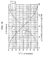
- the proposed method exhibits the same SNR value between the orthogonal channels ⁇ 1 and ⁇ 2 and thus it can be understood that a fluctuation with respect to the antenna separation length is small.
- Signal power after the matrix calculation on the reception side is proportional to eigenvalue both in the proposed method and SVD method.
- the matrix calculation on the reception side is based on the unitary matrix, so that noise power does not change but keeps a constant value even if the eigenvalue changes. Therefore, the SNRs of the respective paths in the SNR method become different values which are proportional to the eigenvalue and change in accordance with the antenna separation length.
- the matrix calculation on the reception side is not based on the unitary matrix, so that noise power changes in accordance with eigenvalue.
- the SNR with respect to the virtual orthogonal channel does not change even when the antenna separation length changes and, if a change occurs, the change amount is small, so that it can be said that the proposed method is more practical and easier to use than the SVD method.
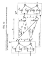
- FIG. 11 which is obtained by modeling the lower half of the vertically symmetric configuration of FIG. 10 is used to perform analysis as follows.
- R is set as a reference.
- phase rotation ⁇ obtained based on the channel difference between two waves at the reception points is represented by Numeral 146.
- the channel matrix H normalized by the diagonal channel of angle ⁇ 1 is represented by Numeral 148.
- H 1 e - j ⁇ ⁇ e j ⁇ ⁇ e - j ⁇ 1 ⁇ e j ⁇ ⁇
- R is set as a reference, as in the above case.
- d 11 the channel difference of a diagonal channel with respect to R is represented by Numeral 152.
- the channel matrix H is represented by Numeral 163.
- U 1 / 2 j ⁇ e - j ⁇ / 2 j ⁇ e - j ⁇ / 2 1 / 2
- U 1 / 2 j ⁇ e - j ⁇ / 2 j ⁇ e
- the channel matrix H focusing only on a phase difference between reception antennas is represented by Numeral 166.
- H 1 e j - 2 ⁇ ⁇ ⁇ ⁇ d 12 - d 11 e j - 2 ⁇ ⁇ ⁇ ⁇ d 21 - d 22 1
- the pilot signals are used as a detectionmeans for detecting a fluctuation of an antenna position or a fluctuation of channels caused by an external factors or a phase variation caused due to use of the local oscillators provided independently for respective antennas.
- the above fluctuations can be detected by a configuration not using the pilot signals.
- a method that uses data for conveying information may be employed.
- a method that estimates a phase variation using a determination result after equalization or method that estimates a phase variation by re-encoding a signal after error correction may be employed.
- the method that detects the above fluctuations without use of the pilot signals will be described taking a case where two antennas are used as an example.
- channel matrix represented by Numeral 176.
- H 1 - j ⁇ e j ⁇ ⁇ - j ⁇ e j ⁇ 1 ⁇ e j ⁇ ⁇ + ⁇
- transmission and reception signal vectors are represented by Numeral 177.
- S s 1 s 2
- Y y 1 y 2
- Numeral 178 can be obtained.
- Numeral 180 is obtained from Numeral 179.
- y 1 s 1 - j ⁇ e j ⁇ ⁇ s 2
- e j ⁇ ⁇ s 1 - y 1 j ⁇ s 2 From this, ⁇ can be detected.
- FIG. 16 is an example in which optical channels are used as deterministic channels.
- a laser diode (LD) 1601 and a photodetector (PD) 1602 are used on the transmission side and reception side, respectively.
- the line-of-sight MIMO can be realized as in the case of the line-of-sight MIMO using electrical waves.
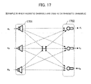
- FIG. 17 is an example in which acousto-optic channels are used as deterministic channels.
- an ultrasonic oscillator 1701 and an ultrasonic microphone 1702 are used on the transmission side and reception side, respectively.
- the line-of-sight MIMO can be realized as in the case of the line-of-sight MIMO using electrical waves.
- FIG. 18 is an example of a MIMO antenna used in line-of-sight channels such as a simple radio apparatus (including a wireless LAN) used as deterministic channels.
- a simple radio apparatus including a wireless LAN
- the simple radio apparatus has line-of-sight channels having a complicated structure. It is possible to increase communication capacity in the line-of-sight MIMO as long as the condition of Numeral 175 is satisfied regardless of the type of a geometric form of the line-of-sight channels.
- the MIMO antenna of FIG. 18 has a configuration in which antenna separation length (d) between antenna elements 1801 and 1802 can be freely varied by a connection bar 1803. Further, angle ( ⁇ ) formed between the antenna elements 1801 and 1802 can be freely controlled by a hinge 1804.
- the derived Numeral 175 represents that it is possible to achieve the maximum communication capacity by controlling the antenna separation lengths d T , d R and angles ⁇ T , ⁇ R . It follows that, by controlling the antenna separation length (d) and angle ( ⁇ ) in the MIMO antenna, it is possible to achieve the maximum communication capacity regardless of the type of a geometric form of the line-of-sight channels.
- the MIMO communication system includes a plurality of channels. Further, the system includes a channel matrix calculation processing section on a transmission or reception side or both of the transmission and reception sides.
- the channel matrix calculation processing section updates an orthogonal channel formation matrix in accordance with a fluctuation of a transmission antenna position (e.g., a transmission antenna, light-emitting device, speaker, and the like used in electric wave propagation) or reception antenna (e.g., a reception antenna, light-receiving device, microphone, and the like used in electric wave propagation) or a fluctuation of the channels.
- a transmission antenna position e.g., a transmission antenna, light-emitting device, speaker, and the like used in electric wave propagation
- reception antenna e.g., a reception antenna, light-receiving device, microphone, and the like used in electric wave propagation
- a configuration may be adopted in which geometric parameters of the channels are set so that the eigenvalue of the channel matrix becomes multiplicity condition, and calculation of a unitary matrix constituted based on an eigenvector obtained from the eigenvalue or an eigenvector obtained from the linear sum of eigenvector is performed on one of the transmission side or reception side.
- the MIMO communication system may be a fixed point microwave communication system using a plurality of antennas and constituted by using local oscillators provided independently for respective antennas on one or both of the transmission and reception sides.
- the MIMO communication system may include a means for detecting a fluctuation of a transmission antenna position or reception antenna position or a fluctuation of the channels and use a detection result from the means to update a virtual orthogonal channel formation matrix.
- matrix calculation processing for formation of the virtual orthogonal channels may be performed only on the reception side.
- the MIMO communication system may include a means for transmitting pilot signals from the transmission side to reception side.
- a fluctuation of a transmission antenna position or reception antenna position or a fluctuation of the channels is detected by the pilot signals and a virtual orthogonal channel formation matrix is updated based on a result of the detection.
- the MIMO communication system may include a means for transmitting pilot signals of respective antennas from the transmission side to reception side and, based on the pilot signals, perform matrix calculation processing for formation of the virtual orthogonal channels only on the reception side.
- pilot signals to be transmitted from the transmission side to reception side may be generated before processing performed by the local oscillators.
- phase noise between local oscillators generated on the transmission side can be detected on the reception end, and the generated phase noise can be compensated for by updating the matrix.
- the detection of the pilot signals that have been transmitted from the transmission side to reception side may be performed after processing performed by the local oscillators on the reception side.
- phase noise between local oscillators generated on the reception side can be detected on the reception end, and the generated phase noise can be compensated for by updating the matrix.
- pilot signals transmitted from the transmission side to reception side may be orthogonal between transmission antennas.
- phase noise between the local oscillators and a displacement in the highly sensitive antenna direction caused due to weather condition can be detected by a simple correlator, and the detected phase noise or displacement can be compensated for by updating the matrix.
- the line-of-sight channels may be used as optical channels or acoustic channels, as well as electrical wave channels. Also in this case, the MIMO communication system can be provided.
- one or both of the antenna separation length between a plurality of transmission antennas or a plurality of reception antennas and direction of a plurality of transmission antennas or a plurality of reception antennas may be made changeable. With this configuration, it is possible to provide a MIMO communication system where the maximum communication capacity can always be achieved by controlling one or both of the antenna separation length between the transmission antennas or reception antennas and axial direction of the transmission antennas or reception antennas, regardless of the type of a geometric form of the line-of-sight channels.
- the abovementioned effects need not be achieved simultaneously but at least one of the effects may be achieved.
Landscapes
- Engineering & Computer Science (AREA)
- Computer Networks & Wireless Communication (AREA)
- Signal Processing (AREA)
- Physics & Mathematics (AREA)
- Mathematical Physics (AREA)
- Power Engineering (AREA)
- Radio Transmission System (AREA)
- Mobile Radio Communication Systems (AREA)
Applications Claiming Priority (2)
| Application Number | Priority Date | Filing Date | Title |
|---|---|---|---|
| JP2006312277 | 2006-11-17 | ||
| PCT/JP2007/072411 WO2008059985A1 (fr) | 2006-11-17 | 2007-11-19 | Système de communication mimo à trajets de communication déterministes, et procédé |
Publications (3)
| Publication Number | Publication Date |
|---|---|
| EP2091168A1 true EP2091168A1 (fr) | 2009-08-19 |
| EP2091168A4 EP2091168A4 (fr) | 2016-03-30 |
| EP2091168B1 EP2091168B1 (fr) | 2018-12-26 |
Family
ID=39401787
Family Applications (1)
| Application Number | Title | Priority Date | Filing Date |
|---|---|---|---|
| EP07832141.1A Not-in-force EP2091168B1 (fr) | 2006-11-17 | 2007-11-19 | Système de communication mimo à trajets de communication déterministes, et procédé |
Country Status (8)
| Country | Link |
|---|---|
| US (1) | US20090296846A1 (fr) |
| EP (1) | EP2091168B1 (fr) |
| JP (1) | JP5429602B2 (fr) |
| CN (2) | CN101542936B (fr) |
| AU (1) | AU2007320337B2 (fr) |
| BR (1) | BRPI0717203A2 (fr) |
| RU (1) | RU2462816C2 (fr) |
| WO (1) | WO2008059985A1 (fr) |
Cited By (1)
| Publication number | Priority date | Publication date | Assignee | Title |
|---|---|---|---|---|
| EP2180623A4 (fr) * | 2007-08-02 | 2016-08-10 | Nec Corp | Système de communication mimo ayant un parcours de communication déterministe et son procédé d'agencement d'antenne |
Families Citing this family (34)
| Publication number | Priority date | Publication date | Assignee | Title |
|---|---|---|---|---|
| KR20090018028A (ko) * | 2006-04-04 | 2009-02-19 | 파나소닉 주식회사 | 광 공간 전송 시스템에 사용되는 수신 장치 |
| EP2219310A4 (fr) | 2007-11-30 | 2014-02-19 | Nec Corp | Système de communication sans fil, récepteur, émetteur, procédé de communication sans fil, procédé de réception et procédé d'émission |
| JP5512458B2 (ja) * | 2010-06-17 | 2014-06-04 | パナソニック株式会社 | プリコーディング方法、プリコーディング装置、送信方法、送信装置、受信方法および受信装置 |
| WO2012167823A1 (fr) * | 2011-06-08 | 2012-12-13 | Telefonaktiebolaget L M Ericsson (Publ) | Récupération de porteuses communes pour des systèmes mimo |
| US9780928B2 (en) | 2011-10-17 | 2017-10-03 | Golba Llc | Method and system for providing diversity in a network that utilizes distributed transceivers and array processing |
| EP2847866A4 (fr) * | 2012-03-30 | 2015-12-16 | Rensselaer Polytech Inst | Système de communication à travers un mur multicanal utilisant une suppression de diaphonie |
| US8873662B2 (en) * | 2012-04-05 | 2014-10-28 | Ericsson Modems Sa | MIMO configuration methods and apparatus |
| US9077407B2 (en) * | 2012-05-15 | 2015-07-07 | Broadcom Corporation | Geometrical closed loop line of sight (LOS) multiple-input-multiple-output (MIMO) |
| US9197982B2 (en) * | 2012-08-08 | 2015-11-24 | Golba Llc | Method and system for distributed transceivers for distributed access points connectivity |
| JP6083292B2 (ja) * | 2013-03-28 | 2017-02-22 | 富士通株式会社 | 近距離mimoのアンテナ配置方法、プログラムおよび伝送システム |
| JP6171580B2 (ja) | 2013-05-31 | 2017-08-02 | 富士通株式会社 | 通信システム、通信装置及びアンテナ要素配置方法 |
| WO2014199451A1 (fr) | 2013-06-11 | 2014-12-18 | 富士通株式会社 | Dispositif d'antenne et système d'émission de signal |
| WO2014202156A1 (fr) * | 2013-06-18 | 2014-12-24 | Telefonaktiebolaget L M Ericsson (Publ) | Annulation de fuite pour émetteur-récepteur entrée multiple sortie multiple |
| ITMI20131108A1 (it) * | 2013-07-02 | 2015-01-03 | Siae Microelettronica Spa | Metodo, apparecchiatura e sistema di ricostruzione di terne di segnali trasmessi su ponti radio mimo a tre antenne per polarizzazione di trasmissione |
| CN104717024B (zh) * | 2013-12-12 | 2017-06-13 | 华为技术有限公司 | 一种天线对mimo系统性能影响的评估方法及装置 |
| WO2015110180A1 (fr) * | 2014-01-27 | 2015-07-30 | Telefonaktiebolaget L M Ericsson (Publ) | Système pour l'évaluation d'un déploiement d'antenne à entrées multiples sorties multiples (mimo) |
| JP6583292B2 (ja) | 2015-01-05 | 2019-10-02 | 日本電気株式会社 | Mimo復調装置及び方法、並びに見通し内mimo無線通信システム |
| WO2016148262A1 (fr) * | 2015-03-17 | 2016-09-22 | 日本電気株式会社 | Dispositif, procédé et système de communication, terminal et programme |
| KR102410157B1 (ko) * | 2016-03-17 | 2022-06-17 | 한국전자통신연구원 | Los 환경에서 mimo 사용하여 전송량 증대가 가능한 무선 통신 장치 및 그 방법 |
| US10854995B2 (en) | 2016-09-02 | 2020-12-01 | Movandi Corporation | Wireless transceiver having receive antennas and transmit antennas with orthogonal polarizations in a phased array antenna panel |
| US10199717B2 (en) | 2016-11-18 | 2019-02-05 | Movandi Corporation | Phased array antenna panel having reduced passive loss of received signals |
| US10321332B2 (en) | 2017-05-30 | 2019-06-11 | Movandi Corporation | Non-line-of-sight (NLOS) coverage for millimeter wave communication |
| US10916861B2 (en) | 2017-05-30 | 2021-02-09 | Movandi Corporation | Three-dimensional antenna array module |
| US10484078B2 (en) | 2017-07-11 | 2019-11-19 | Movandi Corporation | Reconfigurable and modular active repeater device |
| US10411772B1 (en) * | 2017-07-26 | 2019-09-10 | The United States Of America As Represented By The Secretary Of The Air Force | Robust spectrally efficient line-of-sight (LOS) wireless communications with geometrically-distributed antenna arrays |
| JP7017367B2 (ja) * | 2017-10-26 | 2022-02-08 | 池上通信機株式会社 | パラメトリック方式を用いた水中音響mimo通信システム |
| US10862559B2 (en) | 2017-12-08 | 2020-12-08 | Movandi Corporation | Signal cancellation in radio frequency (RF) device network |
| US10090887B1 (en) | 2017-12-08 | 2018-10-02 | Movandi Corporation | Controlled power transmission in radio frequency (RF) device network |
| US10637159B2 (en) | 2018-02-26 | 2020-04-28 | Movandi Corporation | Waveguide antenna element-based beam forming phased array antenna system for millimeter wave communication |
| US11088457B2 (en) | 2018-02-26 | 2021-08-10 | Silicon Valley Bank | Waveguide antenna element based beam forming phased array antenna system for millimeter wave communication |
| CN110873825B (zh) * | 2018-09-03 | 2024-05-03 | 罗德施瓦兹两合股份有限公司 | 用于确定故障dut天线的方法以及测量系统 |
| US11145986B2 (en) | 2018-12-26 | 2021-10-12 | Silicon Valley Bank | Lens-enhanced communication device |
| US11205855B2 (en) | 2018-12-26 | 2021-12-21 | Silicon Valley Bank | Lens-enhanced communication device |
| CN112630779B (zh) * | 2020-12-03 | 2024-03-19 | 中国人民解放军空军工程大学 | 一种软件化mimo三维成像雷达系统 |
Family Cites Families (16)
| Publication number | Priority date | Publication date | Assignee | Title |
|---|---|---|---|---|
| WO1998009385A2 (fr) * | 1996-08-29 | 1998-03-05 | Cisco Technology, Inc. | Traitement spatio-temporel pour telecommunications |
| JP2002261668A (ja) * | 2001-03-01 | 2002-09-13 | Hitachi Kokusai Electric Inc | 通信機 |
| DE10114052C1 (de) * | 2001-03-15 | 2002-07-25 | Hertz Inst Heinrich | Funkübertragungsverfahren im Innenraumbereich zur parallelen Funkübertragung von digitalen Datenteilströmen und mobiles Funkübertragungssystem |
| JP3798325B2 (ja) * | 2002-03-05 | 2006-07-19 | 日本電信電話株式会社 | 送信装置 |
| US6782257B1 (en) * | 2002-09-18 | 2004-08-24 | Lucent Technologies Inc. | Method for modeling an information capacity of a multiantenna wireless system |
| US7986742B2 (en) * | 2002-10-25 | 2011-07-26 | Qualcomm Incorporated | Pilots for MIMO communication system |
| US8570988B2 (en) * | 2002-10-25 | 2013-10-29 | Qualcomm Incorporated | Channel calibration for a time division duplexed communication system |
| KR20060093332A (ko) * | 2003-10-21 | 2006-08-24 | 코닌클리즈케 필립스 일렉트로닉스 엔.브이. | 송신기, 수신기, 트랜시버, 무선 장치 및 원격통신 시스템 |
| JP2005184730A (ja) * | 2003-12-24 | 2005-07-07 | Sony Corp | 無線通信システム、無線通信装置及び無線通信方法、並びにコンピュータ・プログラム |
| WO2005088884A1 (fr) * | 2004-03-11 | 2005-09-22 | Matsushita Electric Industrial Co., Ltd. | Méthode de transmission des données et méthode de réception des données |
| WO2005122414A1 (fr) * | 2004-06-14 | 2005-12-22 | Matsushita Electric Industrial Co., Ltd. | Dispositif de communication radio |
| US7139328B2 (en) * | 2004-11-04 | 2006-11-21 | Motorola, Inc. | Method and apparatus for closed loop data transmission |
| US7830988B2 (en) * | 2005-03-28 | 2010-11-09 | Nec Corporation | MIMO decoder and MIMO decoding method |
| JP2006312277A (ja) | 2005-05-09 | 2006-11-16 | Konica Minolta Photo Imaging Inc | インクジェット記録用紙 |
| US7738925B2 (en) * | 2006-03-03 | 2010-06-15 | Nokia Corporation | Adaptive multi-beamforming systems and methods for communication systems |
| US8385451B2 (en) * | 2006-06-08 | 2013-02-26 | Interdigital Technology Corporation | Method and apparatus for improved spatial temporal turbo channel coding (STTCC) using eigen-beamforming |
-
2007
- 2007-11-19 RU RU2009122993/07A patent/RU2462816C2/ru active
- 2007-11-19 CN CN200780042738.2A patent/CN101542936B/zh not_active Expired - Fee Related
- 2007-11-19 WO PCT/JP2007/072411 patent/WO2008059985A1/fr not_active Ceased
- 2007-11-19 EP EP07832141.1A patent/EP2091168B1/fr not_active Not-in-force
- 2007-11-19 CN CN201610319400.8A patent/CN106160812A/zh active Pending
- 2007-11-19 US US12/443,429 patent/US20090296846A1/en not_active Abandoned
- 2007-11-19 JP JP2008544219A patent/JP5429602B2/ja not_active Expired - Fee Related
- 2007-11-19 AU AU2007320337A patent/AU2007320337B2/en not_active Ceased
- 2007-11-19 BR BRPI0717203-6A2A patent/BRPI0717203A2/pt not_active IP Right Cessation
Non-Patent Citations (1)
| Title |
|---|
| See references of WO2008059985A1 * |
Cited By (2)
| Publication number | Priority date | Publication date | Assignee | Title |
|---|---|---|---|---|
| EP2180623A4 (fr) * | 2007-08-02 | 2016-08-10 | Nec Corp | Système de communication mimo ayant un parcours de communication déterministe et son procédé d'agencement d'antenne |
| EP3098989A1 (fr) * | 2007-08-02 | 2016-11-30 | NEC Corporation | Système de communication mimo ayant un chemin de communication déterministe et son procédé d'agencement d'antenne |
Also Published As
| Publication number | Publication date |
|---|---|
| CN101542936A (zh) | 2009-09-23 |
| AU2007320337A1 (en) | 2008-05-22 |
| JPWO2008059985A1 (ja) | 2010-03-04 |
| CN101542936B (zh) | 2017-05-03 |
| EP2091168A4 (fr) | 2016-03-30 |
| AU2007320337B2 (en) | 2011-11-17 |
| RU2462816C2 (ru) | 2012-09-27 |
| WO2008059985A1 (fr) | 2008-05-22 |
| RU2009122993A (ru) | 2010-12-27 |
| JP5429602B2 (ja) | 2014-02-26 |
| BRPI0717203A2 (pt) | 2013-09-17 |
| US20090296846A1 (en) | 2009-12-03 |
| CN106160812A (zh) | 2016-11-23 |
| EP2091168B1 (fr) | 2018-12-26 |
Similar Documents
| Publication | Publication Date | Title |
|---|---|---|
| EP2091168A1 (fr) | Système de communication mimo à trajets de communication déterministes, et procédé | |
| US8571125B2 (en) | MIMO communication system having deterministic channels and antenna arrangement method therfor | |
| US8571127B2 (en) | MIMO transmission with rank adaptation for multi-gigabit 60 GHz wireless | |
| CN114095318B (zh) | 智能超表面辅助的混合构型毫米波通信系统信道估计方法 | |
| Liu et al. | Sensing for beamforming: An IRS-enabled integrated sensing and communication framework | |
| Souto et al. | Joint beamforming algorithm for multi-stream MIMO systems assisted by multiple reconfigurable intelligent surfaces | |
| JP2010166316A (ja) | Mimo通信システム | |
| EP3763052B1 (fr) | Conversion de matrice de covariance de canal | |
| WO2016148262A1 (fr) | Dispositif, procédé et système de communication, terminal et programme | |
| Hokmabadi et al. | Joint Beamforming and Position Optimization for Movable-Antenna and Movable-Element RIS-Aided Full-Duplex 6G MISO Systems | |
| Wu et al. | Active and Passive Beamforming for STAR-RIS Aided ISAC in IoT Networks | |
| Jiang et al. | MIMO transmission with rank adaptation for multi-gigabit 60GHz wireless | |
| Gan et al. | Revealing computation-communication trade-off in Segmented Pinching Antenna System (PASS) | |
| Hu et al. | Two-timescale design for fluid antenna enhanced multiuser MIMO system with imperfect CSI | |
| Wang et al. | Performance Optimization for Environment-Adaptive Minimum Number of STAR-RISs Aided TeraHertz Multi-User Ultra-Massive MIMO Systems | |
| Walkenhorst et al. | Repeater-assisted capacity enhancement (RACE) for MIMO links in a line-of-sight environment | |
| Nwalozie et al. | Leakage-Based Coordinated Beamforming for Reconfigurable Intelligent Surfaces-Aided Dynamic TDD Systems | |
| Haider et al. | Double-IrsAided Wireless Communications Exploiting Two-Dimensional Sparse Arrays | |
| Ur Rehman | Reconfigurable intelligent surface-assisted multi-user wireless communications systems | |
| Zhang et al. | Transmit Beamforming Optimization for SDMA Enabled NOMA-ISAC | |
| Dinh-Van et al. | Blind beamforming for reconfigurable intelligent surfaces via quadratic modeling | |
| Wei et al. | Intelligent joint beamforming optimization for IRS-enhanced MISO communication systems | |
| Arai et al. | Study on short-range MIMO transmission using interference cancellation by antenna directivities | |
| Souto et al. | Optimizing the Achievable Rate in MIMO Systems Assisted by Multiple Reconfigurable Intelligent Surfaces | |
| Lakshmanan et al. | Practical Multi-antenna Spatial Reuse |
Legal Events
| Date | Code | Title | Description |
|---|---|---|---|
| PUAI | Public reference made under article 153(3) epc to a published international application that has entered the european phase |
Free format text: ORIGINAL CODE: 0009012 |
|
| 17P | Request for examination filed |
Effective date: 20090612 |
|
| AK | Designated contracting states |
Kind code of ref document: A1 Designated state(s): AT BE BG CH CY CZ DE DK EE ES FI FR GB GR HU IE IS IT LI LT LU LV MC MT NL PL PT RO SE SI SK TR |
|
| RIC1 | Information provided on ipc code assigned before grant |
Ipc: H04J 99/00 20090101AFI20090717BHEP Ipc: H04B 7/04 20060101ALI20090717BHEP |
|
| DAX | Request for extension of the european patent (deleted) | ||
| RA4 | Supplementary search report drawn up and despatched (corrected) |
Effective date: 20160302 |
|
| RIC1 | Information provided on ipc code assigned before grant |
Ipc: H04L 25/02 20060101ALI20160225BHEP Ipc: H04B 7/04 20060101AFI20160225BHEP |
|
| REG | Reference to a national code |
Ref country code: DE Ref legal event code: R079 Ref document number: 602007057262 Country of ref document: DE Free format text: PREVIOUS MAIN CLASS: H04J0099000000 Ipc: H04B0007041300 |
|
| STAA | Information on the status of an ep patent application or granted ep patent |
Free format text: STATUS: EXAMINATION IS IN PROGRESS |
|
| RIC1 | Information provided on ipc code assigned before grant |
Ipc: H04B 7/0413 20170101AFI20170911BHEP Ipc: H04L 25/02 20060101ALI20170911BHEP |
|
| 17Q | First examination report despatched |
Effective date: 20171012 |
|
| GRAP | Despatch of communication of intention to grant a patent |
Free format text: ORIGINAL CODE: EPIDOSNIGR1 |
|
| STAA | Information on the status of an ep patent application or granted ep patent |
Free format text: STATUS: GRANT OF PATENT IS INTENDED |
|
| INTG | Intention to grant announced |
Effective date: 20180703 |
|
| GRAS | Grant fee paid |
Free format text: ORIGINAL CODE: EPIDOSNIGR3 |
|
| GRAA | (expected) grant |
Free format text: ORIGINAL CODE: 0009210 |
|
| STAA | Information on the status of an ep patent application or granted ep patent |
Free format text: STATUS: THE PATENT HAS BEEN GRANTED |
|
| RIN1 | Information on inventor provided before grant (corrected) |
Inventor name: MARU, TSUGUO |
|
| AK | Designated contracting states |
Kind code of ref document: B1 Designated state(s): AT BE BG CH CY CZ DE DK EE ES FI FR GB GR HU IE IS IT LI LT LU LV MC MT NL PL PT RO SE SI SK TR |
|
| REG | Reference to a national code |
Ref country code: GB Ref legal event code: FG4D |
|
| REG | Reference to a national code |
Ref country code: CH Ref legal event code: EP |
|
| REG | Reference to a national code |
Ref country code: DE Ref legal event code: R096 Ref document number: 602007057262 Country of ref document: DE |
|
| REG | Reference to a national code |
Ref country code: AT Ref legal event code: REF Ref document number: 1082852 Country of ref document: AT Kind code of ref document: T Effective date: 20190115 |
|
| REG | Reference to a national code |
Ref country code: IE Ref legal event code: FG4D |
|
| REG | Reference to a national code |
Ref country code: CH Ref legal event code: PK Free format text: BERICHTIGUNGEN |
|
| RIC2 | Information provided on ipc code assigned after grant |
Ipc: H04B 7/0413 20170101AFI20170911BHEP Ipc: H04L 25/02 20060101ALI20170911BHEP |
|
| PG25 | Lapsed in a contracting state [announced via postgrant information from national office to epo] |
Ref country code: LV Free format text: LAPSE BECAUSE OF FAILURE TO SUBMIT A TRANSLATION OF THE DESCRIPTION OR TO PAY THE FEE WITHIN THE PRESCRIBED TIME-LIMIT Effective date: 20181226 Ref country code: FI Free format text: LAPSE BECAUSE OF FAILURE TO SUBMIT A TRANSLATION OF THE DESCRIPTION OR TO PAY THE FEE WITHIN THE PRESCRIBED TIME-LIMIT Effective date: 20181226 Ref country code: BG Free format text: LAPSE BECAUSE OF FAILURE TO SUBMIT A TRANSLATION OF THE DESCRIPTION OR TO PAY THE FEE WITHIN THE PRESCRIBED TIME-LIMIT Effective date: 20190326 Ref country code: LT Free format text: LAPSE BECAUSE OF FAILURE TO SUBMIT A TRANSLATION OF THE DESCRIPTION OR TO PAY THE FEE WITHIN THE PRESCRIBED TIME-LIMIT Effective date: 20181226 |
|
| REG | Reference to a national code |
Ref country code: NL Ref legal event code: MP Effective date: 20181226 |
|
| REG | Reference to a national code |
Ref country code: LT Ref legal event code: MG4D |
|
| PG25 | Lapsed in a contracting state [announced via postgrant information from national office to epo] |
Ref country code: GR Free format text: LAPSE BECAUSE OF FAILURE TO SUBMIT A TRANSLATION OF THE DESCRIPTION OR TO PAY THE FEE WITHIN THE PRESCRIBED TIME-LIMIT Effective date: 20190327 Ref country code: SE Free format text: LAPSE BECAUSE OF FAILURE TO SUBMIT A TRANSLATION OF THE DESCRIPTION OR TO PAY THE FEE WITHIN THE PRESCRIBED TIME-LIMIT Effective date: 20181226 |
|
| REG | Reference to a national code |
Ref country code: AT Ref legal event code: MK05 Ref document number: 1082852 Country of ref document: AT Kind code of ref document: T Effective date: 20181226 |
|
| PG25 | Lapsed in a contracting state [announced via postgrant information from national office to epo] |
Ref country code: NL Free format text: LAPSE BECAUSE OF FAILURE TO SUBMIT A TRANSLATION OF THE DESCRIPTION OR TO PAY THE FEE WITHIN THE PRESCRIBED TIME-LIMIT Effective date: 20181226 |
|
| PG25 | Lapsed in a contracting state [announced via postgrant information from national office to epo] |
Ref country code: PT Free format text: LAPSE BECAUSE OF FAILURE TO SUBMIT A TRANSLATION OF THE DESCRIPTION OR TO PAY THE FEE WITHIN THE PRESCRIBED TIME-LIMIT Effective date: 20190426 Ref country code: PL Free format text: LAPSE BECAUSE OF FAILURE TO SUBMIT A TRANSLATION OF THE DESCRIPTION OR TO PAY THE FEE WITHIN THE PRESCRIBED TIME-LIMIT Effective date: 20181226 Ref country code: ES Free format text: LAPSE BECAUSE OF FAILURE TO SUBMIT A TRANSLATION OF THE DESCRIPTION OR TO PAY THE FEE WITHIN THE PRESCRIBED TIME-LIMIT Effective date: 20181226 Ref country code: CZ Free format text: LAPSE BECAUSE OF FAILURE TO SUBMIT A TRANSLATION OF THE DESCRIPTION OR TO PAY THE FEE WITHIN THE PRESCRIBED TIME-LIMIT Effective date: 20181226 |
|
| PG25 | Lapsed in a contracting state [announced via postgrant information from national office to epo] |
Ref country code: RO Free format text: LAPSE BECAUSE OF FAILURE TO SUBMIT A TRANSLATION OF THE DESCRIPTION OR TO PAY THE FEE WITHIN THE PRESCRIBED TIME-LIMIT Effective date: 20181226 Ref country code: IS Free format text: LAPSE BECAUSE OF FAILURE TO SUBMIT A TRANSLATION OF THE DESCRIPTION OR TO PAY THE FEE WITHIN THE PRESCRIBED TIME-LIMIT Effective date: 20190426 Ref country code: SK Free format text: LAPSE BECAUSE OF FAILURE TO SUBMIT A TRANSLATION OF THE DESCRIPTION OR TO PAY THE FEE WITHIN THE PRESCRIBED TIME-LIMIT Effective date: 20181226 Ref country code: EE Free format text: LAPSE BECAUSE OF FAILURE TO SUBMIT A TRANSLATION OF THE DESCRIPTION OR TO PAY THE FEE WITHIN THE PRESCRIBED TIME-LIMIT Effective date: 20181226 |
|
| REG | Reference to a national code |
Ref country code: DE Ref legal event code: R097 Ref document number: 602007057262 Country of ref document: DE |
|
| PG25 | Lapsed in a contracting state [announced via postgrant information from national office to epo] |
Ref country code: DK Free format text: LAPSE BECAUSE OF FAILURE TO SUBMIT A TRANSLATION OF THE DESCRIPTION OR TO PAY THE FEE WITHIN THE PRESCRIBED TIME-LIMIT Effective date: 20181226 Ref country code: AT Free format text: LAPSE BECAUSE OF FAILURE TO SUBMIT A TRANSLATION OF THE DESCRIPTION OR TO PAY THE FEE WITHIN THE PRESCRIBED TIME-LIMIT Effective date: 20181226 |
|
| PLBE | No opposition filed within time limit |
Free format text: ORIGINAL CODE: 0009261 |
|
| STAA | Information on the status of an ep patent application or granted ep patent |
Free format text: STATUS: NO OPPOSITION FILED WITHIN TIME LIMIT |
|
| 26N | No opposition filed |
Effective date: 20190927 |
|
| PG25 | Lapsed in a contracting state [announced via postgrant information from national office to epo] |
Ref country code: SI Free format text: LAPSE BECAUSE OF FAILURE TO SUBMIT A TRANSLATION OF THE DESCRIPTION OR TO PAY THE FEE WITHIN THE PRESCRIBED TIME-LIMIT Effective date: 20181226 |
|
| PG25 | Lapsed in a contracting state [announced via postgrant information from national office to epo] |
Ref country code: TR Free format text: LAPSE BECAUSE OF FAILURE TO SUBMIT A TRANSLATION OF THE DESCRIPTION OR TO PAY THE FEE WITHIN THE PRESCRIBED TIME-LIMIT Effective date: 20181226 |
|
| REG | Reference to a national code |
Ref country code: CH Ref legal event code: PL |
|
| PG25 | Lapsed in a contracting state [announced via postgrant information from national office to epo] |
Ref country code: LI Free format text: LAPSE BECAUSE OF NON-PAYMENT OF DUE FEES Effective date: 20191130 Ref country code: LU Free format text: LAPSE BECAUSE OF NON-PAYMENT OF DUE FEES Effective date: 20191119 Ref country code: MC Free format text: LAPSE BECAUSE OF FAILURE TO SUBMIT A TRANSLATION OF THE DESCRIPTION OR TO PAY THE FEE WITHIN THE PRESCRIBED TIME-LIMIT Effective date: 20181226 Ref country code: CH Free format text: LAPSE BECAUSE OF NON-PAYMENT OF DUE FEES Effective date: 20191130 |
|
| REG | Reference to a national code |
Ref country code: BE Ref legal event code: MM Effective date: 20191130 |
|
| PG25 | Lapsed in a contracting state [announced via postgrant information from national office to epo] |
Ref country code: IE Free format text: LAPSE BECAUSE OF NON-PAYMENT OF DUE FEES Effective date: 20191119 |
|
| PG25 | Lapsed in a contracting state [announced via postgrant information from national office to epo] |
Ref country code: BE Free format text: LAPSE BECAUSE OF NON-PAYMENT OF DUE FEES Effective date: 20191130 |
|
| PG25 | Lapsed in a contracting state [announced via postgrant information from national office to epo] |
Ref country code: CY Free format text: LAPSE BECAUSE OF FAILURE TO SUBMIT A TRANSLATION OF THE DESCRIPTION OR TO PAY THE FEE WITHIN THE PRESCRIBED TIME-LIMIT Effective date: 20181226 |
|
| PG25 | Lapsed in a contracting state [announced via postgrant information from national office to epo] |
Ref country code: MT Free format text: LAPSE BECAUSE OF FAILURE TO SUBMIT A TRANSLATION OF THE DESCRIPTION OR TO PAY THE FEE WITHIN THE PRESCRIBED TIME-LIMIT Effective date: 20181226 Ref country code: HU Free format text: LAPSE BECAUSE OF FAILURE TO SUBMIT A TRANSLATION OF THE DESCRIPTION OR TO PAY THE FEE WITHIN THE PRESCRIBED TIME-LIMIT; INVALID AB INITIO Effective date: 20071119 |
|
| PGFP | Annual fee paid to national office [announced via postgrant information from national office to epo] |
Ref country code: FR Payment date: 20211122 Year of fee payment: 15 Ref country code: GB Payment date: 20211119 Year of fee payment: 15 Ref country code: DE Payment date: 20211118 Year of fee payment: 15 |
|
| PGFP | Annual fee paid to national office [announced via postgrant information from national office to epo] |
Ref country code: IT Payment date: 20211119 Year of fee payment: 15 |
|
| REG | Reference to a national code |
Ref country code: DE Ref legal event code: R119 Ref document number: 602007057262 Country of ref document: DE |
|
| GBPC | Gb: european patent ceased through non-payment of renewal fee |
Effective date: 20221119 |
|
| PG25 | Lapsed in a contracting state [announced via postgrant information from national office to epo] |
Ref country code: IT Free format text: LAPSE BECAUSE OF NON-PAYMENT OF DUE FEES Effective date: 20221119 Ref country code: GB Free format text: LAPSE BECAUSE OF NON-PAYMENT OF DUE FEES Effective date: 20221119 Ref country code: DE Free format text: LAPSE BECAUSE OF NON-PAYMENT OF DUE FEES Effective date: 20230601 |
|
| PG25 | Lapsed in a contracting state [announced via postgrant information from national office to epo] |
Ref country code: FR Free format text: LAPSE BECAUSE OF NON-PAYMENT OF DUE FEES Effective date: 20221130 |