EP2091374B1 - Vorrichtungen zur herstellung eines verschlusses zwischen textilstoffen und/oder anderen materialien - Google Patents
Vorrichtungen zur herstellung eines verschlusses zwischen textilstoffen und/oder anderen materialien Download PDFInfo
- Publication number
- EP2091374B1 EP2091374B1 EP07864613.0A EP07864613A EP2091374B1 EP 2091374 B1 EP2091374 B1 EP 2091374B1 EP 07864613 A EP07864613 A EP 07864613A EP 2091374 B1 EP2091374 B1 EP 2091374B1
- Authority
- EP
- European Patent Office
- Prior art keywords
- fastening member
- slider
- fastening
- mating surface
- stop block
- Prior art date
- Legal status (The legal status is an assumption and is not a legal conclusion. Google has not performed a legal analysis and makes no representation as to the accuracy of the status listed.)
- Not-in-force
Links
- 239000000463 material Substances 0.000 title description 12
- 239000004744 fabric Substances 0.000 title description 3
- 230000013011 mating Effects 0.000 claims description 118
- 210000002105 tongue Anatomy 0.000 description 38
- 230000007704 transition Effects 0.000 description 33
- 239000011800 void material Substances 0.000 description 18
- 239000012530 fluid Substances 0.000 description 12
- 238000000034 method Methods 0.000 description 10
- 230000003993 interaction Effects 0.000 description 8
- 239000003302 ferromagnetic material Substances 0.000 description 7
- 239000000835 fiber Substances 0.000 description 6
- 239000004033 plastic Substances 0.000 description 6
- 230000006835 compression Effects 0.000 description 5
- 238000007906 compression Methods 0.000 description 5
- 238000001125 extrusion Methods 0.000 description 5
- 239000007789 gas Substances 0.000 description 5
- 239000007788 liquid Substances 0.000 description 5
- 238000004891 communication Methods 0.000 description 4
- 238000012986 modification Methods 0.000 description 4
- 230000004048 modification Effects 0.000 description 4
- 230000037361 pathway Effects 0.000 description 4
- 230000008569 process Effects 0.000 description 4
- XLYOFNOQVPJJNP-UHFFFAOYSA-N water Substances O XLYOFNOQVPJJNP-UHFFFAOYSA-N 0.000 description 4
- 238000004026 adhesive bonding Methods 0.000 description 3
- 230000008901 benefit Effects 0.000 description 3
- 238000005304 joining Methods 0.000 description 3
- 230000007246 mechanism Effects 0.000 description 3
- 239000002184 metal Substances 0.000 description 3
- 238000000926 separation method Methods 0.000 description 3
- 238000003466 welding Methods 0.000 description 3
- 230000005670 electromagnetic radiation Effects 0.000 description 2
- 238000010348 incorporation Methods 0.000 description 2
- 238000009434 installation Methods 0.000 description 2
- 238000004519 manufacturing process Methods 0.000 description 2
- 230000000149 penetrating effect Effects 0.000 description 2
- 230000008439 repair process Effects 0.000 description 2
- 238000013519 translation Methods 0.000 description 2
- 239000004809 Teflon Substances 0.000 description 1
- 229920006362 Teflon® Polymers 0.000 description 1
- 230000009471 action Effects 0.000 description 1
- 239000000853 adhesive Substances 0.000 description 1
- 230000001070 adhesive effect Effects 0.000 description 1
- 239000003570 air Substances 0.000 description 1
- 230000003466 anti-cipated effect Effects 0.000 description 1
- 230000000712 assembly Effects 0.000 description 1
- 238000000429 assembly Methods 0.000 description 1
- 238000005452 bending Methods 0.000 description 1
- 230000015572 biosynthetic process Effects 0.000 description 1
- 238000009435 building construction Methods 0.000 description 1
- 239000000919 ceramic Substances 0.000 description 1
- 238000010276 construction Methods 0.000 description 1
- 239000000110 cooling liquid Substances 0.000 description 1
- 230000003247 decreasing effect Effects 0.000 description 1
- 238000001035 drying Methods 0.000 description 1
- 230000006870 function Effects 0.000 description 1
- 239000011521 glass Substances 0.000 description 1
- 230000036571 hydration Effects 0.000 description 1
- 238000006703 hydration reaction Methods 0.000 description 1
- 230000006872 improvement Effects 0.000 description 1
- 238000001746 injection moulding Methods 0.000 description 1
- 238000003780 insertion Methods 0.000 description 1
- 230000037431 insertion Effects 0.000 description 1
- 230000010354 integration Effects 0.000 description 1
- 230000007794 irritation Effects 0.000 description 1
- 230000005291 magnetic effect Effects 0.000 description 1
- 239000000696 magnetic material Substances 0.000 description 1
- 230000005389 magnetism Effects 0.000 description 1
- 239000002991 molded plastic Substances 0.000 description 1
- 238000000465 moulding Methods 0.000 description 1
- 230000035515 penetration Effects 0.000 description 1
- 230000002028 premature Effects 0.000 description 1
- 230000001681 protective effect Effects 0.000 description 1
- 239000000565 sealant Substances 0.000 description 1
- 238000009958 sewing Methods 0.000 description 1
- 238000004513 sizing Methods 0.000 description 1
Images































Classifications
-
- B—PERFORMING OPERATIONS; TRANSPORTING
- B65—CONVEYING; PACKING; STORING; HANDLING THIN OR FILAMENTARY MATERIAL
- B65D—CONTAINERS FOR STORAGE OR TRANSPORT OF ARTICLES OR MATERIALS, e.g. BAGS, BARRELS, BOTTLES, BOXES, CANS, CARTONS, CRATES, DRUMS, JARS, TANKS, HOPPERS, FORWARDING CONTAINERS; ACCESSORIES, CLOSURES, OR FITTINGS THEREFOR; PACKAGING ELEMENTS; PACKAGES
- B65D33/00—Details of, or accessories for, sacks or bags
-
- A—HUMAN NECESSITIES
- A44—HABERDASHERY; JEWELLERY
- A44B—BUTTONS, PINS, BUCKLES, SLIDE FASTENERS, OR THE LIKE
- A44B19/00—Slide fasteners
- A44B19/10—Slide fasteners with a one-piece interlocking member on each stringer tape
- A44B19/16—Interlocking member having uniform section throughout the length of the stringer
-
- A—HUMAN NECESSITIES
- A44—HABERDASHERY; JEWELLERY
- A44B—BUTTONS, PINS, BUCKLES, SLIDE FASTENERS, OR THE LIKE
- A44B19/00—Slide fasteners
- A44B19/24—Details
- A44B19/26—Sliders
-
- A—HUMAN NECESSITIES
- A44—HABERDASHERY; JEWELLERY
- A44B—BUTTONS, PINS, BUCKLES, SLIDE FASTENERS, OR THE LIKE
- A44B19/00—Slide fasteners
- A44B19/24—Details
- A44B19/26—Sliders
- A44B19/267—Sliders for slide fasteners with edges of stringers having uniform section throughout the length thereof
-
- A—HUMAN NECESSITIES
- A44—HABERDASHERY; JEWELLERY
- A44B—BUTTONS, PINS, BUCKLES, SLIDE FASTENERS, OR THE LIKE
- A44B19/00—Slide fasteners
- A44B19/24—Details
- A44B19/32—Means for making slide fasteners gas or watertight
-
- A—HUMAN NECESSITIES
- A44—HABERDASHERY; JEWELLERY
- A44B—BUTTONS, PINS, BUCKLES, SLIDE FASTENERS, OR THE LIKE
- A44B19/00—Slide fasteners
- A44B19/24—Details
- A44B19/36—Means for permanently uniting the stringers at the end; Means for stopping movement of slider at the end
-
- A—HUMAN NECESSITIES
- A44—HABERDASHERY; JEWELLERY
- A44B—BUTTONS, PINS, BUCKLES, SLIDE FASTENERS, OR THE LIKE
- A44B19/00—Slide fasteners
- A44B19/24—Details
- A44B19/38—Means at the end of stringer by which the slider can be freed from one stringer, e.g. stringers can be completely separated from each other
-
- B—PERFORMING OPERATIONS; TRANSPORTING
- B65—CONVEYING; PACKING; STORING; HANDLING THIN OR FILAMENTARY MATERIAL
- B65D—CONTAINERS FOR STORAGE OR TRANSPORT OF ARTICLES OR MATERIALS, e.g. BAGS, BARRELS, BOTTLES, BOXES, CANS, CARTONS, CRATES, DRUMS, JARS, TANKS, HOPPERS, FORWARDING CONTAINERS; ACCESSORIES, CLOSURES, OR FITTINGS THEREFOR; PACKAGING ELEMENTS; PACKAGES
- B65D33/00—Details of, or accessories for, sacks or bags
- B65D33/16—End- or aperture-closing arrangements or devices
-
- A—HUMAN NECESSITIES
- A44—HABERDASHERY; JEWELLERY
- A44D—INDEXING SCHEME RELATING TO BUTTONS, PINS, BUCKLES OR SLIDE FASTENERS, AND TO JEWELLERY, BRACELETS OR OTHER PERSONAL ADORNMENTS
- A44D2203/00—Fastening by use of magnets
Definitions
- the present inventions relates to devices and methods of forming a closure between fabrics and/or other materials.
- Fastening devices typically include two flexible elongated components having teeth that are forced to interlock and separate by moving a zipper pull along the components. Although such fastening devices have long been used to close and open various articles, such as clothing and bags, such devices suffer from allowing liquids and gases within the fastener, and are therefore, not useful for conditions in which a fluid/wind resistant, wind-proof, gas-tight and/or waterproof closure is desirable. Furthermore, existing closure systems may be perceived as being old style, and thus, there is a need for alternative devices that can provide a closure for various types of articles. Accordingly, there is further need for additional devices and/or assemblies for forming a closure. There is also the need for additional methods that provide a closure.
- one or more novel fastening members, sliders, stop blocks and/or top stops are provided for forming a closure and/or a component thereof.
- Closures described herein include a variety of features, and the Detailed Description describes a number of inventions.
- the present invention provides a fastening system according to claim 1.
- a fastening member 100 is shown, wherein the fastening member 100 includes a tail portion 104, a head portion 108, and a transition portion 112 located between the tail portion 104 and the head portion 108.
- the head portion 108 includes a front side 116 and a backside 120.
- the front side 116 includes a mating surface 124 that typically includes one or more tongue and groove structures 128 for releasably interlocking with corresponding tongue and groove structures of another mating surface (not shown).
- the tail portion 104 includes an uneven edge 132.
- the uneven edge 132 may be crenulated, scalloped, etc.
- An uneven edge 132 at least provides for a more flexible closure once the fastening member is attached to an article, such as by gluing, sewing, welding, etc.
- a fastening member 200 that includes perforations 204 in its tail portion 104.
- the head portion 108 may also include perforations 204.
- the perforations 204 preferably penetrate the material forming the fastening member 200 in an orientation that is substantially perpendicular to a longitudinal axis LA-LA of the fastening member 200.
- the perforations 204 may be different shapes, such as oval, rectangular, etc.
- the perforations 204 may be slits.
- Fastening members 200 having perforations 204 are suitable for use in a variety of articles, including closures for gym bags, closures for scuba equipment bags, closures for beach gear bags, etc.
- the perforations 204 in the tail portion 104 improve closure flexibility, and bonding of the tail portion 104 to the article.
- perforations 204 in head portion 108 can allow the article to drain, thereby reducing the weight of the article, and/or improving the drying capacity of the article and/or the contents within the article.
- a fastening member 400 that includes one or more longitudinally extending lumens or longitudinal voids 404.
- the longitudinal voids 404 may be different shapes, such as oval, rectangular, triangular, hexagonal, etc.
- the longitudinal voids 404 are preferably extruded or molded into the profile or fastening member 400 as the fastening member 400 is made.
- the longitudinal voids 404 can improve flexibility of the closure.
- the longitudinal voids 404 can be used to apply air or hydraulic pressure or fluids to the mating surface 124 and/or other portions of the fastening member.
- a small hand pump could be used to provide air pressure to the mating surface 124.
- a warm fluid can be pumped through the longitudinal voids to maintain thermal properties of one or more portions of the fastening member 400 in cold conditions.
- one of the longitudinal voids 404 can be used to provide fluids for hydration of a person, or to provide a cooling liquid to a portion of a person's body.
- the longitudinal voids 404 can be used to introduce other materials into the fastening member 400, such as fibers for strength, wiring, fiber optics, etc.
- the longitudinal voids 404 can be formed through extrusion; however, injection molding and other processes can also be used to form the voids 404.
- pultrusion techniques may be used to introduce and/or assist in the incorporation of a different longitudinally oriented material (e.g., fibers) within the fastening member 400.
- the transition portion 112 is located between the tail portion 104 and the head portion 108.
- the transition portion provides a spring-like device that assists in preventing accidental or unwanted separation of the mating surfaces of the interlocked fastening members.
- Such structure increases the crosswise pull strength of the interlocked fastening members, thereby decreasing the likelihood that the mating surfaces will experience unwanted disengagement when the interlocked mating surfaces are twisted, pulled, and/or pushed during normal usage conditions.
- the transition portion includes functional structure for diverting fluid flow from the mating surfaces.
- the fastening members include one or more spatial features for improving the quality of the extruded fastening member.
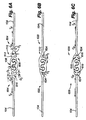
- the transition portions 112 of the fastening members 604 include a substantially crenellated pattern 608, including one or more substantially arced rectangular teeth 612 and substantially arced rectangular gaps 616.
- T F tensile force
- C F compression force
- the substantially rectangular arced teeth 612 and substantially arced rectangular gaps 616 are sized to have a similar unit thickness Dt, wherein the incorporation of these unit thickness Dt within the transition portion improve the extrusion process to provide a more even manufacturing process. That is, in general, an extrusion process is conducted by extruding molten plastic from a die. Because of the lack of flow restrictions, areas within the die of larger cross-sectional openings typically behave such that more molten plastic is extruded from the larger cross-sectional areas as compared to the areas having relatively smaller cross-sectional areas. By maintaining a substantially similar unit thickness Dt within the transition zone, a higher quality and/or more cost effective extrusion process is realized.
- the unit thickness Dt can also be used for elements of the tail portion 104 and head portion 108.
- Fig. 6B another embodiment of a pair of interlocked fastening members 620 is shown, wherein the fastening members include a longitudinal transition void 624.
- the longitudinal transition void 624 extends substantially the longitudinal length of the fastening members 620 within the transition portion 112, and serves, at least in part, to provide a similar unit thickness Dt to the elements forming the transition portion 112.
- the longitudinal transition void 624 comprises a substantially triangular shape in cross-section.
- Fig. 6C another embodiment of a pair of interlocked fastening members 628 is shown, wherein the fastening members 628 include a longitudinal transition void 624, and a set of gaps 616 to assist in isolating the mating surfaces from a tensile force T F , compression force C F , or fluid flow.
- Fig. 6D another embodiment of a pair of interlocked fastening members 632 is shown, wherein the fastening members 632 include a plurality of longitudinal transition voids 624, and a set of gaps 616 to assist in isolating the mating surfaces from a tensile force T F , compression force C F , or fluid flow.
- the longitudinal transition voids 624 vary in cross-sectional size and are substantially circular in cross-sectional shape, although as those skilled in the art will appreciate, other shapes can be used and are considered to be encompassed within the scope of the inventions and this description.
- Fig. 6E another embodiment of a pair of interlocked fastening members 636 is shown, wherein the fastening members include a longitudinal transition void 624, the longitudinal transition void 624 comprising a substantially circular shape in cross-section.
- FIG. 6F another embodiment of a pair of interlocked fastening members 640 is shown, including a plurality of substantially arced rectangular teeth 612 and substantially arced rectangular gaps 616.
- the plurality of substantially arced rectangular teeth 612 and substantially arced rectangular gaps 616 of Fig. 6F are oriented in a first direction, such as in a forward facing direction similar to the tongue and groove structures 128 of the respective head portions 108.
- FIG. 6G another embodiment of a pair of interlocked fastening members 644 are shown, including a plurality of substantially arced rectangular teeth 612 and substantially arced rectangular gaps 616.
- the sizing and number of the plurality of substantially arced rectangular teeth 612 and substantially arced rectangular gaps 616 of fastening member 644 varies from that of fastening member 640. Accordingly, the embodiments of the present inventions include all possible modifications encompassed within the scope of the disclosure and/or claims.
- the fastening members 648 include a longitudinally extending split 652 that passes from the exterior 656 of the transition portion 112 to an enlarged interior area 660.
- the fastening members 648 accommodate the application of a tensile force T without necessarily causing the mating surfaces 124 to disengage.
- the transition portion 112 of the fastening member 664 includes a curved portion 668 that can elongate in a direction perpendicular to the longitudinal axis of the fastening members 664.
- the amount of possible extension can be adjusted by using more curves or a sharper angled curved portion 668.
- stiffening of the curved portion 668 can be provided by forming the curved portion 668 of blocked portions 676, as shown in fastening members 678 of Fig. 6K .
- the curved portion 668 of the transition portion 112 can be seen engaging a top 680 of foot member 684, as shown in Fig. 6I , or a base 688 of foot member 684, as shown in Fig. 6J , where the foot member 684 includes an interior side 692 that contacts a tongue of the tongue and groove structures 128.
- the difference in location of the connection between the curved portion 668 and the foot member 684 influences the point of where the tensile force is applied at the mating surface 124.
- the valleys within the curved portions 668 provide a flow diversion for fluids around the mating surfaces 124.
- Fastening member 696 includes a more rounded substantially arced rectangular teeth 612 and substantially arced rectangular gaps 616 as compared to those shown in Fig. 6G .
- the cross members 704 are more rounded than those shown in Fig. 6H .
- FIGS. 6N-6Q additional fastening members 708, 712, 716 and 720 are shown, wherein the substantially arced rectangular gaps 616 of the transition portions 112 provide flow diversion from the mating surfaces 124.
- the substantially arced rectangular teeth 612 on a front side 116 of the fastening member are located opposite the substantially arced rectangular gaps 616 on the backside 120 of fastening member 708.
- the substantially arced rectangular teeth 612 on a front side 116 of the fastening member are located opposite the substantially arced rectangular teeth 612 on the backside 120 of fastening member 716.
- the transition portion 112 connects to the foot member 684 near a base 688 of the foot member 684, while for fastening member 716 of Fig. 6P , the transition portion 112 connects to the foot member 684 in line with the tail portion 104.
- a fastening member 740 that includes at least two different finishes on its exterior surface 744. More particularly, a glossy surface texture is preferably used within the area of the mating surface 124, while a matte fmish is used at the tail portion 104, the transition portion 112, and/or another area of the head portion 108. Varying the surface texture at different portions of the fastening member 740 provides greater performance for the overall closure.
- a glossy surface texture along the surface of the tongue and groove structures 128 of the mating surface 124 provides added protection against water/gas leakage, while having a matte finish along the backside 120 of the head portion 108 provides improved frictional interaction between a slider and the head portion 108.
- a fastening member 800 that includes tractioning features to provide increased engagement between opposing mating surfaces 124 of two interlocked fastening members 800. More particularly, and by way of example and not limitation, ridge and valleys 804 are provided along at least a portion of the mating surfaces 124 for frictional engagement between two fastening members 800. As shown in Fig. 8 , the ridge and valleys 804 are shown along substantially the top 808 of the tongues 812 of the tongue and groove structures 128. The ridge and valleys 804 are aligned with their long axis preferably substantially perpendicular to the longitudinal axis LA-LA of the fastening member 800.
- the ridge and valleys 804 of a first fastening member 800 engage the tongue and groove structures 128 of the second fastening member 800, thereby preventing or limiting longitudinal movement or slipping of the first fastening member 800 relative to the second fastening member 800.
- the ridge and valleys 804 may extend along the entire longitudinal length of the mating surfaces 124, or only extend along a portion of the longitudinal length of the mating surfaces. For example, areas having ridge and valleys 804 may be spaced apart.
- the grooves of a second fastening member include ridge and valleys 804 that engage the ridge and valleys along the top 808 of the tongues 812 of a first fastening member 800.
- a first fastening member includes one or more tongue and groove structures 128 that comprise a glossy surface finish, and one or more tongue and groove structures 128 that comprise the ridge and valleys 804.
- a second fastening member preferably includes one or more tongue and groove structures 128 that comprise a glossy surface for contacting the tongue and groove structures 128 of the first fastening member that have a corresponding glossy surface finish.
- one or more tongue and groove structures 128 of the second fastening member preferably comprise ridge and valleys 804 for contacting and frictionally engaging the tongue and groove structures 128 of the first fastening member that have corresponding ridge and valleys 804 surface texturing.
- ridge and valleys 804 for contacting and frictionally engaging the tongue and groove structures 128 of the first fastening member that have corresponding ridge and valleys 804 surface texturing.
- fastening members 900 that include a surface texturing 904 on the backside 120 of the head portion 108.
- the surface texturing enhances interaction or gripping of the fastening member 900 within a stop block 908.
- a textured surface 904 applied to the backside 120 of fastening member 900 interacts with the stop block 908 and provides gripping action that may otherwise only be provided by the stop block itself.
- the surface texturing 904 comprises ridge and valleys 912 having a long axis oriented preferably substantially perpendicular to the longitudinal axis LA-LA of the fastening member 900.
- the surface texturing 904 may extend down the entire longitudinal length of the backside 120 of the head portion 108, or only extend down a portion of the longitudinal length of the backside 120 of the head portion 108.
- the backside 120 of the head portion 108 having surface texturing 904 may be only located in area near the end of one of the fastening member 900 to engage the stop block 908, as shown in Fig. 9 .
- the surface texturing 904 may be formed when the fastening member 900 is extruded, or alternatively, it may be formed after extrusion, such as by using a tool that is applied to the backside 120 of the head portion 108.
- the surface texturing 904 may be added by applying (such as by gluing or welding) a separate member to the head portion 104, wherein the separate member comprises the surface texturing 904.
- fastening member 1000 includes a plurality of transversely oriented penetrating slits 1004; that is, at least some of the slits 1004 fully penetrate at least one of the tail portion 104, head portion 108 or transition portion 112.
- the slits 1004 are oriented substantially perpendicular to the longitudinal axis LA-LA of the fastening member 1000. The slits 1004 increase the flexibility of the fastening member 1000.
- the slits 1004 that are allowed to fully penetrate at least one of the tail portion 104, head portion 108 or transition portion 112 then those slits also will provide a means for ventilating the article to which the fastening member 1004 is associated with.
- the slits 1004 in the fastening member may be cut completely through the tail portion 104, head portion 108 and transition portion 112, and then the fastening member is restructured during the installation of the fastening member 1000 in the article to which it is associated with.
- fastening member 1000' includes a plurality of transversely oriented partially penetrating slits 1004'; that is, none of the slits 1004' fully penetrate the tail portion 104, head portion or transition portion 112.
- the slits 1004' may be limited to only certain portions of the fastening member 1000'.
- the slits 1004' are limited to the head portion 108 and transition portion 112, and are not extended into the tail portion 104.
- the slits 1004' increase the flexibility of the fastening member 1000'.
- fastening members 1200a and 1200b are shown that include one or more wires or electrical contacts 1204a and 1204b, respectively, extending at least a portion of the longitudinal length L of the fastening members 1200a and 1200b.
- the contacts 1204a and 1200b are located along a surface the tongue and groove structures 128 of the mating surfaces 124.
- the contacts 1204a and 1204b allow for electromagnetic radiation (e.g., electrical energy, radio waves, light, etc.) to be transferred from one fastening member 1200a to another fastening member 1200b.
- electromagnetic radiation e.g., electrical energy, radio waves, light, etc.
- fastening members 1220a and 1220b include one or more wires or electrical contacts 1224a and 1224b, respectively, extending within at least a portion of the longitudinal length L of the fastening members 1220a and 1220b.
- the electrical contacts 1224a and 1224b reside within the head portion 104, such as within a tongue of the tongue and groove structures 128.
- a contact bar can be provided in a stop block or other structure for interconnecting the electrical contacts 1224a and 1224b.
- wiring or another electromagnetic radiation conveyance structure can be incorporated within or surficially exposed into one or more the interlocking fastening members.
- the tail portion 104 of a fastening member can have a woven fiber inlayed invisibly under its surface to provide strength, while the mating surface has wiring mounted above or within the tongue and groove structures 128 to provide a direct wiring contact that electromagnetically communicates with corresponding wiring from the interlocking fastening member.
- ballistic protective fabrics can be used within the article, with fiber optics or other communication elements residing within the mating surfaces 124 of the closure of the article to provide a communication link between a soldier's headset and a communication system or other device attached or interconnected elsewhere to the soldier's body.
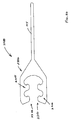
- fastening member 1600 that comprises structure for resisting disengagement from a corresponding fastening member 1600 when under the influence of tensile or compression forces in a direction transverse to the longitudinal axis LA-LA of the fastening members 1600.
- the fastening member 1600 is intended to be used with an identical fastening member 1600, or with a fastening member whose mating surface 124 is similar in geometry to fastening member 1600.
- the mating surface 124 of fastening member 1600 has relatively larger tongue and groove structures 128 that help stabilize and prevent premature disengagement of the mating surfaces 124.
- the fastening member 1600 includes a rotation preventer that assists in maintaining the interlocked position of the mating surfaces 124 when the interlocked mating surfaces experience a tensile force or compression force that is transverse to the longitudinal axis LA-LA of the fastening members 1600, because the geometry of the mating surfaces 124 tend to keep the tips of the tongues of the tongue and groove structures 128 interlocked.
- the fastening member 1600 includes a head portion 108 including a front side 116 and a backside 120.
- the front side 116 includes mating surface 124 comprising a plurality of tongue and groove structures 128, wherein an outermost tongue 1604 includes a rotational preventer 1608 comprising an extension 1612 having a sloping terminal surface 1616.
- the sloping terminal surface 1616 defines a sloping terminal surface plane 1620 extending from the sloping terminal surface 1616, wherein the sloping terminal surface plane 1620 intercepts a backside plane 1624 at an angle ⁇ , where the backside plane 1624 is coplanar with the exterior surface 1628 of the backside 120.
- ⁇ is preferably less than 90 degrees, and more preferably, ⁇ is between about 55 to 75 degrees, and more preferably yet, ⁇ is between about 60 to 70 degrees. It is noted that a number of embodiments of the present inventions described herein may optionally include the rotational preventer 1608, and this feature has been identified by its reference number in the various figures. Accordingly, the rotational preventer 1608 and the geometry described within this paragraph are applicable as an option and/or in combination with numerous other inventive aspects described herein.
- the tail portion 104 comprises a planar surface 1632 that is substantially parallel to the backside plane 1624.
- the transitional portion 112 includes an interior transitional surface 1636 having a height H, wherein the interior transitional surface 1636 is substantially parallel to the sloping terminal surface 1616.
- the interior transitional surface 1636 corresponds to an innermost groove surface of the plurality of tongue and groove structures 128.
- the tail portion 104 includes a tail upper surface 1640 and a tail lower surface 1644.
- the tail upper surface 1640 is substantially parallel to the tail lower surface 1644.
- the tail upper surface 1640 is spaced apart from the tail lower surface 1644 to define a tail thickness T, where the tail thickness T is less than the height H of the interior transitional surface 1636.
- a lower tail plane 1648 coplanar with the tail lower surface 1644 and extending from the tail lower surface 1644 through the head portion 108 intercepts the sloping terminal surface 1616 at the angle ⁇ , where ⁇ is defined as above the lower tail plane 1648 (that is, toward the front side 116 of the head portion 108).
- the backside plane 1624 is substantially parallel to the lower tail plane 1648.
- the outermost tongue 1604 has at least one tip 1652, and a tip plane 1656 coplanar with an underside surface 1660 of the at least one tip 1652 intersects the sloping terminal surface 1616 at an angle ⁇ when the tip plane 1656 is extended through the outermost tongue 1604, wherein ⁇ is measured below the tip plane 1656.
- ⁇ is preferably between about 85 to 95 degrees.
- the tail portion 104 of the fastening members 1600 may optionally include a tapered terminal surface 1664.
- the tapered terminal surface 1664 may face up or down. As shown in Fig. 16 , the tapered terminal surface 1664 allows for an even integration of the fastening member 1600 with a panel 1668 of the article to which the fastening member 1600 is to be attached.
- the tapered terminal surface 1664 may be bonded to panel 1668, thereby providing a smooth transition between the tail portion 104 and the panel 1668, particularly if the panel includes a matching slope surface 1672 for attachment to the tapered terminal surface 1664 of fastening member 1600.
- other techniques may be used to attach fastening members to various articles, including but not limited to, gluing, welding, fastening, molding, etc.
- the tapered terminal surface 1664 provides advantages for at least some of these techniques.
- the tail portion 104 of the various fastening members described herein may alternatively comprise a tip 1676 that includes twin sloped surfaces 1680.
- the twin sloped surfaces 1680 of tip 1676 can aid in the installation of the fastening member into various articles, such as garments.
- a fastening member is shown as an interlocked pair comprising identical fastening members 1800a and 1800b.
- Each fastening member includes a plurality of tongues that further include a plurality of tips.
- first tongue 1804a includes upper tip 1812a and lower tip 1816a.
- second tongue 1808a includes upper tip 1820a and lower tip 1824a.
- fastening member 1800b includes first tongue 1804b that includes upper tip 1812b and lower tip 1816b.
- second tongue 1808b includes upper tip 1820b and lower tip 1824b.
- a fastening system 1900 that comprises a first fastening member 1600 and a second fastening member 1904.
- the second fastening member 1904 includes a mating surface 124 that releasably interlocks with mating surface 124 of fastening member 1600.
- second fastening member 1904 includes a backside 120 that features a receptacle 1908 for receiving an insert 1912.
- the receptacle 1908 comprises a groove 1916 that is adapted for interlockingly receiving a tongue 1920 of the insert 1912.
- the insert 1912 may be a variety of structures.
- the insert 1912 may comprise one or more of a reflector, a fluid conveyance conduit, a wire, a communication element, a bumper, and a decorative insert.
- Such inserts 1912 have application for use with a closure that is associated with an article, such as a jacket. When used with a jacket or other applicable article, the closure may be opened and closed with a slider.
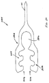
- a fastening system 2300 that includes a plurality of releasably interlocking mating surfaces. More particularly, as best seen in Figs. 24 and 25 , the fastening system 2300 includes a first fastening member 2304 including a head portion 2308 having a primary mating surface 2312 on a first or front side 2316 and a secondary mating surface 2320 on a second or backside 2324. In addition, as best seen in Figs. 26 and 27 , the first fastening member 2304 is received within a second fastening member 2328 that includes a forked head portion 2332.
- the forked head portion 2332 includes a first interior side 2336 having a first interior mating surface 2340 and an opposing second interior side 2344 having a second interior mating surface 2348.
- the head portion 2308 of the first fastening member 2304 is adapted for being releasably interlocked in the forked head portion 2332 of the second fastening member 2328.
- the primary mating surface 2312 of the head portion 2308 releasably interlocks with the first interior mating surface 2340 of the forked head portion 2332
- the secondary mating surface 2320 of the head portion 2308 releasably interlocks with the second interior mating surface 2348 of the forked head portion 2332.
- a fastening system 2800 that includes first fastening member 2304 and a second fastening member 2804 having a forked head portion 2308 that includes a void space 2812. Similar to forked head portion 2332 of second fastening member 2328, and as best seen in Figs. 29 and 30 , the forked head portion 2808 of second fastening member 2804 includes a first interior side 2336 having a first interior mating surface 2340 and an opposing second interior side 2344 having a second interior mating surface 2348. In addition, an interior pocket 2816 is located adjacent the first and second interior mating surfaces 2340, 2348.
- the void space 2812 of the fastening system 2800 can serve several purposes, including providing increased bending qualities and flexibility to the interlocked first and second fastening members 2304, 2804.
- the void space 2812 may be pressure tested to document an airtight (or liquid tight) closure, and/or monitored for liquid or gas leakage.
- the void space 2812 can serve as a conduit for a fluid.
- the slider 3100 for use with the fastening system 2300 and 2800 is shown.
- the slider 3100 generally includes an opening end 3104 and a closing end 3108.
- the head portion 2308 of first fastening member 2304 is inserted into a first side 3112 of the slider 3100, and the forked head portion 2332 of the second fastening member 2328 is inserted into a second side 3116 of the slider 3100.
- the mating surfaces of the first and second fastening members 2304 and 2328 are brought into interlocking engagement when the slider 3100 is moved in a closing direction.
- the first fastening member 2304 is disengaged from the second fastening member 2328.
- a multi-layer fastening system 3200 that includes a plurality of releasably interlocking mating surfaces. More particularly, the multi-layer fastening system 3200 includes first and second fastening members 3400a, 3400b, as well as cap member 3500a and base member 3500b.
- the first and second fastening members 3400 include a head portion 3404 having a primary mating surface 3408 on a front side 3412, and a secondary mating surface 3416 on a backside 3420.
- the head portion 3404 also has an extension 3424 that includes a tertiary mating surface 3428.
- the cap member and base member 3500 have a first cap/base mating surface 3504 and a spaced apart second cap/base mating surface 3508.
- the first cap mating surface 3504a is adapted to releasably interlock with the first primary mating surface 3408a of the first fastening member 3400a
- the second cap mating surface 3508a adapted to releasably interlock with the second primary mating surface 3408b of the second fastening member 3400b
- the base member 3500b includes a first base mating surface 3504b adapted to releasably interlock with the first secondary mating surface 3416a of the first fastening member 3400a
- the second base mating surface 3508b is adapted to releasably interlock with the second secondary mating surface 3416b of the second fastening member 3400b.
- the tertiary mating surface 3428a of the first fastening member 3400a is adapted to releasably interlock with the tertiary mating surface 3428b of the second fastening member 3400b, thereby forming an intermediate seal 3204.
- the cap member 3500a bounds the intermediate seal 3204 on a first side 3208
- the base member 3500b bounds the intermediate seal 3204 on a second side 3212.
- a first void space 3216 is formed between the intermediate seal 3204 and an interior side 3220 of the cap member 3500a.
- a second void space 3224 is formed between the intermediate seal 3204 and an interior side 3228 of the base member 3500b.
- the void spaces 3216 and 3224 of the fastening system 3200 can serve several purposes, including allowing one or both of the void spaces 3216 and 3224 to be pressure tested to document an airtight (or liquid tight) closure, and/or monitored for liquid or gas leakage.
- one or both the void spaces 3216 and 3224 can serve as a conduit for a fluid, such as water, or one or both the void spaces 3216 and 3224 can receive another material, such as a sealant.
- another multi-layer fastening system 3600 that includes a plurality of releasably interlocking mating surfaces. More particularly, the multi-layer fastening system 3600 includes a plurality of members having interlocking mating surfaces that can be arranged in a stacked manner.
- the multi-layer fastening system 3600 includes two fastening members 2304 that are stacked and interconnected by fastening member 3700.
- fastening member 3700 includes a forked head portion 3704 that includes a first fork member 3708 having a first interior side 3712 and an exterior side 3716, wherein the first interior side 3712 includes a first interior side mating surface 3720, and the exterior side 3716 includes an exterior side mating surface 3724.
- the forked head portion 3704 includes a second fork member 3728 having a second interior side 3732 including a second interior side mating surface 3736.
- the backside 3738 of the second forked member 3728 does not have a mating surface, although if desired, a mating surface can be provided on the backside 3738 for allowing an additional fastening member to be attached to the backside 3738.
- a mating surface can be provided on the backside 3738 for allowing an additional fastening member to be attached to the backside 3738.
- an interior pocket 3740 is also present (although such a feature is optional) that allows for formation of a void space 3604 when assembled as shown in Fig. 36 .
- the two tail portions 104 that are aligned on the right side of the page are associated with fastening members 1904 and 3700, and the two tail portions 104 aligned on the left side of the page are associated with fastening members 2304.
- Such a configuration at least has application for jackets or bags with various liners and/or exterior shells.
- fastening members and/or their associated features shown in Figs. 1-38 may be combined in a variety of different manners, and such configurations are considered within the scope of the present inventions. That is, the ability to stack and/or combine fastening members and/or combine inventive aspects can be appreciated, and thus, one or more aspects of one embodiment may be combined with one or more aspects of one or more other embodiments.
- a slider 3900 that includes a slider body 3904 having an opening end 3908 and a closing end 3912.
- the slider 3900 is used to open and close two fastening members that each have a mating surface.
- the slider 3900 forces the mating surfaces together when the slider 3900 is moved in its closing direction, and the slider 3900 separates the mating surfaces when the slider is moved in its opening direction.
- the opening end 3908 of slider 3900 includes an upper portion 3916 and a lower portion 3920, and an intermediate portion 3924 located between the upper and lower portions 3916, 3920.
- the intermediate portion 3924 is positioned generally at the opening end 3908 for locating between a first mating surface of a first fastening member and a second mating surface of a second fastening member when the slider 3900 is moved in an opening direction.
- the slider body 3904 comprises pathways through which the fastening members slide during the opening or closing movement of the slider 3900.
- the slider 3900 provides a pathway that is substantially straight along the longitudinal axis LA-LA of the mating surface of the second fastening member.
- Slider 3900 has application for use where the second fastening member is relatively stiff (e.g., metal, hard plastic, etc.) while the other fastening member is flexible.
- the second fastening member is relatively stiff (e.g., metal, hard plastic, etc.) while the other fastening member is flexible.
- such an application may include an awning or cover for a boat.
- the interlock shape or mating surface for the second fastening member for the boat portion can be hard and molded directly to the boat, and the flexible cover or awning comprising the flexible first fastening member can be interlocked to the boat by translation of the slider 3900 around the applicable portion of the boat, thereby interlocking the first flexible fastening member to the relatively hard and stiff second fastening member.
- a fastening system 4000 that includes a slider 4004 that uses magnetism to interact with fastening members 4008a and 4008b.
- the fastening system 4000 includes a first fastening member 4008a having a first head portion 108a that includes a first mating surface 124a.
- the first head portion 108a includes a ferromagnetic material extending along a longitudinal length of the first mating surface 124a.
- the fastening system 4000 also includes a second fastening member 4008b having a second head portion 108b that includes a second mating surface 124b, wherein the second mating surface 124b is adapted for releasably interlocking with the first mating surface 124a.
- the slider 4004 is moved along the longitudinal axis LA-LA of the head portions 108a and 108b.
- the slider 4004 comprises a slider body 4012 having an opening end 4016 and a closing end 4020.
- the opening end 4016 has an upper portion 4024 and a lower portion 4028.
- the closing end 4020 has an upper portion 4032 and a lower portion 4036.
- the upper portion 4024 and the lower portion 4028 each include a slider magnet wherein a magnetic force is applied between the first head portion 108a and the upper portion 4024, and between the second head portion 108b and the lower portion 4028 at the opening end 4016 to pull the mating surfaces 124a and 124b apart.
- the slider magnets preferably extend along at least a portion of the length of the slider body 4012 so that when pulled in the opening direction, the slider magnets initiate separation of the mating surfaces 124a and 124b within the interior region of the slider body 4012.
- the slider 4004 may include an intermediate portion 4040, and in at least one embodiment, the intermediate portion 4040 is discontinuous across the width of the slider body 4012, such that a first intermediate portion 4044 is situated opposite a second intermediate portion 4048.
- the head portion 108a of the first fastening member 4008a resides between the intermediate portion 4040 and the upper portion 4024 at the opening end 4016, and the head portion 108b of the second fastening member 4008b resides between the intermediate portion 4040 and the lower portion 4028.
- the intermediate portion 4040 may also optionally include at least one magnet or ferromagnetic material.
- the orientation of magnets within the slider body 4012 may include magnets to induce separation of the head portions 108a and 108b within the middle interior of the slider body 4012 and toward the opening end 4016 of the slider body, while magnets may be used to push together the mating surfaces 124a and 124b within the middle interior of the slider body 4012 and toward the closing end 4020.
- the closing end 4020 of the slider body 4012 may not comprise a magnet and/or a ferromagnetic material.
- the head portions 108a and 108b may use magnets and/or ferromagnetic materials to improve the interaction with not only the slider 4004, but also with each other, such that the first head portion 108a and the second head portion 108b are magnetically attractive.
- magnets and/or ferromagnetic materials can be extruded directly into the head portions 108a and 108b, and/or they may be attached as an insert 1912, or they may be attached by an adhesive. At least part of one of the head portions 108a and 108b can be removed at a longitudinal end of the fastening member to provide an airtight and/or water tight closure.
- a multi-piece slider 4200 is shown that at least has application for repair situations where a slider has broken and a replacement one-piece slider cannot be inserted into the fastening members.
- the slider 4200 is generally anticipated for use with a first fastening member and a second fastening member that each include a mating surface.
- the slider 4200 includes a slider body 4204 having a plurality of portions adapted for interconnection using a fastening mechanism 4210.
- the slider body 4204 may include an intermediate portion 4208 that is separable and interconnectable, such as by a rod, latch, screw, bolt, etc.
- a first portion 4212 of the slider body 4204 is interconnected to a second portion 4216 of the slider body 4204.
- a fastening mechanism 4210 serves to join the first intermediate portion 4208a of the first portion 4212 to the second intermediate portion 4208b of the second portion 4216. Similar to sliders described above, when assembled, the intermediate portion 4208 serves to separate the mating surfaces upon translation of the slider in an opening direction. When assembling the slider 4200 to repair a broken slider, the broken slider is first removed from the first and second fastening members.
- the slider 4200 is then attached to the first and second fastening members by inserting the head portion of the first fastening member above the first intermediate portion 4208a, then inserting the head portion of the second fasten member below the intermediate portion 4208b, and then securing the first portion 4212 of the slider body 4204 to the second portion 4216 of the slider body 4204 by engaging the fastening mechanism 4210 to interconnect the first intermediate portion 4208a to the second intermediate portion4208b.
- a slider 4400 that includes a slider body 4404 having at least one roller that eases friction between at least one fastening member and the slider 4400. More particularly, one or more rollers 4408 are operatively associated with the slider body 4404 and serve to assist in reducing friction as the slider 4400 is moved to close or open the mating surfaces of the fastening members. With reference to Fig. 44 , a roller 4408 is located on an inside surface 4412 of an intermediate portion 4416 of the slider body 4404.
- the roller 4408 may comprise a cylindrical shaped device, a more narrow wheel-shaped device, or a spherical shaped device, such as a ball bearing.
- the rollers 4408 are located to contact both the first and second fastening members.
- the roller 4408 has a rotational axis RA-RA oriented substantially perpendicular to the longitudinal axis LA-LA.
- a slider 4500 that comprises exterior rollers 4504 for engaging the tail portions 104 of the fastening members.
- the exterior rollers 4504 assist with limiting frictional interaction of the fastening members as the slider 4500 is moved longitudinally.
- the slider 4500 may also optionally include one or more rollers 4408, such as the roller 4408 shown at the top of the intermediate portion 4416.
- a slider 4600 is shown that is configured for receiving inserts to provide additional functionality. More particularly, the slider 4600 includes a section slider insert system that allows for different materials to be incorporated into the slider for various reasons. One such reason is to add self-lubricating plastic inserts, such as Teflon inserts to provide a combination of strength and ease of slider interaction with the head portions of the fastening members as the head portions pass through the slider. Alternatively, the insert or inserts may comprise a magnet for interaction with appropriate fastening members. Additionally, the interconnectivity of the various components allows for a complex multi-piece slider to be more easily manufactured.
- the sections of the slider 4600 can be snapped together, glued together, or interconnected using fasteners, such as screws. Inserts can also be added to other devices described herein, such as stop blocks. For example, a new or alternative gripping element can be added to a stop block.
- the slider 4600 includes a slider body 4604 having an upper portion 4608, a lower portion 4612, and an intermediate portion 4616 between the upper portion 4608 and lower portion 4612.
- the intermediate portion 4616 at the opening end 4620 of the slider body 4604 is located between the pathways which the fastening members slide during the opening or closing movement of the slider 4600.
- the intermediate portion has a first side 4624 that is releasably interconnectable to the upper portion 4608, and a second side 4628 that is releasably interconnectable to the lower portion 4612. Accordingly, the intermediate portion 4616 can be separated from the upper portion 4608 and lower portion 4612.
- the intermediate portion 4616 is replaceable with removal from the upper and lower portions 4608, 4612, and insertion of a replacement intermediate portion.
- the new intermediate portion 4616 may include a self-lubricating element for contacting at least one of the fastening members.
- Figs. 48 and 49 an insert member 4800 is shown that can be inserted into slider 4600 to form a portion of the slider body 4604.
- a slider 5000 that includes pull tab system 5004.
- the Pull tab system 5004 comprises a rotatably mounted pull tab 5008 that is interconnected to the slider body 5012 at the intermediate portion 5016.
- the location of the interconnection at the intermediate portion 5016 allows the pull tab 5008 to be drawn in both the opening direction and closing direction such that the forces applied are more in-line with the longitudinal axis of the fastening members, thereby more effectively moving the slider 5000 and also lessening unnecessary forces from acting on the mating surfaces of the fastening members.
- the rotatably mounted pull tab 5008 is interconnected to the intermediate portion 5016 by a pin 5020 located at the opening end 5024 of the slider body.
- Fig. 52 illustrates an example embodiment of pin 5020, which generally comprises a cylindrical shaped rod.
- the pin 5020 of the pull tab system 5004 may optionally include a wedge 5300 as shown in Fig. 53 , wherein the wedge 5300 is fixedly attached to the pin 5020.
- the wedge 5300 is preferably located within the interior of the slider 5000, wherein the wedge 5300 is able to contact and frictionally engage at least a portion of least one of the fastening members, such as a head portion of one of the fastening members.
- rotation of the pull tab 5008 down also rotates the wedge 5300 against a fastening member to force the fastening member against an interior surface of the slider body 5012, thereby releasably locking the longitudinal position of the slider 5000 against at least one of the fastening members.
- the pull tab 5008 is lifted up and then pulled in the desired direction.
- an upper wedge may be situated in the upper portion of the slider body, wherein rotation of a connected tab rotates the upper wedge downward against the fastening member to releasably lock the fastening member, such as by forcing the fastening member in contact with an interior upper surface of the intermediate portion.
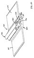
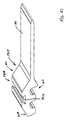
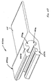
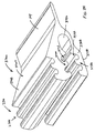
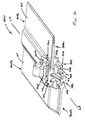
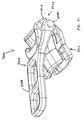
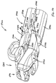
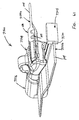
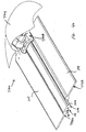
- a slider and stop block combination 5400 is shown that includes a slider 5404 and a stop block 5408.
- This combination of devices is particularly useful for articles such as jackets; however, it may also be used in other articles, including but not limited to, sleeping bags, removable pant legs, removable hoods, etc.
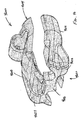
- the slider 5404 comprises a slider body 5412 including an opening end 5416 and a closing end 5420.
- the closing end 5420 includes a confining portion 5424 that functions to confine the first mating surface 124 of a first fastening member into interlocking engagement with a second mating surface 124 of a second fastening member.
- the closing end 5420 of the slider body 5412 includes an upper sloping surface 5428 and a lower sloping surface 5432 that resemble a truncated wedge when viewed from the side, as seen in Fig. 54 .
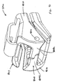
- the stop block 5408 includes structural features to hold and release a fastening member, and to interact with the slider 5404.
- the stop block 5408 includes a first housing portion or upper housing portion 5436 and a second housing portion or lower housing portion 5440.
- the lower housing portion 5440 is permanently secured to one of the first and second fastening members, such as at a longitudinal end of a fastening member.
- the upper housing portion 5436 is preferably movably connected to the lower housing portion 5440, and more preferably, the upper housing portion 5436 is hingedly interconnected to the lower housing portion 5440 by hinge 5444.
- the upper housing portion 5436 includes an upper sloping receiving surface 5448
- the lower housing portion 5440 includes a lower sloping receiving surface 5452.
- the stop block 5408 has a first closed position (as shown in Fig. 54 ) and a second open position.
- first closed position as shown in Fig. 54
- second open position When the upper and lower sloping surfaces 5428 and 5432 of the slider 5404 contact the upper and lower sloping receiving surfaces 5448 and 5452 of the stop block 5408, the slider 5404 urges the stop block 5408 from the first closed position to the second open position. That is, the upper housing portion 5436 moves along arrow A to rotate its front end 5450 upward to the second open position. In so doing, the stop block 5408 allows at least a grasp portion of the unsecured fastening member to be fed into the stop block 5408 while the stop block is in the second open position.
- the slider 5404 is then advanced in the closing direction away from the stop block 5408 placing the stop block 5408 back in the first closed position.
- the stop block 5408 automatically closes because the upper portion 5436 is normally biased in its closed position, such as by a spring.
- the grasp portion of the inserted fastening members is held in place by the stop block 5408, such as by use of gripping elements 5456 located within the interior 5460 of the stop block 5408.
- An optional latch 5464 (shown with dashed lines in Fig. 54 ) may be provided to selectively lock the upper housing portion 5436 to the lower housing portion 5440 when the stop block 5408 is closed, thereby locking the stop block in its closed position.
- the closing end 5412 of the slider 5404 contacts the forward end 5416 of the stop block 5408, thereby allowing the user to insert the fastening member that is not permanently attached to the stop block 5408 into the stop block interior 5420.
- the user then moves the slider 5404 away from the stop block 5408 in the closing direction to releasably interlock the mating surfaces 124 of the first and second fastening members.
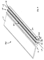
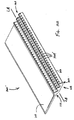
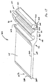
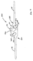
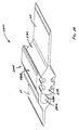
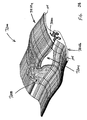
- fastening system 7100 that includes top stop 7104.
- top stop 7104 In general, to stops are used to prevent the slider from leaving the end (or top) of the closure.
- Fastening system 7100 includes first fastening member 7108a and second fastening member 7108b.
- top stop 7104 includes two separable portions, a right top stop portion 7112a and a left top stop portion 7112b, wherein the right top stop portion 7112a is fixedly attached to the first fastening member 7108a, and the left top stop portion 7112b is fixedly attached to the second fastening member 7108b.
- the right top stop portion 7112a is brought together with the left top stop portion 7112b.
- Such a configuration not only serves to keep the slider 7116 from leaving the fastening members7108a and 7108b, but also serves to provide a structurally smooth and visually appealing end to the closure.
- the structurally smooth finish improves user satisfaction, because for a jacket the top stop 7104 prevents possible irritation or chaffing of the user's chin or neck from the end of the closure.
- the top stop 7104 may optionally include a frictionally engaging clasp for releasably securing the slider 7116 to the top stop 7104.
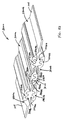
- fastening system 7200 that includes a top stop 7204, slider 7208 and first and second fastening members 7212a and 7212b.
- the slider 7208 can be advanced to the top stop 7204 for releasably interlocking with the with top stop 7104.
- the top stop 7204 is shown without the slider 7208 and without the first fastening member 7212a.
- the top stop 7204 includes a top stop mating surface 7216 that mates with the mating surface 7220 of the first fastening member 7212a when the slider 7208 is advanced to the top stop 7204.
- the slider 7208 brings the mating surface 7220 of the first fastening member 7212a into contact with the top stop mating surface 7216 by overlying the top stop 7204.
- the top stop mating surface 7216 includes tongue and groove structures 7224 for releasably engaging the mating surface 7220 of the first fastening member 7212a.
- the slider 7208 of fastening system 7200 may optionally include tongue and groove structures for mating with the tongue and groove structures 7224 of the top stop 7204. Such configuration can prevent air, water, or gas penetration though the closing mating surfaces that are formed around the slider 7208, as well as prevent leakage around the first and second fastening members 7212a and 7212b, and top stop 7204.
- fastening system 7500 includes a top stop 7504, slider 7508, first and second fastening members 7512a and 7512b, and stop block 7516.
- the top stop 7504 is located on only one fastening member, that is, fastening member 7512b.
- Such a top stop 7504 can be a piece of material, such a plastic, that is molded and permanently attached to the longitudinal end 7520 of the second fastening member 7512b.
- fastening system 7700 includes a slider garage 7704 for receiving the slider 7708 when the slider is located at a longitudinal end 7712 of the fastening members 7716a and 7716b.
- the slider garage 7704 can be a variety of materials, included a molded plastic or metal hood, or a portion of the article to which the closure is attached, such as a flap of material.
- the motorized slider 7900 preferably includes a motor 7904 operatively associated with a slider body 7908.
- the motor can be used to power the slider body 7908 and/or rotate drums 7912 for advancing the fastening members within the slider body 7908.
- the motorized slider 7900 can be used to automatically close fastening members, including fastening members that are associated with waterproof field covers for stadiums. In use, the user would line up the large rolls of material for covering the field and activate the motorized sliders 7900 to traverse the field to automatically join the large panels with watertight closures while simultaneously unrolling the covers into position.
- stop blocks and/or top stops described herein may include magnets or ferromagnetic materials for interaction with the head portions 108 of the fastening members.
- the stop blocks and top stops described herein may further include electronic elements, such as wiring, fiber optics, and/or a battery for forming part of the operable elements associated with appropriate fastening members and/or certain of their components, such as fastening members 1200a, 1200b, 1220a, and 1220b shown in Figs. 12-15 .
- the materials forming the stop blocks and top stops can comprise plastic, metal, glass, ceramic, combinations thereof, etc.
- Such structures may also include inserts, such as reflective features.
Landscapes
- Engineering & Computer Science (AREA)
- Mechanical Engineering (AREA)
- Connection Of Plates (AREA)
- Slide Fasteners (AREA)
- Clamps And Clips (AREA)
Claims (6)
- Befestigungssystem, das aufweist:ein erstes Befestigungselement (100), das eine erste Eingriffsfläche (124) umfasst, wobei das erste Befestigungselement ein erstes Längsende und ein zweites Längsende aufweist, wobei sich die erste Eingriffsfläche über eine erste Länge in der Längsrichtung zwischen dem ersten und dem zweiten Längsende des ersten Befestigungselementes erstreckt;ein zweites Befestigungselement (100), das eine zweite Eingriffsfläche (124) umfasst, wobei das zweite Befestigungselement ein erstes Längsende und ein zweites Längsende aufweist, wobei sich die zweite Eingriffsfläche über eine zweite Länge in der Längsrichtung zwischen dem ersten und dem zweiten Längsende des zweiten Befestigungselementes erstreckt, und wobei die zweite Eingriffsfläche dafür ausgebildet ist, dass sie im Allgemeinen entgegengesetzt der ersten Eingriffsfläche positioniert wird, um die erste Eingriffsfläche lösbar zu verriegeln; undeinen Schieber (5404), der einen Schieberkörper (5412) einschließlich eines Öffnungsendes (5416) und eines Schließendes (5420) aufweist, wobei das Schließende einen eingrenzenden Abschnitt (5424) aufweist, wobei die erste Eingriffsfläche des ersten Befestigungselementes in einem verriegelnden Eingriff mit der zweiten Eingriffsfläche des zweiten Befestigungselementes angeordnet wird, wobei, wenn der Schieber in einer Schließrichtung bewegt wird, das erste Befestigungselement und das zweite Befestigungselement innerhalb des Schiebers vom Öffnungsende zum Schließende gelangen und der Schieber die erste Eingriffsfläche in einem verriegelnden Eingriff mit der zweiten Eingriffsfläche anordnet, dadurch gekennzeichnet, dass mindestens ein Abschnitt des Schieberkörpers eine schräge Eingriffsfläche (5428, 5432) an seinem Schließende aufweist, und dadurch, dass das Befestigungssystem außerdem einen Anschlagblock (5408) aufweist, der einen ersten Gehäuseabschnitt (5436) und einen zweiten Gehäuseabschnitt (5440) aufweist, wobei der erste Gehäuseabschnitt gelenkig mit dem zweiten Gehäuseabschnitt verbunden ist (5444), wobei einer von erstem und zweitem Gehäuseabschnitt stationär an mindestens einem von erstem und zweitem Längsende des einen von erstem und zweitem Befestigungselement gesichert ist, wobei der Anschlagblock mindestens eine erste geschlossene Position und eine zweite offene Position aufweist, wobei, wenn die schräge Eingriffsfläche des Schieberkörpers eine Aufnahmefläche (5448, 5452) von mindestens einem von erstem und zweitem Gehäuseabschnitt des Anschlagblockes berührt, der Schieber den Anschlagblock aus der ersten geschlossenen Position in die zweite offene Position treibt, wobei der Anschlagblock lösbar mindestens einen Greifabschnitt eines weiteren des mindestens einen von erstem und zweitem Längsende des einen von erstem und zweitem Befestigungselement innerhalb des Anschlagblockes sichert, wenn der Greifabschnitt in den Anschlagblock in der zweiten offenen Position eingeführt wird und der Schieber danach in der Schließrichtung weg vom Anschlagblock vorwärtsbewegt wird, wobei der Anschlagblock in der ersten geschlossenen Position angeordnet wird.
- Befestigungssystem nach Anspruch 1, bei dem das Schließende des Schieberkörpers eine Keilform aufweist.
- Befestigungssystem nach Anspruch 2, bei dem der Anschlagblock eine innere Fläche aufweist, die eine Vielzahl von gerippten Eingriffsflächen umfasst.
- Befestigungssystem nach Anspruch 1, das außerdem einen oberen Anschlag (7204) aufweist, der stationär an mindestens einem von erstem und zweitem Längsende des einen von erstem und zweitem Befestigungselement gesichert ist.
- Befestigungssystem nach Anspruch 4, bei dem der obere Anschlag eine Eingriffsfläche (7216) aufweist, wobei der Schieber einen Feder- und Nutabschnitt aufweist, und bei dem die Eingriffsfläche des oberen Anschlages so ausgebildet ist, dass sie mit dem Feder- und Nutabschnitt des Schiebers in Eingriff kommt.
- Befestigungssystem nach Anspruch 4, das außerdem einen elektrischen Draht aufweist, der innerhalb von mindestens einem von erstem Befestigungselement, zweitem Befestigungselement, Anschlagblock und oberem Anschlag angeordnet ist.
Priority Applications (1)
| Application Number | Priority Date | Filing Date | Title |
|---|---|---|---|
| EP11005889A EP2397043A3 (de) | 2006-11-19 | 2007-11-19 | Vorrichtung zur Herstellung eines Verschlusses zwischen Textilstoffe und/oder anderen Materialien |
Applications Claiming Priority (2)
| Application Number | Priority Date | Filing Date | Title |
|---|---|---|---|
| US86642706P | 2006-11-19 | 2006-11-19 | |
| PCT/US2007/085127 WO2008064170A2 (en) | 2006-11-19 | 2007-11-19 | Devices and methods for forming a closure between fabrics and/or other materials |
Related Child Applications (1)
| Application Number | Title | Priority Date | Filing Date |
|---|---|---|---|
| EP11005889.8 Division-Into | 2011-07-19 |
Publications (3)
| Publication Number | Publication Date |
|---|---|
| EP2091374A2 EP2091374A2 (de) | 2009-08-26 |
| EP2091374A4 EP2091374A4 (de) | 2011-01-26 |
| EP2091374B1 true EP2091374B1 (de) | 2013-08-28 |
Family
ID=39430540
Family Applications (2)
| Application Number | Title | Priority Date | Filing Date |
|---|---|---|---|
| EP07864613.0A Not-in-force EP2091374B1 (de) | 2006-11-19 | 2007-11-19 | Vorrichtungen zur herstellung eines verschlusses zwischen textilstoffen und/oder anderen materialien |
| EP11005889A Withdrawn EP2397043A3 (de) | 2006-11-19 | 2007-11-19 | Vorrichtung zur Herstellung eines Verschlusses zwischen Textilstoffe und/oder anderen Materialien |
Family Applications After (1)
| Application Number | Title | Priority Date | Filing Date |
|---|---|---|---|
| EP11005889A Withdrawn EP2397043A3 (de) | 2006-11-19 | 2007-11-19 | Vorrichtung zur Herstellung eines Verschlusses zwischen Textilstoffe und/oder anderen Materialien |
Country Status (7)
| Country | Link |
|---|---|
| US (1) | US20080124008A1 (de) |
| EP (2) | EP2091374B1 (de) |
| JP (1) | JP2010510004A (de) |
| KR (1) | KR20090086436A (de) |
| CN (1) | CN101657121B (de) |
| CA (1) | CA2670108C (de) |
| WO (1) | WO2008064170A2 (de) |
Cited By (1)
| Publication number | Priority date | Publication date | Assignee | Title |
|---|---|---|---|---|
| EP4076084A1 (de) * | 2019-12-20 | 2022-10-26 | Geox S.p.A. | Leuchtvorrichtung und sohlenstruktur, die diese leuchtvorrichtung umfasst |
Families Citing this family (20)
| Publication number | Priority date | Publication date | Assignee | Title |
|---|---|---|---|---|
| US6721999B2 (en) * | 2001-04-30 | 2004-04-20 | Absolute Closure Innovations, Inc. | Device for creating a seal between fabrics or other materials |
| CA2700166A1 (en) * | 2007-09-25 | 2009-04-02 | Gore Enterprise Holdings, Inc. | Self-lubricating fasteners |
| FR2966442B1 (fr) * | 2010-10-20 | 2014-02-07 | S2F Flexico | Dispositif de fermeture, et sachet en faisant usage |
| JP5953043B2 (ja) * | 2012-01-04 | 2016-07-13 | シーアイ化成株式会社 | 嵌合具付きガゼット袋 |
| JP6066038B2 (ja) * | 2012-04-02 | 2017-01-25 | 大日本印刷株式会社 | チャック付き包装袋の製造方法およびチャック付き包装袋 |
| FR2995119B1 (fr) * | 2012-09-06 | 2015-08-21 | David Tebib | Bande plastique d'accouplement d'affiche publicitaire et dispositif d'accouplement integrant de telles bandes. |
| WO2017127131A1 (en) * | 2016-01-20 | 2017-07-27 | Thomas Tesia | Improved zipper slider system |
| CN105495876B (zh) * | 2016-01-27 | 2018-05-01 | 垦青(浙江)拉链有限公司 | 防水密封开尾拉链 |
| JP6858012B2 (ja) * | 2016-12-14 | 2021-04-14 | ライオン株式会社 | ファスナー |
| US10744419B2 (en) * | 2017-06-09 | 2020-08-18 | Qun Xia | Modular panel interlocking and reinforcing mechanism for building enclosures |
| US10362839B2 (en) | 2017-08-22 | 2019-07-30 | Ykk Corporation | Slide fastener |
| JP6895529B2 (ja) * | 2017-10-03 | 2021-06-30 | Ykk株式会社 | スライダー移動装置及びそれを用いたスライドファスナー |
| IT201800004268A1 (it) * | 2018-04-06 | 2019-10-06 | Danilo Marassi | Cursore ad elementi ruotanti per unire due lembi, con profili ad incastro sovrapposti, di materiali non rigidi |
| KR102077169B1 (ko) * | 2018-10-10 | 2020-02-13 | 김영교 | 밀폐 장치 및 이를 구비하는 지퍼백 |
| EP3895565A1 (de) * | 2019-12-30 | 2021-10-20 | W.L. Gore & Associates Inc. | Wasserdichte stiefel-zu-hose-verbindung |
| CN111232408B (zh) * | 2020-02-20 | 2021-11-30 | 桐庐广裕旅游用品有限公司 | 一种双层结构编织袋 |
| US11517080B2 (en) * | 2021-02-07 | 2022-12-06 | Yang Lei | Freely spliced buckle strap and watchband |
| US20220396418A1 (en) * | 2021-06-10 | 2022-12-15 | Beverly Willis | Furniture Storage Bag Assembly |
| CN114468486B (zh) * | 2022-03-07 | 2023-08-29 | 高梵(浙江)信息技术有限公司 | 羽绒服拉链无冷桥结构 |
| US12622471B2 (en) * | 2022-09-29 | 2026-05-12 | Even Adaptive Corporation | Closure system for garments |
Family Cites Families (100)
| Publication number | Priority date | Publication date | Assignee | Title |
|---|---|---|---|---|
| US1706097A (en) * | 1927-02-23 | 1929-03-19 | Aud Company Inc | Life-saving suit |
| US1703712A (en) * | 1927-04-15 | 1929-02-26 | Aud Thomas Edgar | Closure for containers |
| US1959319A (en) * | 1927-07-16 | 1934-05-15 | Hookless Fastener Co | Fastening device |
| US1719856A (en) * | 1927-07-18 | 1929-07-09 | Harry E Sipe | Fastening device |
| US1959318A (en) * | 1927-09-22 | 1934-05-15 | Hookless Fastener Co | Separable fastener |
| US1887741A (en) * | 1927-11-22 | 1932-11-15 | Hookless Fastener Co | Fastening device |
| FR812476A (fr) * | 1935-10-24 | 1937-05-11 | Procédé pour la fabrication de fermetures à curseur et moyens pour sa mise en oeuvre | |
| US2355816A (en) * | 1939-09-13 | 1944-08-15 | Morner Hans Georg | Closure |
| US2353858A (en) * | 1943-02-16 | 1944-07-18 | John T Tedesco | Slide fastener |
| US2395677A (en) * | 1943-04-16 | 1946-02-26 | Louis H Morin | Two-way separable coupling fastener stringers |
| US2506965A (en) * | 1944-02-16 | 1950-05-09 | Louis H Morin | Slider check for separable fasteners |
| US2507445A (en) * | 1945-07-26 | 1950-05-09 | Derby Sealers Inc | Tape-serving mechanism |
| US2652611A (en) * | 1950-01-02 | 1953-09-22 | Jaster Erich Hermann Ernst | Separable slide fastener |
| US2613421A (en) * | 1951-01-27 | 1952-10-14 | Flexico U S A S A | Slide fastener |
| US2665467A (en) * | 1951-09-05 | 1954-01-12 | Firestone Tire & Rubber Co | Fastening device |
| US2777181A (en) * | 1951-09-15 | 1957-01-15 | Morner Hans George | Waterproof closure |
| US2810944A (en) * | 1952-06-16 | 1957-10-29 | Giovanni Mastracchi Manes | Water and gas-tight sliding clasp fastener |
| US2797463A (en) * | 1953-03-12 | 1957-07-02 | Talon Inc | Extruded fastener |
| US2794227A (en) * | 1953-04-28 | 1957-06-04 | Talon Inc | Separating end for extruded fastener |
| US2909822A (en) * | 1954-09-10 | 1959-10-27 | Botti Argentino Benjamin | Continuous linear closing devices |
| US2889605A (en) * | 1955-02-21 | 1959-06-09 | Louis H Morin | Duplex separable fasteners for uniting multiple members |
| US2869207A (en) * | 1956-01-20 | 1959-01-20 | Beverly Dev Corp | Slide fastener |
| US2871539A (en) * | 1956-05-22 | 1959-02-03 | Talon Inc | Extruded fastener |
| US2941027A (en) * | 1957-09-10 | 1960-06-14 | Flexigrip Inc | Method and means for protectively encasing wires |
| US2978769A (en) * | 1958-07-07 | 1961-04-11 | Talon Inc | Plastic bag or container |
| US2974382A (en) * | 1958-10-16 | 1961-03-14 | Talon Inc | Separating end connection for slide fasteners |
| US3333229A (en) * | 1961-07-25 | 1967-07-25 | Itt | Strip cable connector |
| DE1435791A1 (de) * | 1963-11-23 | 1969-02-20 | Jaster Geb Krupska Margarete J | Verpackung oder Ummantelung aus Kunststoff |
| US3234614A (en) * | 1964-01-10 | 1966-02-15 | Walter A Plummer | Slide fastener |
| US3266112A (en) * | 1964-05-14 | 1966-08-16 | Thomas P Heckman | Permanent magnet fastener |
| US3309746A (en) * | 1964-05-26 | 1967-03-21 | Talon Inc | End stops |
| US3259951A (en) * | 1964-07-15 | 1966-07-12 | Merle A Zimmerman | Slide fastener |
| US3325084A (en) * | 1965-10-18 | 1967-06-13 | Ausnit Steven | Pressure closable fastener |
| US3490109A (en) * | 1966-07-06 | 1970-01-20 | Opti Holding Ag | Fluidtight slide fastener |
| FR1529652A (fr) * | 1967-03-07 | 1968-06-21 | Curseur pour fermeture de sachets constitués par des bandes profilées complémentaires | |
| GB1211579A (en) * | 1968-02-01 | 1970-11-11 | E P S Res & Dev Ltd | Improvements in or relating to strip fasteners |
| GB1213698A (en) * | 1968-04-29 | 1970-11-25 | English Numbering Machines | Apparatus for orientating channelled objects |
| US3591914A (en) * | 1969-04-21 | 1971-07-13 | Opti Holding Ag | Method and apparatus for making fluidtight slide fastener |
| CA1003615A (en) * | 1971-12-29 | 1977-01-18 | Union Carbide Corporation | Bristled article and process |
| US3914827A (en) * | 1973-12-18 | 1975-10-28 | Michael A Brown | Waterproof slide fastener |
| US3959856A (en) * | 1975-03-06 | 1976-06-01 | Steven Ausnit | Interlocking separable fastener |
| GB1565506A (en) * | 1975-10-22 | 1980-04-23 | Lightning Fasteners Ltd | Sliding clasp fastener |
| US4137608A (en) * | 1977-10-11 | 1979-02-06 | Textron Inc. | Slide fastener with adjustable stop |
| US4199845A (en) * | 1978-02-08 | 1980-04-29 | Minigrip, Inc. | Slider for heavy duty flexible fastener tracks |
| DE2961493D1 (en) * | 1978-03-09 | 1982-01-28 | Bud Hans | Sliding clasp for mating strips and method for mounting said sliding clasp on said mating strips |
| US4513484A (en) * | 1983-12-12 | 1985-04-30 | Walter Allen Plummer, III | Seam closure device |
| GB2180591B (en) * | 1985-09-18 | 1989-04-26 | James Trevor Jones | End terminating means for slide fasteners |
| GB8703439D0 (en) * | 1987-02-13 | 1987-03-18 | Clark D F | Slide fasteners |
| US4929487A (en) * | 1987-09-14 | 1990-05-29 | Minigrip, Inc. | Bag making material having fastener profiles and alignment ribs with reinforcing and stabilizing beam effect ridge means |
| KR900005050Y1 (ko) * | 1988-01-18 | 1990-06-08 | 김삼홍 | 잠금과 분리장치를 갖는 슬라이드 파스너 |
| US4890935A (en) * | 1988-08-16 | 1990-01-02 | Minigrip, Inc. | Leak resistant zipper |
| US4905694A (en) * | 1989-04-04 | 1990-03-06 | Ethicon, Inc. | Intracorporeal temporary wound closure |
| JPH03182202A (ja) * | 1989-12-12 | 1991-08-08 | Yoshida Kogyo Kk <Ykk> | スライドファスナー及びその製造方法 |
| US5010627A (en) * | 1990-03-07 | 1991-04-30 | Mobil Oil Corporation | Foldable plastic slider and method of assembly with a plastic reclosable fastener |
| US5007142A (en) * | 1990-03-07 | 1991-04-16 | Mobil Oil Corp. | Method of assembling a snapped-together multipart plastic slider with a plastic reclosable fastener |
| US5007143A (en) * | 1990-03-07 | 1991-04-16 | Mobil Oil Corp. | Rolling action zipper profile and slipper therefor |
| US5152613A (en) * | 1991-03-22 | 1992-10-06 | Mobil Oil Corporation | Plastic film zipper bag having straightened heat seals |
| JPH05294352A (ja) * | 1992-04-17 | 1993-11-09 | Idemitsu Petrochem Co Ltd | 咬合具及び咬合具付き包装用袋 |
| US5253395A (en) * | 1992-06-26 | 1993-10-19 | Yoshida Kogyo K. K. | Watertight slide fastener |
| JPH0678809A (ja) * | 1992-08-31 | 1994-03-22 | Yoshida Kogyo Kk <Ykk> | 気密防水用スライドファスナーの自動仕上加工方法 |
| US5283932A (en) * | 1993-06-10 | 1994-02-08 | Mobil Oil Corporation | Flexible plastic zipper slider with rigidizing structure for assembly with profiled plastic zipper |
| US5397182A (en) * | 1993-10-13 | 1995-03-14 | Reynolds Consumer Products Inc. | Write-on profile strips for recloseable plastic storage bags |
| US5553339A (en) * | 1995-02-24 | 1996-09-10 | Thomas; Roy C. | Adjustable air mattress sleeping bag |
| US5599415A (en) * | 1995-07-11 | 1997-02-04 | Reynolds Consumer Products Inc. | Method of thermally splicing zippers |
| US5636415A (en) * | 1995-09-01 | 1997-06-10 | Illinois Tool Works Inc. | Zipper with anti-derailing ribs |
| US5669715A (en) * | 1996-08-16 | 1997-09-23 | Tenneco Packaging | Tamper-evident reclosable plastic bag with slider |
| US5664299A (en) * | 1996-09-10 | 1997-09-09 | Dowbrands L.P. | Reclosable fastener assembly |
| US5722128A (en) * | 1996-11-04 | 1998-03-03 | Dow Brands Inc. | Fastener assembly with slider providing tactile and/or audible feedback |
| US5919535A (en) * | 1996-12-05 | 1999-07-06 | Tenneco Packaging | Fins for plastic bags |
| US5809621A (en) * | 1996-12-26 | 1998-09-22 | S. C. Johnson Home Storage Inc. | Reclosable fastener assembly with a plastic zipper and slider |
| WO1999009854A1 (en) | 1997-08-26 | 1999-03-04 | Ben Milam Meager | A fastening device for creating a waterproof seal between fabrics or other materials |
| US6059457A (en) * | 1998-01-02 | 2000-05-09 | Com-Pac International, Inc. | Evacuable storage bag with integral zipper seal |
| US6074096A (en) * | 1998-02-03 | 2000-06-13 | Reynolds Consumer Products, Inc. | Closure arrangement having improved thermal stability and methods thereof |
| US5867875A (en) * | 1998-04-16 | 1999-02-09 | Tenneco Packaging Inc. | Foldable zipper slider with improved compression-type latch |
| US6033113A (en) * | 1998-08-18 | 2000-03-07 | Cti Industries Corporation | Seal for zipper-type plastic bags and the like |
| FR2785259B1 (fr) * | 1998-11-02 | 2001-12-07 | Flexico France Sarl | Sachet comprenant des profiles de fermeture complementaires actionnes par curseur |
| US7213303B1 (en) * | 1999-06-10 | 2007-05-08 | The Glad Products Company | Closure device |
| US6612002B1 (en) * | 1999-06-10 | 2003-09-02 | The Glad Products Company | Closure device |
| US6185796B1 (en) * | 1999-08-20 | 2001-02-13 | Illinois Tool Works Inc. | Vacuum seal reclosable zipper |
| US6592800B1 (en) * | 1999-10-04 | 2003-07-15 | 3M Innovative Properties Company | Apparatus and method for making a mechanical fastener |
| US6394299B1 (en) * | 2000-01-11 | 2002-05-28 | The Procter & Gamble Company | Slider for opening or closing a reclosable fastener disposed in a two dimensional plane |
| JP2001340112A (ja) * | 2000-05-31 | 2001-12-11 | Ykk Corp | 係脱具付咬合スライドファスナー |
| US6385818B1 (en) * | 2000-07-10 | 2002-05-14 | The Glad Products Company | End stop and slider for reclosable fastener |
| US6363531B1 (en) * | 2001-02-26 | 2002-04-02 | Michael P. Quinn | Waterproof relief outlet in wader |
| US7269883B2 (en) * | 2001-03-22 | 2007-09-18 | The Clorox Company | Closure device |
| TW563442U (en) * | 2001-04-26 | 2003-11-21 | Chau-Mu Jou | Improved zipper chain |
| US7451530B2 (en) * | 2001-04-30 | 2008-11-18 | Gore Enterprise Holdings, Inc. | Device for creating a seal between fabrics or other materials |
| US6721999B2 (en) * | 2001-04-30 | 2004-04-20 | Absolute Closure Innovations, Inc. | Device for creating a seal between fabrics or other materials |
| US6594872B2 (en) * | 2001-08-17 | 2003-07-22 | The Glad Products Company | Interlocking closure device |
| US6899460B2 (en) * | 2001-10-23 | 2005-05-31 | S.C. Johnson Home Storage, Inc. | Storage bag with openly biased mouth |
| US6594873B2 (en) * | 2001-11-08 | 2003-07-22 | Claudio Argento | Slide closures for touch fasteners |
| SG105571A1 (en) * | 2002-04-04 | 2004-08-27 | Swatch Group Man Serv Ag | Locking member and device |
| US7062786B2 (en) * | 2002-04-09 | 2006-06-20 | Diving Unlimited International, Inc., A California Corporation | Garment with releasable water-tight seal for neck and limbs |
| US6896409B2 (en) * | 2002-06-07 | 2005-05-24 | Illinois Tool Works Inc. | Zipper having longitudinal channel that limits range of slider travel |
| US6698925B2 (en) * | 2002-06-13 | 2004-03-02 | Illinois Tool Works Inc. | Reclosable packaging having zipper with means for maintaining closure |
| JP4152216B2 (ja) * | 2003-02-19 | 2008-09-17 | Ykk株式会社 | スライドファスナー用開離嵌挿具 |
| JP4109618B2 (ja) * | 2003-12-16 | 2008-07-02 | Ykk株式会社 | 自動停止装置付スライドファスナー用スライダー |
| US7574780B2 (en) * | 2004-10-25 | 2009-08-18 | Gore Enterprise Holdings, Inc. | Device for creating a seal between fabrics or other materials |
| US7392572B2 (en) * | 2006-04-03 | 2008-07-01 | Riri Group S.A. | Fluidtight slide fastener |
| EP2031996A4 (de) * | 2006-06-28 | 2011-03-09 | Gore & Ass | Vorrichtung zur herstellung einer verschlussnaht zwischen textilstoffen oder anderen materialien |
-
2007
- 2007-11-19 EP EP07864613.0A patent/EP2091374B1/de not_active Not-in-force
- 2007-11-19 CA CA2670108A patent/CA2670108C/en not_active Expired - Fee Related
- 2007-11-19 CN CN2007800501662A patent/CN101657121B/zh not_active Expired - Fee Related
- 2007-11-19 KR KR1020097012555A patent/KR20090086436A/ko not_active Ceased
- 2007-11-19 WO PCT/US2007/085127 patent/WO2008064170A2/en not_active Ceased
- 2007-11-19 EP EP11005889A patent/EP2397043A3/de not_active Withdrawn
- 2007-11-19 JP JP2009537407A patent/JP2010510004A/ja active Pending
- 2007-11-19 US US11/942,555 patent/US20080124008A1/en not_active Abandoned
Cited By (1)
| Publication number | Priority date | Publication date | Assignee | Title |
|---|---|---|---|---|
| EP4076084A1 (de) * | 2019-12-20 | 2022-10-26 | Geox S.p.A. | Leuchtvorrichtung und sohlenstruktur, die diese leuchtvorrichtung umfasst |
Also Published As
| Publication number | Publication date |
|---|---|
| US20080124008A1 (en) | 2008-05-29 |
| KR20090086436A (ko) | 2009-08-12 |
| CN101657121A (zh) | 2010-02-24 |
| CA2670108A1 (en) | 2008-05-29 |
| WO2008064170A2 (en) | 2008-05-29 |
| WO2008064170A3 (en) | 2008-10-02 |
| EP2397043A3 (de) | 2012-03-28 |
| EP2091374A4 (de) | 2011-01-26 |
| CA2670108C (en) | 2013-04-16 |
| JP2010510004A (ja) | 2010-04-02 |
| WO2008064170A9 (en) | 2008-08-14 |
| EP2397043A2 (de) | 2011-12-21 |
| CN101657121B (zh) | 2011-12-07 |
| EP2091374A2 (de) | 2009-08-26 |
Similar Documents
| Publication | Publication Date | Title |
|---|---|---|
| CA2670108C (en) | Devices and methods for forming a closure between fabrics and/or other materials | |
| EP1804604B1 (de) | Vorrichtung zur herstellung einer verschlussnaht zwischen textilstoffen oder anderen materialien | |
| US7703184B2 (en) | Device for creating a seal between fabrics or other materials | |
| CN102264253B (zh) | 防风雨滑动紧固件 | |
| EP1389927B1 (de) | Vorrichtung zur herstellung einer dichtung zwischen materialien | |
| EP2470043B1 (de) | Reissverschluss mit flachen elementen | |
| TWI664932B (zh) | 阻水拉鍊 | |
| US20200329827A1 (en) | Improved zipper slider system | |
| HK1164066B (en) | Weather resistant slide fasteners | |
| HK1191192A (en) | An article with a slider body | |
| HK1191191A (en) | Zipper tape |
Legal Events
| Date | Code | Title | Description |
|---|---|---|---|
| PUAI | Public reference made under article 153(3) epc to a published international application that has entered the european phase |
Free format text: ORIGINAL CODE: 0009012 |
|
| 17P | Request for examination filed |
Effective date: 20090519 |
|
| AK | Designated contracting states |
Kind code of ref document: A2 Designated state(s): AT BE BG CH CY CZ DE DK EE ES FI FR GB GR HU IE IS IT LI LT LU LV MC MT NL PL PT RO SE SI SK TR |
|
| RIN1 | Information on inventor provided before grant (corrected) |
Inventor name: MCCUNE, MATT Inventor name: MEAGER, BENJAMIN Inventor name: YOUNG, BRYCE |
|
| DAX | Request for extension of the european patent (deleted) | ||
| A4 | Supplementary search report drawn up and despatched |
Effective date: 20101227 |
|
| RIC1 | Information provided on ipc code assigned before grant |
Ipc: A44B 19/32 20060101ALI20130111BHEP Ipc: A44B 19/26 20060101ALI20130111BHEP Ipc: A44B 19/16 20060101AFI20130111BHEP Ipc: A44B 19/38 20060101ALI20130111BHEP Ipc: A44B 19/36 20060101ALI20130111BHEP |
|
| GRAP | Despatch of communication of intention to grant a patent |
Free format text: ORIGINAL CODE: EPIDOSNIGR1 |
|
| GRAS | Grant fee paid |
Free format text: ORIGINAL CODE: EPIDOSNIGR3 |
|
| GRAA | (expected) grant |
Free format text: ORIGINAL CODE: 0009210 |
|
| AK | Designated contracting states |
Kind code of ref document: B1 Designated state(s): AT BE BG CH CY CZ DE DK EE ES FI FR GB GR HU IE IS IT LI LT LU LV MC MT NL PL PT RO SE SI SK TR |
|
| REG | Reference to a national code |
Ref country code: GB Ref legal event code: FG4D |
|
| REG | Reference to a national code |
Ref country code: CH Ref legal event code: EP |
|
| REG | Reference to a national code |
Ref country code: AT Ref legal event code: REF Ref document number: 628799 Country of ref document: AT Kind code of ref document: T Effective date: 20130915 |
|
| REG | Reference to a national code |
Ref country code: IE Ref legal event code: FG4D |
|
| REG | Reference to a national code |
Ref country code: DE Ref legal event code: R096 Ref document number: 602007032586 Country of ref document: DE Effective date: 20131024 |
|
| PGFP | Annual fee paid to national office [announced via postgrant information from national office to epo] |
Ref country code: FR Payment date: 20130903 Year of fee payment: 7 |
|
| REG | Reference to a national code |
Ref country code: AT Ref legal event code: MK05 Ref document number: 628799 Country of ref document: AT Kind code of ref document: T Effective date: 20130828 |
|
| REG | Reference to a national code |
Ref country code: LT Ref legal event code: MG4D |
|
| REG | Reference to a national code |
Ref country code: NL Ref legal event code: VDEP Effective date: 20130828 |
|
| PG25 | Lapsed in a contracting state [announced via postgrant information from national office to epo] |
Ref country code: SE Free format text: LAPSE BECAUSE OF FAILURE TO SUBMIT A TRANSLATION OF THE DESCRIPTION OR TO PAY THE FEE WITHIN THE PRESCRIBED TIME-LIMIT Effective date: 20130828 Ref country code: LT Free format text: LAPSE BECAUSE OF FAILURE TO SUBMIT A TRANSLATION OF THE DESCRIPTION OR TO PAY THE FEE WITHIN THE PRESCRIBED TIME-LIMIT Effective date: 20130828 Ref country code: PT Free format text: LAPSE BECAUSE OF FAILURE TO SUBMIT A TRANSLATION OF THE DESCRIPTION OR TO PAY THE FEE WITHIN THE PRESCRIBED TIME-LIMIT Effective date: 20131230 Ref country code: CY Free format text: LAPSE BECAUSE OF FAILURE TO SUBMIT A TRANSLATION OF THE DESCRIPTION OR TO PAY THE FEE WITHIN THE PRESCRIBED TIME-LIMIT Effective date: 20130807 Ref country code: IS Free format text: LAPSE BECAUSE OF FAILURE TO SUBMIT A TRANSLATION OF THE DESCRIPTION OR TO PAY THE FEE WITHIN THE PRESCRIBED TIME-LIMIT Effective date: 20131228 Ref country code: AT Free format text: LAPSE BECAUSE OF FAILURE TO SUBMIT A TRANSLATION OF THE DESCRIPTION OR TO PAY THE FEE WITHIN THE PRESCRIBED TIME-LIMIT Effective date: 20130828 |
|
| PGFP | Annual fee paid to national office [announced via postgrant information from national office to epo] |
Ref country code: GB Payment date: 20131003 Year of fee payment: 7 Ref country code: DE Payment date: 20130906 Year of fee payment: 7 |
|
| REG | Reference to a national code |
Ref country code: NL Ref legal event code: VDEP Effective date: 20130828 |
|
| PG25 | Lapsed in a contracting state [announced via postgrant information from national office to epo] |
Ref country code: ES Free format text: LAPSE BECAUSE OF FAILURE TO SUBMIT A TRANSLATION OF THE DESCRIPTION OR TO PAY THE FEE WITHIN THE PRESCRIBED TIME-LIMIT Effective date: 20130828 Ref country code: FI Free format text: LAPSE BECAUSE OF FAILURE TO SUBMIT A TRANSLATION OF THE DESCRIPTION OR TO PAY THE FEE WITHIN THE PRESCRIBED TIME-LIMIT Effective date: 20130828 Ref country code: SI Free format text: LAPSE BECAUSE OF FAILURE TO SUBMIT A TRANSLATION OF THE DESCRIPTION OR TO PAY THE FEE WITHIN THE PRESCRIBED TIME-LIMIT Effective date: 20130828 Ref country code: LV Free format text: LAPSE BECAUSE OF FAILURE TO SUBMIT A TRANSLATION OF THE DESCRIPTION OR TO PAY THE FEE WITHIN THE PRESCRIBED TIME-LIMIT Effective date: 20130828 Ref country code: GR Free format text: LAPSE BECAUSE OF FAILURE TO SUBMIT A TRANSLATION OF THE DESCRIPTION OR TO PAY THE FEE WITHIN THE PRESCRIBED TIME-LIMIT Effective date: 20131129 Ref country code: BE Free format text: LAPSE BECAUSE OF FAILURE TO SUBMIT A TRANSLATION OF THE DESCRIPTION OR TO PAY THE FEE WITHIN THE PRESCRIBED TIME-LIMIT Effective date: 20130828 Ref country code: PL Free format text: LAPSE BECAUSE OF FAILURE TO SUBMIT A TRANSLATION OF THE DESCRIPTION OR TO PAY THE FEE WITHIN THE PRESCRIBED TIME-LIMIT Effective date: 20130828 |
|
| PG25 | Lapsed in a contracting state [announced via postgrant information from national office to epo] |
Ref country code: CY Free format text: LAPSE BECAUSE OF FAILURE TO SUBMIT A TRANSLATION OF THE DESCRIPTION OR TO PAY THE FEE WITHIN THE PRESCRIBED TIME-LIMIT Effective date: 20130828 |
|
| PG25 | Lapsed in a contracting state [announced via postgrant information from national office to epo] |
Ref country code: EE Free format text: LAPSE BECAUSE OF FAILURE TO SUBMIT A TRANSLATION OF THE DESCRIPTION OR TO PAY THE FEE WITHIN THE PRESCRIBED TIME-LIMIT Effective date: 20130828 Ref country code: RO Free format text: LAPSE BECAUSE OF FAILURE TO SUBMIT A TRANSLATION OF THE DESCRIPTION OR TO PAY THE FEE WITHIN THE PRESCRIBED TIME-LIMIT Effective date: 20130828 Ref country code: DK Free format text: LAPSE BECAUSE OF FAILURE TO SUBMIT A TRANSLATION OF THE DESCRIPTION OR TO PAY THE FEE WITHIN THE PRESCRIBED TIME-LIMIT Effective date: 20130828 Ref country code: SK Free format text: LAPSE BECAUSE OF FAILURE TO SUBMIT A TRANSLATION OF THE DESCRIPTION OR TO PAY THE FEE WITHIN THE PRESCRIBED TIME-LIMIT Effective date: 20130828 Ref country code: CZ Free format text: LAPSE BECAUSE OF FAILURE TO SUBMIT A TRANSLATION OF THE DESCRIPTION OR TO PAY THE FEE WITHIN THE PRESCRIBED TIME-LIMIT Effective date: 20130828 Ref country code: NL Free format text: LAPSE BECAUSE OF FAILURE TO SUBMIT A TRANSLATION OF THE DESCRIPTION OR TO PAY THE FEE WITHIN THE PRESCRIBED TIME-LIMIT Effective date: 20130828 |
|
| PG25 | Lapsed in a contracting state [announced via postgrant information from national office to epo] |
Ref country code: IT Free format text: LAPSE BECAUSE OF FAILURE TO SUBMIT A TRANSLATION OF THE DESCRIPTION OR TO PAY THE FEE WITHIN THE PRESCRIBED TIME-LIMIT Effective date: 20130828 |
|
| REG | Reference to a national code |
Ref country code: DE Ref legal event code: R097 Ref document number: 602007032586 Country of ref document: DE |
|
| REG | Reference to a national code |
Ref country code: CH Ref legal event code: PL |
|
| PLBE | No opposition filed within time limit |
Free format text: ORIGINAL CODE: 0009261 |
|
| STAA | Information on the status of an ep patent application or granted ep patent |
Free format text: STATUS: NO OPPOSITION FILED WITHIN TIME LIMIT |
|
| PG25 | Lapsed in a contracting state [announced via postgrant information from national office to epo] |
Ref country code: MC Free format text: LAPSE BECAUSE OF FAILURE TO SUBMIT A TRANSLATION OF THE DESCRIPTION OR TO PAY THE FEE WITHIN THE PRESCRIBED TIME-LIMIT Effective date: 20130828 Ref country code: CH Free format text: LAPSE BECAUSE OF NON-PAYMENT OF DUE FEES Effective date: 20131130 Ref country code: LI Free format text: LAPSE BECAUSE OF NON-PAYMENT OF DUE FEES Effective date: 20131130 |
|
| 26N | No opposition filed |
Effective date: 20140530 |
|
| REG | Reference to a national code |
Ref country code: IE Ref legal event code: MM4A |
|
| REG | Reference to a national code |
Ref country code: DE Ref legal event code: R097 Ref document number: 602007032586 Country of ref document: DE Effective date: 20140530 |
|
| PG25 | Lapsed in a contracting state [announced via postgrant information from national office to epo] |
Ref country code: IE Free format text: LAPSE BECAUSE OF NON-PAYMENT OF DUE FEES Effective date: 20131119 |
|
| REG | Reference to a national code |
Ref country code: DE Ref legal event code: R119 Ref document number: 602007032586 Country of ref document: DE |
|
| PG25 | Lapsed in a contracting state [announced via postgrant information from national office to epo] |
Ref country code: TR Free format text: LAPSE BECAUSE OF FAILURE TO SUBMIT A TRANSLATION OF THE DESCRIPTION OR TO PAY THE FEE WITHIN THE PRESCRIBED TIME-LIMIT Effective date: 20130828 |
|
| GBPC | Gb: european patent ceased through non-payment of renewal fee |
Effective date: 20141119 |
|
| PG25 | Lapsed in a contracting state [announced via postgrant information from national office to epo] |
Ref country code: BG Free format text: LAPSE BECAUSE OF FAILURE TO SUBMIT A TRANSLATION OF THE DESCRIPTION OR TO PAY THE FEE WITHIN THE PRESCRIBED TIME-LIMIT Effective date: 20130828 Ref country code: LU Free format text: LAPSE BECAUSE OF NON-PAYMENT OF DUE FEES Effective date: 20131119 Ref country code: HU Free format text: LAPSE BECAUSE OF FAILURE TO SUBMIT A TRANSLATION OF THE DESCRIPTION OR TO PAY THE FEE WITHIN THE PRESCRIBED TIME-LIMIT; INVALID AB INITIO Effective date: 20071119 |
|
| REG | Reference to a national code |
Ref country code: FR Ref legal event code: ST Effective date: 20150731 |
|
| PG25 | Lapsed in a contracting state [announced via postgrant information from national office to epo] |
Ref country code: MT Free format text: LAPSE BECAUSE OF FAILURE TO SUBMIT A TRANSLATION OF THE DESCRIPTION OR TO PAY THE FEE WITHIN THE PRESCRIBED TIME-LIMIT Effective date: 20130828 |
|
| PG25 | Lapsed in a contracting state [announced via postgrant information from national office to epo] |
Ref country code: GB Free format text: LAPSE BECAUSE OF NON-PAYMENT OF DUE FEES Effective date: 20141119 Ref country code: DE Free format text: LAPSE BECAUSE OF NON-PAYMENT OF DUE FEES Effective date: 20150602 |
|
| PG25 | Lapsed in a contracting state [announced via postgrant information from national office to epo] |
Ref country code: FR Free format text: LAPSE BECAUSE OF NON-PAYMENT OF DUE FEES Effective date: 20141201 |