EP2091448B1 - Wirbelsäulenimplantatsystem - Google Patents
Wirbelsäulenimplantatsystem Download PDFInfo
- Publication number
- EP2091448B1 EP2091448B1 EP07844722A EP07844722A EP2091448B1 EP 2091448 B1 EP2091448 B1 EP 2091448B1 EP 07844722 A EP07844722 A EP 07844722A EP 07844722 A EP07844722 A EP 07844722A EP 2091448 B1 EP2091448 B1 EP 2091448B1
- Authority
- EP
- European Patent Office
- Prior art keywords
- fork
- implant
- use position
- cavity
- core
- Prior art date
- Legal status (The legal status is an assumption and is not a legal conclusion. Google has not performed a legal analysis and makes no representation as to the accuracy of the status listed.)
- Not-in-force
Links
- 239000007943 implant Substances 0.000 title description 131
- 238000000034 method Methods 0.000 claims abstract description 96
- 125000006850 spacer group Chemical group 0.000 claims abstract description 14
- 210000003041 ligament Anatomy 0.000 abstract description 16
- 238000003780 insertion Methods 0.000 description 16
- 230000037431 insertion Effects 0.000 description 16
- 230000007246 mechanism Effects 0.000 description 16
- 239000000463 material Substances 0.000 description 5
- 238000000926 separation method Methods 0.000 description 5
- 210000000954 sacrococcygeal region Anatomy 0.000 description 4
- RTAQQCXQSZGOHL-UHFFFAOYSA-N Titanium Chemical compound [Ti] RTAQQCXQSZGOHL-UHFFFAOYSA-N 0.000 description 3
- 230000002401 inhibitory effect Effects 0.000 description 3
- 210000004705 lumbosacral region Anatomy 0.000 description 3
- 229920001296 polysiloxane Polymers 0.000 description 3
- 239000010936 titanium Substances 0.000 description 3
- 229910052719 titanium Inorganic materials 0.000 description 3
- 208000008035 Back Pain Diseases 0.000 description 2
- 206010061246 Intervertebral disc degeneration Diseases 0.000 description 2
- 208000002193 Pain Diseases 0.000 description 2
- 208000031481 Pathologic Constriction Diseases 0.000 description 2
- 239000004696 Poly ether ether ketone Substances 0.000 description 2
- JUPQTSLXMOCDHR-UHFFFAOYSA-N benzene-1,4-diol;bis(4-fluorophenyl)methanone Chemical compound OC1=CC=C(O)C=C1.C1=CC(F)=CC=C1C(=O)C1=CC=C(F)C=C1 JUPQTSLXMOCDHR-UHFFFAOYSA-N 0.000 description 2
- 210000000988 bone and bone Anatomy 0.000 description 2
- 208000018180 degenerative disc disease Diseases 0.000 description 2
- 208000021600 intervertebral disc degenerative disease Diseases 0.000 description 2
- 229920002530 polyetherether ketone Polymers 0.000 description 2
- 239000003381 stabilizer Substances 0.000 description 2
- 230000036262 stenosis Effects 0.000 description 2
- 208000037804 stenosis Diseases 0.000 description 2
- 210000000115 thoracic cavity Anatomy 0.000 description 2
- 208000036487 Arthropathies Diseases 0.000 description 1
- 206010013082 Discomfort Diseases 0.000 description 1
- 208000003618 Intervertebral Disc Displacement Diseases 0.000 description 1
- 208000012659 Joint disease Diseases 0.000 description 1
- 210000001015 abdomen Anatomy 0.000 description 1
- 230000032683 aging Effects 0.000 description 1
- 210000000038 chest Anatomy 0.000 description 1
- 238000010276 construction Methods 0.000 description 1
- 230000007850 degeneration Effects 0.000 description 1
- 230000001066 destructive effect Effects 0.000 description 1
- 229920002457 flexible plastic Polymers 0.000 description 1
- 239000003193 general anesthetic agent Substances 0.000 description 1
- 238000002513 implantation Methods 0.000 description 1
- 238000011065 in-situ storage Methods 0.000 description 1
- 208000014674 injury Diseases 0.000 description 1
- 239000003589 local anesthetic agent Substances 0.000 description 1
- 206010025005 lumbar spinal stenosis Diseases 0.000 description 1
- 229910052751 metal Inorganic materials 0.000 description 1
- 239000002184 metal Substances 0.000 description 1
- 238000002324 minimally invasive surgery Methods 0.000 description 1
- 210000005036 nerve Anatomy 0.000 description 1
- 208000015122 neurodegenerative disease Diseases 0.000 description 1
- 229920003023 plastic Polymers 0.000 description 1
- 239000004033 plastic Substances 0.000 description 1
- 229920000642 polymer Polymers 0.000 description 1
- 230000002980 postoperative effect Effects 0.000 description 1
- 210000004872 soft tissue Anatomy 0.000 description 1
- 210000000278 spinal cord Anatomy 0.000 description 1
- 208000005198 spinal stenosis Diseases 0.000 description 1
- 230000003019 stabilising effect Effects 0.000 description 1
- 238000001356 surgical procedure Methods 0.000 description 1
- 210000001519 tissue Anatomy 0.000 description 1
- 230000008733 trauma Effects 0.000 description 1
- 210000001835 viscera Anatomy 0.000 description 1
Images








Classifications
-
- A—HUMAN NECESSITIES
- A61—MEDICAL OR VETERINARY SCIENCE; HYGIENE
- A61B—DIAGNOSIS; SURGERY; IDENTIFICATION
- A61B17/00—Surgical instruments, devices or methods
- A61B17/56—Surgical instruments or methods for treatment of bones or joints; Devices specially adapted therefor
- A61B17/58—Surgical instruments or methods for treatment of bones or joints; Devices specially adapted therefor for osteosynthesis, e.g. bone plates, screws or setting implements
- A61B17/68—Internal fixation devices, including fasteners and spinal fixators, even if a part thereof projects from the skin
- A61B17/70—Spinal positioners or stabilisers, e.g. stabilisers comprising fluid filler in an implant
- A61B17/7062—Devices acting on, attached to, or simulating the effect of, vertebral processes, vertebral facets or ribs ; Tools for such devices
- A61B17/7065—Devices with changeable shape, e.g. collapsible or having retractable arms to aid implantation; Tools therefor
-
- A—HUMAN NECESSITIES
- A61—MEDICAL OR VETERINARY SCIENCE; HYGIENE
- A61B—DIAGNOSIS; SURGERY; IDENTIFICATION
- A61B17/00—Surgical instruments, devices or methods
- A61B17/56—Surgical instruments or methods for treatment of bones or joints; Devices specially adapted therefor
- A61B17/58—Surgical instruments or methods for treatment of bones or joints; Devices specially adapted therefor for osteosynthesis, e.g. bone plates, screws or setting implements
- A61B17/68—Internal fixation devices, including fasteners and spinal fixators, even if a part thereof projects from the skin
- A61B17/70—Spinal positioners or stabilisers, e.g. stabilisers comprising fluid filler in an implant
- A61B17/7053—Spinal positioners or stabilisers, e.g. stabilisers comprising fluid filler in an implant with parts attached to bones or to each other by flexible wires, straps, sutures or cables
-
- A—HUMAN NECESSITIES
- A61—MEDICAL OR VETERINARY SCIENCE; HYGIENE
- A61B—DIAGNOSIS; SURGERY; IDENTIFICATION
- A61B17/00—Surgical instruments, devices or methods
- A61B17/56—Surgical instruments or methods for treatment of bones or joints; Devices specially adapted therefor
- A61B17/58—Surgical instruments or methods for treatment of bones or joints; Devices specially adapted therefor for osteosynthesis, e.g. bone plates, screws or setting implements
- A61B17/68—Internal fixation devices, including fasteners and spinal fixators, even if a part thereof projects from the skin
- A61B17/84—Fasteners therefor or fasteners being internal fixation devices
- A61B17/842—Flexible wires, bands or straps
Definitions
- the present invention relates generally to the field of surgery and medical implants, and more particularly, to spinal implant system
- the human spine is a biomechanical structure with thirty-three vertebral members, and is responsible for protecting the spinal cord, nerve roots and internal organs of the thorax and abdomen.
- the spine also provides structural support for the body while permitting flexibility of motion.
- a significant portion of the population will experience back pain at some point in their lives resulting from a spinal condition.
- the pain may range from general discomfort to disabling pain that immobilizes the individual.
- Back pain may result from a trauma to the spine, be caused by the natural aging process, or may be the result of a degenerative disease or condition.
- Procedures to remedy back problems sometimes require correcting the distance between vertebral members by inserting an intervertebral device (e.g., spacer) between the members.
- an intervertebral device e.g., spacer
- Dynamic interspinous spacers are currently used to treat patients with a variety of indications. Essentially, these patients present a need for distraction of the posterior elements (e.g., the spinous processes) of the spine using a mechanical device.
- Current clinical indications for such a device may include stenosis, disc herniation, facet arthropathy, degenerative disc disease and adjacent segment degeneration.
- interspinous devices include rigid and flexible spacers made from PEEK, titanium, silicone or some combination of other implantable materials.
- these devices require an open technique to be implanted, and many require destroying important anatomical stabilizers, such as the supraspinous ligament.
- the current technique for placing such spacers between the interspinous processes is to cut the interspinous and supraspinous ligaments and slide the device over the adjacent spinous processes.
- WO 2006/064356 A1 discloses an implant for treating lumbar spinal canal stenosis, comprising a spacer that is provided with an elongate interior space into which an insert part can be inserted.
- a first retaining element is fixed in the spacer in the inserted state.
- Said first retaining part can be folded apart by inserting the insert part while a second rear retaining element that is moulded onto the insert part simultaneously comes to rest on the vertebral processes, thus making it possible to insert the implant unilaterally while reducing the risk of having to undergo possible postoperative interventions.
- DE 10 2005 005694 A1 discloses a spine vertebra support device for supporting two successive vertebras having a base body with two supports, which can be adjacent and planoconvex.
- US 2006/004447 A1 discloses a height-adjustable device suitable for insertion between posterior spinal processes that allow the surgeon to post-operatively adjust the height of the implant.
- US 2006/106397 A1 discloses interspinous distraction devices and associated methods of insertion.
- the interspinous distraction devices are designed and configured to effectively treat such conditions as lumbar spinal stenosis and degenerative disc disease.
- the interspinous distraction devices may be inserted through conventional open procedures, typically requiring a relatively large incision and a general anesthetic, or through novel minimally-invasive procedures, typically requiring only a local anesthetic.
- WO 2006/102269 A2 discloses an implant comprising a first wing, a spacer extending from the first wing, and a distraction guide.
- the distraction guide is arranged in a first configuration to pierce and/or distract tissue associated with adjacent spinous processes extending from vertebrae of a targeted motion segment.
- the implant can be positioned between the adjacent spinous processes and once positioned, the distraction guide can be arranged in a second configuration. When arranged in a second configuration, the distraction guide can act as a second wing.
- the first wing and the second wing can limit or block movement of the implant along a longitudinal axis of the implant.
- US 2006/247640 A1 discloses devices and methods for supporting adjacent spinous processes include opposing plates movable toward one another along a cross post to contact opposite sides of each of the spinous processes, and a spacer member about the cross post contacting the adjacent surfaces of the spinous processes to resist movement of the spinous processes toward one another under spinal extension motion.
- SU 988281 discloses a spinal column fixing device comprising two plates with a conic screw installed between the two plates, to enable a user to vary the separation between the two plates once the device is installed.
- US 2006/241601 A1 discloses an implantable device for stabilising adjacent vertebrae and the lumbosacral region of a patient.
- the device comprises an interspinous flexible spacer body having a substantially U-shape comprising a superior section, an inferior section, and a midsection extending therebetween.
- the superior and/or inferior sections include a pair of lateral walls configured to engage a spinous process of a vertebra.
- Fixation caps are provided for securing a spinous process of a vertebra to the flexible spacer body.
- an anchor assembly is provided to secure the flexible spacer body between the lumbar vertebra and an adjacent vertebra.
- US 2006/0293662 A1 which was published after the priority date of the present invention, discloses a prosthetic device for implantation between adjacent spinous processes in the vertebral column.
- the device comprises a body comprising first and second portions.
- the first portion has a tapered width along a first axis.
- the second portion extends along a second axis.
- the second portion is configured and dimensioned to contact a portion of the spinous processes and is rotatable with respect to the spinous processes to act or function as a cam to distract or separate the adjacent spinous processes.
- WO 2006/106246 A2 discloses a surgical implant for maintaining and assisting the relative movement between two successive vertebrae.
- the implant comprises an upper component and a lower component for association with the spinous processes of one of the vertebrae.
- the components comprise means for being associated with one process and means for reciprocal association in rotation with the other component, these means forming a swivel joint.
- the surgical implant further comprises a viscoelastic element interposed between the upper and lower components.
- FR 2 722 980 A1 discloses an implant having a U-shaped titanium body formed with elastic flexibility in its curved central portion. A pair of projections extends from the external surfaces of each of the branches of the U-shape, each pair defining a space to receive the spinal apophyge of a single vertebra.
- the third fork is also not moveable relative to the fourth fork.
- the first fork is further from the hinge and of the third and fourth fork the third fork is further from the hinge and the distance between the first and third forks is arranged to increase as the first and second members are rotated relative to each other about the hinge from the non-use position to the in-use position.
- first member includes a first surface and the second member includes a second surface, which first and second surfaces are arranged to abut each other in the non-use position and to form a cavity therebetween in the in-use position.
- spinal implant systems are provided.
- the implants described herein avoid some or all of the cuts to a supraspinous ligament of a patient by allowing the implants to be inserted from a side of the patient's spine, interspinous space and supraspinous ligament when the implant is configured in a non-use position.
- the in-situ implant may then be manipulated to an in-use position by a surgeon from the same side as the insertion of the implant without damaging the supraspinous ligament.
- the implant may be inserted, and manipulated, from a side of a mid-line of a patient's spine when viewed from a posterior thereof.
- spinal column 20 includes a lumbar region 2, a sacral region 4, and a coccygeal region 6.
- column 20 also includes a cervical region and a thoracic region. For clarity and ease of discussion, the cervical region and the thoracic region are not illustrated.
- Lumbar region 2 includes a first lumbar vertebra 8, a second lumbar vertebra 9, a third lumbar vertebra 12, a fourth lumbar vertebra 14, and a fifth lumbar vertebra 16.
- Sacral region 4 includes a sacrum 18.
- coccygeal region 6 includes a coccyx 13.
- a first intervertebral lumbar disc 22 is disposed between first lumbar vertebra 8 and second lumbar vertebra 9.
- a second intervertebral lumbar disc 24 is disposed between second lumbar vertebra 9 and third lumbar vertebra 12.
- a third intervertebral lumbar disc 26 is disposed between third lumbar vertebra 12 and fourth lumbar vertebra 14.
- a fourth intervertebral lumbar disc 28 is disposed between fourth lumbar vertebra 14 and fifth lumbar vertebra 16.
- a fifth intervertebral lumbar disc 30 is disposed between fifth lumbar vertebra 16 and sacrum 18.
- FIG. 2 depicts a lateral view of two adjacent vertebrae, e.g., two of the lumbar vertebra 8, 9, 12, 14, 16 shown in FIG. 1 .
- FIG. 2 illustrates a superior vertebra 100 and an inferior vertebra 102 with a lumbar disc 216 therebetween.
- each vertebra 100, 102 includes a vertebral body 104, a superior articular process 116, a transverse process 108, a spinous process 110 and an inferior articular process 112.
- FIG. 2 further depicts an interspinous space 114 that can be established between an upper spinous process 120 and a lower spinous process 130 by the removal of the interspinous ligament and any other boney or soft tissue needed for the insertion of a spinal implant 200.
- a spinal implant 200 may be H-shaped including a core 210 and a plurality of extending forks extending away from the core.
- a first fork 220 and a second fork 230 extend upwardly from core 210, define an opening 240 to receive upper spinous process 120, and are configured (e.g., shaped and dimensioned) to be received on opposite sides of upper spinous process 120.
- a third fork 250 and a fourth fork 260 extend downwardly away from core 210 and are configured (e.g., shaped and dimensioned) to be received on opposite sides of lower spinous process 130.
- Core 210 is configured (e.g., shaped and dimensioned) to be received between upper spinous process 120 and lower spinous process 130 and to provide support, distraction and/or separation pressure therebetween.
- core 210 may maintain a space between upper spinous process 120 and lower spinous process 130 in an area between the processes where an interspinous ligament has been removed. Further, core 210 may maintain such support, distraction and/or separation pressure to remove or off load at least some pressure from articular processes 112 and 116.
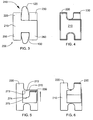
- second fork 230 may be received in a cavity 270 of implant 200 when implant 200 is in a non-use position, and first fork 220 and core 210 may bound opening 240 having substantially an L-shape, prior to the insertion of implant 200 into an interspinous cavity.
- second fork 230 may be extended upwardly (i.e., to an in-use position) such that second fork 230 and first fork 220 bound opening 240 (e.g., having substantially a U-shape) receiving upper spinous process 120.
- Second fork 230 may be held in place via a friction fit between an engaging portion 272 of core 210 and a corresponding engaging portion 274 of second fork 230 when second fork 230 is "snapped into” the remainder of implant 200. Also, an extending portion 275 of fork 230 may abut a bottom side 273 of engagement portion 272 to inhibit vertical movement of fork 230 out of cavity 270.
- second fork 230 may be held in place utilizing a set screw, ratcheting mechanism, shim, spring, or any other means of holding second fork 230 in place and inhibiting separation of second fork 230 from the remainder of implant 200. The use of set screws, ratcheting mechanisms, springs and shims are further discussed below.
- an implant 300 has a first fork 330 separate from, and attachable to, a core 310.
- Implant 300 may include a cavity 305 configured (i.e., shaped and dimensioned) to receive first fork 330.
- First fork 330 may be held in place via a friction fit between walls 312 defining an internal cavity or engaging portion 372 of a core 310 and a corresponding connecting portion 374 of first fork 330 when first fork 330 is "snapped into” the remainder of implant 300.
- Connecting portion 374 and engaging portion 372 may inhibit movement of fork 330 away from core 310.
- first fork 330 and/or core 310 may be sufficiently flexible to allow the insertion of connecting portion 374 into engaging portion 372 such that friction therebetween inhibits separation after they are connected.
- first fork 330 may be held in place utilizing a set screw, ratcheting mechanism, shim, spring, or any other means of holding first fork 330 in place.
- an implant 400 includes a top member 410 movably attached to a bottom member 420.
- a top portion 426 of bottom member 420 is received in a cavity 415 ( FIG. 12 ) of top member 410.
- the cavity is configured (e.g., shaped and dimensioned) to receive bottom member 420.
- cavity 415 is defined by inner surfaces 414 of top member 410 such that the width of bottom member 420 is less than the width of inner surfaces 414 and thus cavity 415 as depicted in FIGS. 12-13 .
- top member 410 and bottom member 420 may be vertically expanded relative to one another such that a minimal amount of top portion 426 of bottom member 420 is received within cavity 415 and implant 400 may be at its maximum height as depicted in FIG. 11 .
- implant 400 may have its height minimized in a non-use position as depicted in FIG. 10 to allow it to be fit into an interspinous space (e.g., space 114) between spinous processes, and implant 400 may then be expanded or increased in height as desired, i.e., to an in-use position.
- Top member 410 may be held in place via a friction fit between an engaging portion, such as inner surfaces 414 of cavity 415, and a corresponding engaging surface, such as outer portion 422, of bottom member 420 when top member 410 and bottom member 420 are extended to a desired height relative to one another.
- top member 410 and bottom member 420 may be held in place relative to each other utilizing a set screw, ratcheting mechanism, shim, spring, or any other means of holding top member 410 and bottom member 420 at a fixed position relative to each other.
- Top member 410 may also include a retaining member 450 configured to retain bottom member 420 connected to top member 410.
- Retaining member 450 may include a connecting member or rod 452 connected to opposite inner surfaces 414 of cavity 415 of top member 410 and may be received in passages 453 of bottom member 420 when bottom member 420 is received in cavity 415.
- Rod 452 may be connected to a holder 455 which is configured (e.g., shaped and dimensioned) to be received in a cavity 425 configured to receive a lower spinous process (e.g., lower spinous process 130).
- Retaining member 450 thus allows movement of bottom member 420 into cavity 415 but inhibits movement of bottom member 420 past retaining member 450 in a direction out of the cavity by contact of holder 455 and rod 452 with upper surfaces 454 of bottom member 420.
- top member 410 and bottom member 420 may be held relative to one another without using retaining member 450 (e.g., via a friction fit, set screw, ratcheting mechanism, shim, spring, or other means of holding top and bottom members relative to each other).
- Top member 410 also includes an opening 416 for receiving an upper spinous process (e.g., upper spinous process 120).
- an implant 500 includes a core 510 having a cavity 515 configured (e.g., shaped and dimensioned) to receive a top member 520 and a bottom member 530 therein when in a non-use position.
- a cavity 515 configured (e.g., shaped and dimensioned) to receive a top member 520 and a bottom member 530 therein when in a non-use position.
- top member 520 and bottom member 530 may be received within cavity 515 to allow implant 500 to be inserted into an interspinous cavity such as interspinous cavity 114 ( FIG. 2 ) while minimizing damage to a supraspinous ligament.
- top member 520 and bottom member 530 may be vertically separated from one another (e.g., using a spring or other biasing mechanism) as depicted in FIGS. 14-15 .
- an upper spinous process e.g., upper spinous process 120 ( FIG. 3 )
- a lower spinous process e.g., lower spinous process 130 ( FIG. 3 )
- cavity 515 is defined by inner surfaces 514 of core 510 such that the widths of top member 520 and bottom member 530 are less than the distance between inner surfaces 514 defining cavity 515.
- top member 520 and bottom member 530 may be vertically expanded relative to one another such that a minimal amount of top portion 535 of bottom member 530 and bottom portion 525 of top member 510 are received within cavity 515 and implant 500 may be at its maximum height as depicted in FIG.S 14-15 .
- implant 500 may have its height minimized in a non-use position as depicted in FIG. 16 to allow it to be easily fit into the interspinous space (e.g., space 114) between the spinous processes and implant 500 may then be expanded or increased in height as desired, i.e., to an in-use position.
- Top member 520 and bottom member 530 may be held in place relative to core 510 in an in-use or a non-use position via a friction fit between an engaging portion, such as outer surfaces 522, of top member 520 and an engaging portion, such as outer surfaces 532, of bottom member 530 with a corresponding engaging portion and/or inner surfaces 514 of core 510.
- top member 520 and bottom member 530 may be held in place relative to each other and core 510 utilizing a set screw, ratcheting mechanism, shim, spring or any other means of holding top member 520 and bottom member 530 relative to core 510 and each other.
- Core 510 may also include a top retaining member 550 configured to retain top member 520 connected to core 510.
- Retaining member 550 may include a connecting member, such as a rod 552, connected to opposite inner surfaces 514 of cavity 515 of core 510 and may be received in passages 553 between upper forks 527 of top member 520 when top member 520 is received in cavity 515.
- Rod 550 may be connected to a holder 555 which is configured (e.g., shaped and dimensioned) to be received in cavity 525 configured to receive an upper spinous process (e.g., upper spinous process 120).
- Retaining member 550 thus allows movement of top member 520 into cavity 515 but inhibits movement of top member 520 past retaining member 550 in a direction out of the cavity by contact of holder 555 and rod 552 with upper surfaces 554 of top member 520.
- a bottom retaining member 580 inhibits movement of bottom member 530 away from cavity 515 by contact between bottom surfaces 585 of bottom member 530 with a holder 595 connected to inner surfaces 514 by a rod (not shown).
- top member 520 and bottom member 530 may be held in place relative to core 510 in an in-use, or non-use position without utilizing top retaining member 550 or bottom retaining member 580 (e.g., via a friction fit, set screw, ratcheting mechanism, shim, spring, or other means of holding top and bottom members relative to each other).
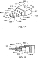
- an implant 600 includes a plurality of telescoping sections 610.
- a first section 620 has a cavity 625 which may at least partially receive a second section 630 therein.
- a third section 640 may be at least partially received in a cavity 635 of second section 630.
- a fourth section 650 may be received at least partially in a cavity 645 of third section 640.
- Each section may be received in the appropriate cavity of the section connected thereto when in a non-use position, i.e. prior to insertion of implant 600 into an interspinous cavity such as interspinous cavity 114 ( FIG. 2 ). Adjacent sections may then be held relative to one another in an in-use position, as depicted in FIGS.
- fourth section 650 may include a cavity 655 for receiving a spinous process, which is bounded by forks 657
- first section 620 may include a cavity 625 for receiving an opposite spinous process, which is bounded by forks 627.
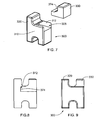
- an implant 700 may include a fork 720 rotatably attached to a core 710.
- Fork 720 may be movable (e.g., rotatable about a pin 722) from a first (i.e., non-use) position in which the implant includes an h-shape, as depicted in FIGS. 19 and 20 to a second (i.e., in-use) position depicted in FIG. 21 in which the implant is H-shaped.
- An internal end 723 of fork 720 may be received in a cavity 712 of core 710 and cavity 712 may be formed in an arc shape to allow such rotation as depicted in FIG. 20 .
- Fork 720 may have a rectilinear cross-section as depicted in the figures, for example.
- Fork 720 may be located in a non-use position in the first position which may facilitate the insertion of the implant into an interspinous space such as interspinous space 114 ( FIG. 2 ).
- the offset position of fork 720 in FIGS. 19-20 may allow the implant to be manipulated under or around the supraspinous ligament to avoid (or minimize) the necessity of cutting such ligament.
- fork 720 and a second fork 730 may be substantially parallel to each other and may bound an opening 725 for receiving an upper spinous process such as upper spinous process 120 ( FIG. 2 ).
- Core 710, second fork 730, a third fork 740, and a fourth fork 750 may be formed integral (i.e., monolithic) to one another and may be substantially rigid and non-movable relative to each other.
- First fork 720 may be held in an in-use position ( FIG. 21 ) and/or a non-use position ( FIG. 20 ) via a friction fit between outer surface 724 of fork 720 and an inner surface 713 of core 710.
- first fork 720 may be held in place relative to core 710 utilizing a set screw, shim, ratcheting, spring, or any means for maintaining the fork as depicted in FIG. 21 , e.g., parallel to the other forks and bounding opening 725.
- first fork 720 may be connected to core 710 via a pin or any other means for allowing the movability thereof relative to core 710.
- an implant 1700 includes a fork 1720 hingedly or otherwise rotatably connected to a core 1710 about a hinge 1722.
- Core 1710 may include an upper fork 1730 and a lower fork 1740 along with a right lower fork 1750.
- Upper fork 1730 and fork 1720 may bound an opening 1725 for receiving an upper spinous process, such as upper spinous process 120 ( FIG. 2 ).
- Lower fork 1740 and right lower fork 1750 may bound a cavity 1726 for receiving a lower spinous process, such as lower spinous process 130 ( FIG. 2 ).
- FIG. 21A an implant 1700 includes a fork 1720 hingedly or otherwise rotatably connected to a core 1710 about a hinge 1722.
- Core 1710 may include an upper fork 1730 and a lower fork 1740 along with a right lower fork 1750.
- Upper fork 1730 and fork 1720 may bound an opening 1725 for receiving an upper spinous process, such as upper spinous process 120 (
- fork 1720 is in a non-use position while the rotation of fork 1720 in a counter-clockwise direction such that fork 1720 is substantially parallel to fork 1730 results in fork 1720 being located in an in-use position.
- fork 1720 may be held in the in-use positions via a set screw, ratcheting mechanism, shim, spring, or any other means of holding fork 1720 relative to core 1710.
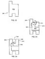
- an implant 800 may include a first fork 820 which is rotatable relative to a core 810.
- First fork 820 may have an L-shape and may be entirely received in a cavity 815 of core 810 when in a non-use position ( FIGS. 22-23 ).
- the position of first fork 820 entirely within the cavity may allow the implant to be manipulated under or around the supraspinous ligament to avoid the necessity of cutting such ligament during the insertion thereof into an interspinous cavity, such as interspinous cavity 114.
- fork 820 may be rotated about a pin 822 such that an extending portion 821 of fork 820 extending outside cavity 815 is substantially parallel to a second fork 830 and the forks bound an opening 825 configured (e.g., shaped and dimensioned) to receive an upper spinous process such as upper spinous process 120 ( FIG. 2 ).
- Core 810 may be received in an interspinous space such as interspinous space 114 ( FIG. 2 ).
- First fork 820 may be held in place relative to core 810 via a friction fit between outer surface 824 of fork 820 and an inner surface 813 of core 810.
- first fork 820 may be held in place relative to core 810 utilizing a set screw, ratcheting mechanism, shim, spring, or any other means of holding first fork 820 relative to core 810.
- an implant 900 includes a top member 910 pivotally connected to a bottom member 920 at a hinge, pivot or pin 925.
- a bottom side 912 of top member 910 may abut a topside 922 of bottom member 920.
- a cavity 915 may be present between bottom side 912 of top member 910 and topside 922 of bottom member 920.
- a minimal left side height 923 which may be less than minimum height 926 as depicted, may further facilitate the insertion desired.
- fork top member 910 and bottom member 920 may be rotated about pin 925 relative to each other from such minimum height to the maximum height.
- Top member 910 and bottom member 920 may be held relative to one another in the in-use position as depicted in FIG. 26 by a shim, set screw, ratcheting mechanism, spring, or any other means of holding the members relative to one another such that they may maintain an upper spinous process (e.g. upper spinous process 120 ( FIG. 3 )) and a lower spinous process (e.g., lower spinous process 130( FIG. 3 )) at a desired position relative to one another.
- top member 910 may include a cavity 913 for receiving a spinous process, such as upper spinous process 120 ( FIG. 3 )
- bottom member 930 may include a cavity 933 for receiving an opposite spinous process, such as lower spinous process 130 ( FIG. 3 ).
- implant 200 may include a threaded boss 201 aligned in a width direction of the implant for receiving a set screw 202 to hold second fork 230 in position.
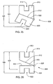
- FIG. 28 depicts a side cross-sectional view of a non-use position also depicted in FIG. 5
- FIG. 29 depicts a side view of an in-use position as also depicted in FIG. 4 .
- Set screw 202 may be threaded into boss 201 to maintain second fork 230 in such non-use or in-use position.
- a bore 203 configured (e.g., shaped and dimensioned) to receive the set screw may be aligned in a direction transverse to a height of implant 200 and in a lengthwise direction relative to the implant.
- Such a set screw may hold second fork 230 in a non-use in FIG. 30 and an in-use position in FIG. 31 .
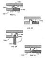
- FIGS. 32-33 depict an H-shaped implant 1300 similar to implant 200 ( FIGS. 4-6 ) having a fork 1310 which is receivable in a cavity 1315.
- a ratchet mechanism 1320 is received in the cavity and is engageable with teeth 1317 on a side 1319 of fork 1310 such that ratchet 1320 engages with teeth 1317 to maintain fork 1310 in a particular position by inhibiting backward movement toward a core 1322 of implant 1300.
- FIG. 32 depicts a non-use position and FIG. 33 depicts an in-use position.
- FIGS. 34-35 depict a ratchet utilized with an implant 1340 which is similar to implant 700 depicted in FIGS. 19-21 .
- a ratchet 1350 engages teeth 1355 of a fork 1342. As fork 1342 is rotated from a non-use position depicted in FIG. 34 to an in-use position depicted in FIG. 35 , ratchet 1350 moves along teeth 1355 and retains fork 1342 in a particular position (i.e. by inhibiting backward rotation) according to the rotation of fork 1342 from the non-use position to the in-use position.
- FIGS. 36-37 depict the use of a shim with the embodiments similar or identical to those depicted in FIGS. 4-6 , 10-16 , and 22-24 .
- a shim 1370 may be received in an implant 1400 similar to implant 200 ( FIGS. 4-6 ) except for an opening 1414 on a front side thereof to allow insertion of shim 1370 to maintain fork 1330, which is similar to fork 230, in an in-use position as depicted in FIG. 36 .
- implant 800 also depicted in FIGS.
- FIG. 21-23 may receive a shim 1450 in cavity 815 in the in-use position to maintain fork 820 elevated such that fork 820 bounds cavity 825 configured to receive an upper spinous process, such as upper spinous process 120.
- FIG. 38 depicts implant 1500, which is similar to implant 400 depicted in FIG.S 10-12 except for an opening 1514 in a front side thereof to allow shim 1550 to be received in a cavity 1515. Shim 1550 may hold upper member 1510 in an in-use position as depicted in FIG. 38 similar to implant 400 depicted in FIG. 10 .
- FIG. 39 depicts implant 1600 receiving a shim 1650 through an opening 1614 in a cavity 1615.
- Implant 1600 is similar to implant 500 except for opening 1614 in a front side of implant 1600 to allow the shim to be inserted therein.
- shim 1650 may maintain top member 1620 and bottom member 1630 separated from one another such that an upper spinous process may be received in cavity 1625 and a lower spinous process may be received in cavity 1635 of top member 1620 and bottom member 1630.
- the embodiments depicted include openings for receiving shims, which are located in particular positions, the openings could be located in various positions on the implant, such as a top, bottom or the side(s) thereof.
- the forks and top and bottom members described above, which are movable between in-use and non-positions may be maintained in such in-use and/or non-use positions utilizing a spring or other biasing mechanism which may bias the implant in the in-use or non-use position.
- a spring or other biasing mechanism which may bias the implant in the in-use or non-use position.
- the shims depicted in FIGS. 37-39 could be replaced by a spring which biases the forks toward an in-use position configured to bound upper and lower spinous processes.
- a biasing mechanism such as a spring
- a set screw or other means may be utilized to hold the implant in the non-use position prior to its insertion into the interspinous space.
- the implants described could be formed of various materials which are biocompatible and which may maintain the spinous processes relative to one another in desired positions.
- the described implants and portions thereof may be formed of rigid materials (e.g., metal, such as titanium, or stiff polymers), semi rigid materials (e.g. PEEK, a less stiff plastic or silicone), or a substantially flexible material (e.g., silicone or flexible plastic).
- the implant described herein could have a modulus of elasticity substantially equal to a modulus of elasticity of bone, particularly the bone forming the spinous processes which the implants support.
- the implants could be loaded and manipulated from a non-use position to an in-use position from one side of the interspinous space (e.g., from a side of a mid-line of a spine of a patient).
- a portion of an implant could be inserted from one side of a mid-line of the spine (e.g., one side of the interspinous space) while a second portion of the implant could be inserted from the other side thereof.
Landscapes
- Health & Medical Sciences (AREA)
- Orthopedic Medicine & Surgery (AREA)
- Life Sciences & Earth Sciences (AREA)
- Neurology (AREA)
- Surgery (AREA)
- Heart & Thoracic Surgery (AREA)
- Engineering & Computer Science (AREA)
- Biomedical Technology (AREA)
- Nuclear Medicine, Radiotherapy & Molecular Imaging (AREA)
- Medical Informatics (AREA)
- Molecular Biology (AREA)
- Animal Behavior & Ethology (AREA)
- General Health & Medical Sciences (AREA)
- Public Health (AREA)
- Veterinary Medicine (AREA)
- Prostheses (AREA)
Claims (4)
- Ein System (900) zum Beabstanden von Wirbeln, das System umfassend:ein erstes Teil (910), das eine erste Längsachse definiert, ein zweites Teil (920), das eine zweite Längsachse definiert und ein Gelenk (925), das eine Gelenkachse definiert, wobei die Gelenkachse versetzt zur ersten Längsachse und zur zweiten Längsachse ist und das erste Teil mit dem zweiten Teil drehbar verbindet, so dass das erste Teil und das zweite Teil relativ zueinander um die Gelenkachse aus einer Nicht-In-Gebrauchs-Position in eine In-Gebrauchs-Position drehbar sind,wobei das erste Teil (910) eine erste Gabel und eine zweite Gabel umfasst, wobei die erste und die zweite Gabel Formen haben, so dass sie sich entlang von vertikalen Seiten eines ersten Wirbelfortsatzes erstrecken und zwischen sich eine erste Aussparung (913) bestimmen, in der der erste Wirbelfortsatz in der In-Gebrauchs-Position aufnehmbar ist,wobei das zweite Teil (920) eine dritte Gabel und eine vierte Gabel umfasst, wobei die dritte und die vierte Gabel Formen haben, so dass sie sich entlang von vertikalen Seiten eines zweiten Wirbelfortsatzes der direkt neben dem ersten Wirbelfortsatz liegt erstrecken und zwischen sich eine zweite Aussparung (933) bestimmen, in der der zweite Wirbelfortsatz in der In-Gebrauchs-Position aufnehmbar ist; undwobei die erste Gabel relativ zur zweiten Gabel nicht bewegbar ist und die Gelenksachse relativ zu dem ersten und zweiten Teil so ausgerichtet ist, dass wenn der erste und der zweite Wirbelfortsatz in der ersten bzw. zweiten Aussparung in der In-Gebrauchs-Position aufgenommen sind, die Gelenkdachse im Wesentlichen parallel zu einer Sagittalebene liegt, die durch die aufgenommenen ersten und zweiten Wirbelfortsätze bestimmt wird.
- Das System nach Anspruch 1, wobei die dritte Gabel relativ zur vierten Gabel nicht bewegbar ist.
- Das System nach Anspruch 1 oder Anspruch 2, wobei von der ersten und zweiten Gabel die erste Gabel weiter entfernt von dem Gelenk (925) ist und von der dritten und vierten Gabel die dritte Gabel weiter entfernt von dem Gelenk ist und der Abstand zwischen der ersten und der dritten Gabel so ausgebildet ist, das er sich vergrößert, wenn das erste und zweite Teil (910, 920) relativ zueinander um das Gelenk aus der Nicht-In-Gebrauchs-Position in die In-Gebrauchs-Position gedreht werden.
- Das System nach Anspruch 3, wobei das erste Teil (910) eine erste Oberfläche (912) und das zweite Teil (920) eine zweite Oberfläche (922) umfasst, wobei die erste und die zweite Oberfläche so angeordnet sind, dass sie in der Nicht-In-Gebrauch-Position berühren aneinander angrenzen und in der In-Gebrauch-Position zwischen sich eine Aussparung (915) bilden.
Applications Claiming Priority (2)
| Application Number | Priority Date | Filing Date | Title |
|---|---|---|---|
| US11/560,169 US7879104B2 (en) | 2006-11-15 | 2006-11-15 | Spinal implant system |
| PCT/US2007/082961 WO2008060851A1 (en) | 2006-11-15 | 2007-10-30 | Spinal implant system |
Publications (2)
| Publication Number | Publication Date |
|---|---|
| EP2091448A1 EP2091448A1 (de) | 2009-08-26 |
| EP2091448B1 true EP2091448B1 (de) | 2011-08-03 |
Family
ID=39092327
Family Applications (1)
| Application Number | Title | Priority Date | Filing Date |
|---|---|---|---|
| EP07844722A Not-in-force EP2091448B1 (de) | 2006-11-15 | 2007-10-30 | Wirbelsäulenimplantatsystem |
Country Status (6)
| Country | Link |
|---|---|
| US (1) | US7879104B2 (de) |
| EP (1) | EP2091448B1 (de) |
| AT (1) | ATE518491T1 (de) |
| AU (1) | AU2007319554A1 (de) |
| ES (1) | ES2366590T3 (de) |
| WO (1) | WO2008060851A1 (de) |
Families Citing this family (123)
| Publication number | Priority date | Publication date | Assignee | Title |
|---|---|---|---|---|
| US20080215058A1 (en) * | 1997-01-02 | 2008-09-04 | Zucherman James F | Spine distraction implant and method |
| US7201751B2 (en) * | 1997-01-02 | 2007-04-10 | St. Francis Medical Technologies, Inc. | Supplemental spine fixation device |
| US6068630A (en) * | 1997-01-02 | 2000-05-30 | St. Francis Medical Technologies, Inc. | Spine distraction implant |
| US20080086212A1 (en) | 1997-01-02 | 2008-04-10 | St. Francis Medical Technologies, Inc. | Spine distraction implant |
| US20050245937A1 (en) * | 2004-04-28 | 2005-11-03 | St. Francis Medical Technologies, Inc. | System and method for insertion of an interspinous process implant that is rotatable in order to retain the implant relative to the spinous processes |
| US7959652B2 (en) * | 2005-04-18 | 2011-06-14 | Kyphon Sarl | Interspinous process implant having deployable wings and method of implantation |
| US20080021468A1 (en) * | 2002-10-29 | 2008-01-24 | Zucherman James F | Interspinous process implants and methods of use |
| US7749252B2 (en) | 2005-03-21 | 2010-07-06 | Kyphon Sarl | Interspinous process implant having deployable wing and method of implantation |
| US7549999B2 (en) | 2003-05-22 | 2009-06-23 | Kyphon Sarl | Interspinous process distraction implant and method of implantation |
| US7909853B2 (en) * | 2004-09-23 | 2011-03-22 | Kyphon Sarl | Interspinous process implant including a binder and method of implantation |
| US8048117B2 (en) | 2003-05-22 | 2011-11-01 | Kyphon Sarl | Interspinous process implant and method of implantation |
| US8147548B2 (en) * | 2005-03-21 | 2012-04-03 | Kyphon Sarl | Interspinous process implant having a thread-shaped wing and method of implantation |
| US8070778B2 (en) | 2003-05-22 | 2011-12-06 | Kyphon Sarl | Interspinous process implant with slide-in distraction piece and method of implantation |
| US7335203B2 (en) * | 2003-02-12 | 2008-02-26 | Kyphon Inc. | System and method for immobilizing adjacent spinous processes |
| FR2871366A1 (fr) | 2004-06-09 | 2005-12-16 | Ceravic Soc Par Actions Simpli | Implant expansible prothetique osseux |
| US8241330B2 (en) | 2007-01-11 | 2012-08-14 | Lanx, Inc. | Spinous process implants and associated methods |
| US9055981B2 (en) | 2004-10-25 | 2015-06-16 | Lanx, Inc. | Spinal implants and methods |
| US8100943B2 (en) * | 2005-02-17 | 2012-01-24 | Kyphon Sarl | Percutaneous spinal implants and methods |
| US20070276493A1 (en) | 2005-02-17 | 2007-11-29 | Malandain Hugues F | Percutaneous spinal implants and methods |
| US8157841B2 (en) | 2005-02-17 | 2012-04-17 | Kyphon Sarl | Percutaneous spinal implants and methods |
| US8043335B2 (en) | 2005-02-17 | 2011-10-25 | Kyphon Sarl | Percutaneous spinal implants and methods |
| US8097018B2 (en) | 2005-02-17 | 2012-01-17 | Kyphon Sarl | Percutaneous spinal implants and methods |
| US8057513B2 (en) | 2005-02-17 | 2011-11-15 | Kyphon Sarl | Percutaneous spinal implants and methods |
| US7988709B2 (en) | 2005-02-17 | 2011-08-02 | Kyphon Sarl | Percutaneous spinal implants and methods |
| US7993342B2 (en) * | 2005-02-17 | 2011-08-09 | Kyphon Sarl | Percutaneous spinal implants and methods |
| US8007521B2 (en) | 2005-02-17 | 2011-08-30 | Kyphon Sarl | Percutaneous spinal implants and methods |
| US8034080B2 (en) | 2005-02-17 | 2011-10-11 | Kyphon Sarl | Percutaneous spinal implants and methods |
| US7927354B2 (en) * | 2005-02-17 | 2011-04-19 | Kyphon Sarl | Percutaneous spinal implants and methods |
| US8096994B2 (en) | 2005-02-17 | 2012-01-17 | Kyphon Sarl | Percutaneous spinal implants and methods |
| US8096995B2 (en) * | 2005-02-17 | 2012-01-17 | Kyphon Sarl | Percutaneous spinal implants and methods |
| US7998174B2 (en) * | 2005-02-17 | 2011-08-16 | Kyphon Sarl | Percutaneous spinal implants and methods |
| US8029567B2 (en) | 2005-02-17 | 2011-10-04 | Kyphon Sarl | Percutaneous spinal implants and methods |
| US8038698B2 (en) | 2005-02-17 | 2011-10-18 | Kphon Sarl | Percutaneous spinal implants and methods |
| US9034041B2 (en) | 2005-03-31 | 2015-05-19 | Life Spine, Inc. | Expandable spinal interbody and intravertebral body devices |
| US8940048B2 (en) | 2005-03-31 | 2015-01-27 | Life Spine, Inc. | Expandable spinal interbody and intravertebral body devices |
| US9801733B2 (en) | 2005-03-31 | 2017-10-31 | Life Spine, Inc. | Expandable spinal interbody and intravertebral body devices |
| US8066742B2 (en) * | 2005-03-31 | 2011-11-29 | Warsaw Orthopedic, Inc. | Intervertebral prosthetic device for spinal stabilization and method of implanting same |
| US8034079B2 (en) | 2005-04-12 | 2011-10-11 | Warsaw Orthopedic, Inc. | Implants and methods for posterior dynamic stabilization of a spinal motion segment |
| US7727233B2 (en) | 2005-04-29 | 2010-06-01 | Warsaw Orthopedic, Inc. | Spinous process stabilization devices and methods |
| US7862591B2 (en) | 2005-11-10 | 2011-01-04 | Warsaw Orthopedic, Inc. | Intervertebral prosthetic device for spinal stabilization and method of implanting same |
| US20070173823A1 (en) * | 2006-01-18 | 2007-07-26 | Sdgi Holdings, Inc. | Intervertebral prosthetic device for spinal stabilization and method of implanting same |
| US8083795B2 (en) | 2006-01-18 | 2011-12-27 | Warsaw Orthopedic, Inc. | Intervertebral prosthetic device for spinal stabilization and method of manufacturing same |
| US7837711B2 (en) * | 2006-01-27 | 2010-11-23 | Warsaw Orthopedic, Inc. | Artificial spinous process for the sacrum and methods of use |
| US8262698B2 (en) | 2006-03-16 | 2012-09-11 | Warsaw Orthopedic, Inc. | Expandable device for insertion between anatomical structures and a procedure utilizing same |
| US8118844B2 (en) | 2006-04-24 | 2012-02-21 | Warsaw Orthopedic, Inc. | Expandable device for insertion between anatomical structures and a procedure utilizing same |
| US8252031B2 (en) | 2006-04-28 | 2012-08-28 | Warsaw Orthopedic, Inc. | Molding device for an expandable interspinous process implant |
| US8048118B2 (en) | 2006-04-28 | 2011-11-01 | Warsaw Orthopedic, Inc. | Adjustable interspinous process brace |
| US20070270823A1 (en) * | 2006-04-28 | 2007-11-22 | Sdgi Holdings, Inc. | Multi-chamber expandable interspinous process brace |
| US8105357B2 (en) | 2006-04-28 | 2012-01-31 | Warsaw Orthopedic, Inc. | Interspinous process brace |
| US8048119B2 (en) | 2006-07-20 | 2011-11-01 | Warsaw Orthopedic, Inc. | Apparatus for insertion between anatomical structures and a procedure utilizing same |
| US20080086115A1 (en) | 2006-09-07 | 2008-04-10 | Warsaw Orthopedic, Inc. | Intercostal spacer device and method for use in correcting a spinal deformity |
| FR2907329B1 (fr) * | 2006-10-20 | 2009-02-27 | Jean Taylor | Prothese vertebrale interepineuse |
| US8097019B2 (en) | 2006-10-24 | 2012-01-17 | Kyphon Sarl | Systems and methods for in situ assembly of an interspinous process distraction implant |
| FR2908035B1 (fr) | 2006-11-08 | 2009-05-01 | Jean Taylor | Implant interepineux |
| US7879104B2 (en) | 2006-11-15 | 2011-02-01 | Warsaw Orthopedic, Inc. | Spinal implant system |
| US7955392B2 (en) * | 2006-12-14 | 2011-06-07 | Warsaw Orthopedic, Inc. | Interspinous process devices and methods |
| US9265532B2 (en) | 2007-01-11 | 2016-02-23 | Lanx, Inc. | Interspinous implants and methods |
| CN101677862B (zh) | 2007-02-06 | 2012-04-18 | 先锋外科技术公司 | 椎间植入装置及其插入方法 |
| US7842074B2 (en) | 2007-02-26 | 2010-11-30 | Abdou M Samy | Spinal stabilization systems and methods of use |
| US8231656B2 (en) | 2007-04-10 | 2012-07-31 | Life Spine, Inc. | Adjustable spine distraction implant |
| US8840646B2 (en) * | 2007-05-10 | 2014-09-23 | Warsaw Orthopedic, Inc. | Spinous process implants and methods |
| US20080294200A1 (en) * | 2007-05-25 | 2008-11-27 | Andrew Kohm | Spinous process implants and methods of using the same |
| US8105358B2 (en) | 2008-02-04 | 2012-01-31 | Kyphon Sarl | Medical implants and methods |
| TW200938157A (en) * | 2008-03-11 | 2009-09-16 | Fong-Ying Chuang | Interspinous spine fixing device |
| US8114136B2 (en) | 2008-03-18 | 2012-02-14 | Warsaw Orthopedic, Inc. | Implants and methods for inter-spinous process dynamic stabilization of a spinal motion segment |
| WO2009125242A1 (en) * | 2008-04-08 | 2009-10-15 | Vexim | Apparatus for restoration of the spine and methods of use thereof |
| US9301788B2 (en) | 2008-04-10 | 2016-04-05 | Life Spine, Inc. | Adjustable spine distraction implant |
| US20100106252A1 (en) * | 2008-10-29 | 2010-04-29 | Kohm Andrew C | Spinal implants having multiple movable members |
| US8114131B2 (en) | 2008-11-05 | 2012-02-14 | Kyphon Sarl | Extension limiting devices and methods of use for the spine |
| US8246655B2 (en) * | 2009-01-09 | 2012-08-21 | Pioneer Surgical Technology, Inc. | Intervertebral implant devices and methods for insertion thereof |
| US8114135B2 (en) * | 2009-01-16 | 2012-02-14 | Kyphon Sarl | Adjustable surgical cables and methods for treating spinal stenosis |
| US10052139B2 (en) | 2009-01-26 | 2018-08-21 | Life Spine, Inc. | Flexible and static interspinous/inter-laminar spinal spacers |
| US8236031B2 (en) | 2009-01-26 | 2012-08-07 | Life Spine, Inc. | Flexible and static interspinous/inter-laminar spinal spacers |
| BRPI0924440B8 (pt) | 2009-03-12 | 2021-06-22 | Vexim | implante expansível vertebral |
| MX2011010375A (es) | 2009-03-31 | 2012-02-23 | Lanx Inc | Implantes de apofisis espinosa y metodos asociados. |
| US8372117B2 (en) | 2009-06-05 | 2013-02-12 | Kyphon Sarl | Multi-level interspinous implants and methods of use |
| US8157842B2 (en) | 2009-06-12 | 2012-04-17 | Kyphon Sarl | Interspinous implant and methods of use |
| US8771317B2 (en) * | 2009-10-28 | 2014-07-08 | Warsaw Orthopedic, Inc. | Interspinous process implant and method of implantation |
| US8114132B2 (en) | 2010-01-13 | 2012-02-14 | Kyphon Sarl | Dynamic interspinous process device |
| US8317831B2 (en) | 2010-01-13 | 2012-11-27 | Kyphon Sarl | Interspinous process spacer diagnostic balloon catheter and methods of use |
| US8147526B2 (en) | 2010-02-26 | 2012-04-03 | Kyphon Sarl | Interspinous process spacer diagnostic parallel balloon catheter and methods of use |
| US8814908B2 (en) | 2010-07-26 | 2014-08-26 | Warsaw Orthopedic, Inc. | Injectable flexible interspinous process device system |
| JP5859009B2 (ja) * | 2010-09-23 | 2016-02-10 | アルファテック スパイン, インコーポレイテッド | クランプ棘間スペーサ装置及び使用方法 |
| US8721687B2 (en) | 2010-11-29 | 2014-05-13 | Life Spine, Inc. | Spinal implant for lumbar vertebra to sacrum fixation |
| US8636771B2 (en) | 2010-11-29 | 2014-01-28 | Life Spine, Inc. | Spinal implants for lumbar vertebra to sacrum fixation |
| US8496689B2 (en) | 2011-02-23 | 2013-07-30 | Farzad Massoudi | Spinal implant device with fusion cage and fixation plates and method of implanting |
| US8562650B2 (en) | 2011-03-01 | 2013-10-22 | Warsaw Orthopedic, Inc. | Percutaneous spinous process fusion plate assembly and method |
| US8425560B2 (en) | 2011-03-09 | 2013-04-23 | Farzad Massoudi | Spinal implant device with fixation plates and lag screws and method of implanting |
| US8591548B2 (en) | 2011-03-31 | 2013-11-26 | Warsaw Orthopedic, Inc. | Spinous process fusion plate assembly |
| CN103841909B (zh) | 2011-04-07 | 2017-02-15 | 维克辛姆公司 | 可张开矫形设备 |
| US8591549B2 (en) | 2011-04-08 | 2013-11-26 | Warsaw Orthopedic, Inc. | Variable durometer lumbar-sacral implant |
| ITVI20110156A1 (it) * | 2011-06-17 | 2012-12-18 | Alexandre Alvise | Spaziatore percutaneo interspinoso a bassa invasivita' e strumentario per la sua implantazione |
| US20120323276A1 (en) | 2011-06-17 | 2012-12-20 | Bryan Okamoto | Expandable interspinous device |
| US9149306B2 (en) | 2011-06-21 | 2015-10-06 | Seaspine, Inc. | Spinous process device |
| FR2977139B1 (fr) * | 2011-06-30 | 2014-08-22 | Ldr Medical | Implant inter-epineux et instrument d’implantation |
| US10555821B2 (en) * | 2011-09-21 | 2020-02-11 | Tov Inge Vestgaarden | Method and apparatus for spinal interbody fusion including fixation or locking plate |
| US20160106549A1 (en) | 2011-09-21 | 2016-04-21 | Vg Innovations, Llc | Interconnected Locking Plates for Adjacent Spinal Vertebral Bodies |
| US11812923B2 (en) | 2011-10-07 | 2023-11-14 | Alan Villavicencio | Spinal fixation device |
| US10383741B2 (en) | 2013-03-13 | 2019-08-20 | Life Spine, Inc. | Expandable spinal interbody assembly |
| US12193948B2 (en) | 2013-03-13 | 2025-01-14 | Life Spine, Inc. | Expandable implant assembly |
| US10426632B2 (en) | 2013-03-13 | 2019-10-01 | Life Spine, Inc. | Expandable spinal interbody assembly |
| US11304818B2 (en) | 2013-03-13 | 2022-04-19 | Life Spine, Inc. | Expandable spinal interbody assembly |
| US10154911B2 (en) | 2013-03-13 | 2018-12-18 | Life Spine, Inc. | Expandable implant assembly |
| US9668773B2 (en) * | 2013-03-14 | 2017-06-06 | Globus Medical, Inc. | Spinal implant for use in thoracic insufficiency syndrome |
| FR3015221B1 (fr) | 2013-12-23 | 2017-09-01 | Vexim | Systeme d'implant intravertebral expansible avec fixation pediculaire posterieure |
| US10022246B2 (en) | 2014-12-16 | 2018-07-17 | Donald Mackenzie | Interlaminar fixation device |
| US10729554B2 (en) * | 2015-10-09 | 2020-08-04 | DePuy Synthes Products, Inc. | Expandable trials |
| US10335207B2 (en) | 2015-12-29 | 2019-07-02 | Nuvasive, Inc. | Spinous process plate fixation assembly |
| FR3048176A1 (fr) | 2016-02-26 | 2017-09-01 | Ldr Medical | Systeme d'implants d'arthrodese rachidienne |
| US11896494B2 (en) | 2017-07-10 | 2024-02-13 | Life Spine, Inc. | Expandable implant assembly |
| US11033403B2 (en) | 2017-07-10 | 2021-06-15 | Life Spine, Inc. | Expandable implant assembly |
| JP7521152B2 (ja) | 2017-09-08 | 2024-07-24 | エクスタント メディカル ホールディングス,インコーポレイテッド. | 椎間インプラント、器具、及び方法 |
| USD907771S1 (en) | 2017-10-09 | 2021-01-12 | Pioneer Surgical Technology, Inc. | Intervertebral implant |
| EP3979951A1 (de) | 2019-06-10 | 2022-04-13 | Life Spine, Inc. | Expandierbare implantatanordnung mit kompressionsmerkmalen |
| US12042395B2 (en) | 2019-06-11 | 2024-07-23 | Life Spine, Inc. | Expandable implant assembly |
| US11857432B2 (en) | 2020-04-13 | 2024-01-02 | Life Spine, Inc. | Expandable implant assembly |
| US11602439B2 (en) | 2020-04-16 | 2023-03-14 | Life Spine, Inc. | Expandable implant assembly |
| FR3110074A1 (fr) * | 2020-05-14 | 2021-11-19 | Cousin Biotech | Dispositif implantable, notamment de type espaceur intervertébral |
| US12336917B2 (en) | 2020-05-15 | 2025-06-24 | Life Spine, Inc. | Steerable implant assembly |
| US11723778B1 (en) | 2021-09-23 | 2023-08-15 | Nofusco Corporation | Vertebral implant system and methods of use |
| US11602440B2 (en) | 2020-06-25 | 2023-03-14 | Life Spine, Inc. | Expandable implant assembly |
| US11554020B2 (en) | 2020-09-08 | 2023-01-17 | Life Spine, Inc. | Expandable implant with pivoting control assembly |
| US11896268B2 (en) * | 2022-01-24 | 2024-02-13 | Linares Spinal Devices, Llc | Expandable spinal rack gear jack for installation between upper and lower succeeding superior articular processes |
Family Cites Families (337)
| Publication number | Priority date | Publication date | Assignee | Title |
|---|---|---|---|---|
| US624969A (en) * | 1899-05-16 | Peter peterson | ||
| US1153797A (en) | 1915-04-29 | 1915-09-14 | Jules Emile Kegreisz | Expansion-anchor. |
| US1616347A (en) | 1925-07-06 | 1927-02-01 | Lox Seal Corp | Pile-wire cutter |
| US1870942A (en) | 1928-05-26 | 1932-08-09 | Gynex Corp | Syringe |
| US2077804A (en) * | 1936-05-19 | 1937-04-20 | Morrison Gordon Monroe | Device for treating fractures of the neck of the femur |
| US2299308A (en) | 1941-08-15 | 1942-10-20 | Russell A Creighton | Self-locking spike |
| US2686877A (en) | 1946-03-27 | 1954-08-17 | Us Navy | Automatic frequency control system |
| US2485531A (en) | 1948-01-13 | 1949-10-18 | Dzus William | Surgical toggle bolt |
| US2607370A (en) | 1948-07-13 | 1952-08-19 | Oscar F Anderson | Pipe plug |
| US2677369A (en) * | 1952-03-26 | 1954-05-04 | Fred L Knowles | Apparatus for treatment of the spinal column |
| US3065659A (en) | 1959-09-28 | 1962-11-27 | Superior Concrete Accessories | Expansion bolt |
| US3108595A (en) | 1960-08-08 | 1963-10-29 | Alfred P Overment | Retention catheter |
| US3426364A (en) * | 1966-08-25 | 1969-02-11 | Colorado State Univ Research F | Prosthetic appliance for replacing one or more natural vertebrae |
| US3648691A (en) * | 1970-02-24 | 1972-03-14 | Univ Colorado State Res Found | Method of applying vertebral appliance |
| DE2112139B2 (de) | 1971-03-13 | 1973-02-01 | Fischer, Artur, 7241 Tumhngen | Huelsenfoermiges verbindungselement fuer die kompressions-osteosynthese bei roehrenknochenfrakturen |
| US4011602A (en) * | 1975-10-06 | 1977-03-15 | Battelle Memorial Institute | Porous expandable device for attachment to bone tissue |
| US4704057A (en) | 1976-09-15 | 1987-11-03 | Mechanical Plastics Corp. | Fastening element |
| PL114098B1 (en) * | 1978-04-14 | 1981-01-31 | Wyzsza Szkola Inzynierska | Apparatus for correcting spinal curvature |
| US4274324A (en) | 1978-04-18 | 1981-06-23 | Giannuzzi Louis | Hollow wall screw anchor |
| CH628803A5 (en) | 1978-05-12 | 1982-03-31 | Sulzer Ag | Implant insertable between adjacent vertebrae |
| US4237875A (en) | 1979-02-23 | 1980-12-09 | Towmotor Corporation | Dynamic intramedullary compression nailing |
| US4289123A (en) | 1980-03-31 | 1981-09-15 | Dunn Harold K | Orthopedic appliance |
| GB2083754B (en) | 1980-09-15 | 1984-04-26 | Rezaian Seyed Mahmoud | Spinal fixator |
| SU988281A1 (ru) | 1981-06-26 | 1983-01-15 | За витель | Устройство дл фиксации позвоночника |
| US4646998A (en) * | 1981-11-20 | 1987-03-03 | Clairson International Corporation | Wall-mounted shelf support clip |
| US4519100A (en) * | 1982-09-30 | 1985-05-28 | Orthopedic Equipment Co. Inc. | Distal locking intramedullary nail |
| US4822226A (en) * | 1983-08-08 | 1989-04-18 | Kennedy Arvest G | Wing nut retainer and extractor |
| US4554914A (en) | 1983-10-04 | 1985-11-26 | Kapp John P | Prosthetic vertebral body |
| US4553273A (en) | 1983-11-23 | 1985-11-19 | Henry Ford Hospital | Vertebral body prosthesis and spine stabilizing method |
| GB8333442D0 (en) | 1983-12-15 | 1984-01-25 | Showell A W Sugicraft Ltd | Devices for spinal fixation |
| US4611582A (en) | 1983-12-27 | 1986-09-16 | Wisconsin Alumni Research Foundation | Vertebral clamp |
| US4604995A (en) | 1984-03-30 | 1986-08-12 | Stephens David C | Spinal stabilizer |
| US4573454A (en) * | 1984-05-17 | 1986-03-04 | Hoffman Gregory A | Spinal fixation apparatus |
| JPS60187737U (ja) | 1984-05-23 | 1985-12-12 | オリンパス光学工業株式会社 | 留置チユ−ブガイド装置 |
| FR2575059B1 (fr) * | 1984-12-21 | 1988-11-10 | Daher Youssef | Dispositif d'etaiement utilisable dans une prothese vertebrale |
| US4632101A (en) | 1985-01-31 | 1986-12-30 | Yosef Freedland | Orthopedic fastener |
| US4636217A (en) * | 1985-04-23 | 1987-01-13 | Regents Of The University Of Minnesota | Anterior spinal implant |
| US4599086A (en) | 1985-06-07 | 1986-07-08 | Doty James R | Spine stabilization device and method |
| SE458417B (sv) * | 1985-08-15 | 1989-04-03 | Sven Olerud | Fixationsinstrument avsett foer anvaendning vid ryggoperationer |
| US4662808A (en) * | 1985-10-02 | 1987-05-05 | Lee-Rowan Company | Wall anchor |
| WO1987007134A1 (en) | 1986-05-30 | 1987-12-03 | John Bumpus | Distraction rods |
| GB8620937D0 (en) | 1986-08-29 | 1986-10-08 | Shepperd J A N | Spinal implant |
| US4969887A (en) | 1986-09-08 | 1990-11-13 | Sodhi Jitendra S | Self-retaining nail kit for repairing a fractured neck of femur |
| US4787378A (en) | 1986-09-08 | 1988-11-29 | Sodhi Jitendra S | Self-retaining nail for fracture of neck of femur |
| CA1283501C (en) | 1987-02-12 | 1991-04-30 | Thomas P. Hedman | Artificial spinal disc |
| SU1484348A1 (ru) | 1987-03-04 | 1989-06-07 | Белорусский научно-исследовательский институт травматологии и ортопедии | Фиксатор позвоночника |
| FR2623085B1 (fr) * | 1987-11-16 | 1992-08-14 | Breard Francis | Implant chirurgical pour limiter le mouvement relatif des vertebres |
| FR2625097B1 (fr) | 1987-12-23 | 1990-05-18 | Cote Sarl | Prothese inter-epineuse composee dans une matiere semi-elastique et comportant un oeillet de transfilage a son extremite et de coussinets inter-epineux |
| US5609635A (en) * | 1988-06-28 | 1997-03-11 | Michelson; Gary K. | Lordotic interbody spinal fusion implants |
| US4892545A (en) * | 1988-07-14 | 1990-01-09 | Ohio Medical Instrument Company, Inc. | Vertebral lock |
| IT215084Z2 (it) | 1988-08-03 | 1990-07-30 | Torino A | Cambra ad escursione variabile |
| US4834600A (en) * | 1988-08-25 | 1989-05-30 | Lemke Stuart H | Fastener assembly |
| GB8825909D0 (en) | 1988-11-04 | 1988-12-07 | Showell A W Sugicraft Ltd | Pedicle engaging means |
| US5201734A (en) * | 1988-12-21 | 1993-04-13 | Zimmer, Inc. | Spinal locking sleeve assembly |
| US4886405A (en) | 1989-01-27 | 1989-12-12 | Blomberg Ingvar M | Wall mounting device |
| FR2642645B1 (fr) * | 1989-02-03 | 1992-08-14 | Breard Francis | Stabilisateur intervertebral souple ainsi que procede et appareillage pour le controle de sa tension avant mise en place sur le rachis |
| US5098433A (en) * | 1989-04-12 | 1992-03-24 | Yosef Freedland | Winged compression bolt orthopedic fastener |
| DE3922044A1 (de) | 1989-07-05 | 1991-02-07 | Richter Turtur Matthias Dr | Instrumentarium zur wirbelbruchbehandlung |
| US4932975A (en) | 1989-10-16 | 1990-06-12 | Vanderbilt University | Vertebral prosthesis |
| US5059193A (en) | 1989-11-20 | 1991-10-22 | Spine-Tech, Inc. | Expandable spinal implant and surgical method |
| US5345927A (en) * | 1990-03-02 | 1994-09-13 | Bonutti Peter M | Arthroscopic retractors |
| US5454365A (en) | 1990-11-05 | 1995-10-03 | Bonutti; Peter M. | Mechanically expandable arthroscopic retractors |
| DE4012622C1 (en) | 1990-04-20 | 1991-07-18 | Eska Medical Luebeck Medizintechnik Gmbh & Co, 2400 Luebeck, De | Two-part metal vertebra implant - has parts locked by two toothed racks, pre-stressed by elastic cushion between both implant parts |
| US5047055A (en) | 1990-12-21 | 1991-09-10 | Pfizer Hospital Products Group, Inc. | Hydrogel intervertebral disc nucleus |
| DE69209494T2 (de) | 1991-02-22 | 1996-10-31 | Pisharodi Madhavan | Implantat aus einer expandierbaren zwischenwirbelscheibe |
| US5171278A (en) | 1991-02-22 | 1992-12-15 | Madhavan Pisharodi | Middle expandable intervertebral disk implants |
| US5390683A (en) * | 1991-02-22 | 1995-02-21 | Pisharodi; Madhavan | Spinal implantation methods utilizing a middle expandable implant |
| DE4128332A1 (de) | 1991-08-27 | 1993-03-04 | Man Ceramics Gmbh | Wirbelknochenersatz |
| US5290312A (en) | 1991-09-03 | 1994-03-01 | Alphatec | Artificial vertebral body |
| FR2681525A1 (fr) | 1991-09-19 | 1993-03-26 | Medical Op | Dispositif de stabilisation souple ou semi rigide du rachis notamment humain par voie posterieure. |
| CH686610A5 (de) * | 1991-10-18 | 1996-05-15 | Pina Vertriebs Ag | Kompressionsimplantat. |
| DE4208116C2 (de) * | 1992-03-13 | 1995-08-03 | Link Waldemar Gmbh Co | Bandscheibenendoprothese |
| US5312405A (en) * | 1992-07-06 | 1994-05-17 | Zimmer, Inc. | Spinal rod coupler |
| FR2693364B1 (fr) * | 1992-07-07 | 1995-06-30 | Erpios Snc | Prothese intervertebrale permettant une stabilisation des contraintes rotatoires et de flexion-extension. |
| FR2695026B1 (fr) | 1992-08-25 | 1994-10-28 | Alexandre Worcel | Dispositif pour le maintien en compression d'un os fracturé. |
| DE9213656U1 (de) * | 1992-10-09 | 1992-12-03 | Angiomed AG, 7500 Karlsruhe | Stent-Set |
| DE4236903C2 (de) | 1992-10-31 | 1999-04-29 | Schaeffel Fritz Dipl Ing Fh | Funkgesteuertes Uhrwerk |
| US5562735A (en) | 1992-11-09 | 1996-10-08 | Hospital For Joint Diseases | Spinal stabilization system and improved method |
| US5702395A (en) | 1992-11-10 | 1997-12-30 | Sofamor S.N.C. | Spine osteosynthesis instrumentation for an anterior approach |
| WO1994010913A1 (en) | 1992-11-12 | 1994-05-26 | Neville Alleyne | Cardiac protection device |
| US5306275A (en) * | 1992-12-31 | 1994-04-26 | Bryan Donald W | Lumbar spine fixation apparatus and method |
| US5527314A (en) | 1993-01-04 | 1996-06-18 | Danek Medical, Inc. | Spinal fixation system |
| US5540703A (en) * | 1993-01-06 | 1996-07-30 | Smith & Nephew Richards Inc. | Knotted cable attachment apparatus formed of braided polymeric fibers |
| US5496318A (en) * | 1993-01-08 | 1996-03-05 | Advanced Spine Fixation Systems, Inc. | Interspinous segmental spine fixation device |
| FR2700941A1 (fr) | 1993-02-03 | 1994-08-05 | Felman Daniel | Implant de fixation intervertébral interépineux monobloc. |
| US5415661A (en) * | 1993-03-24 | 1995-05-16 | University Of Miami | Implantable spinal assist device |
| FR2703239B1 (fr) | 1993-03-30 | 1995-06-02 | Brio Bio Rhone Implant Medical | Agrafe pour prothèse inter-épineuse. |
| EP0621020A1 (de) * | 1993-04-21 | 1994-10-26 | SULZER Medizinaltechnik AG | Zwischenwirbelprothese und Verfahren zum Implantieren einer derartigen Prothese |
| FR2707864B1 (fr) | 1993-07-23 | 1996-07-19 | Jean Taylor | Pince chirurgicale pour la mise en tension d'un ligament d'ostéosynthèse. |
| US5360430A (en) | 1993-07-29 | 1994-11-01 | Lin Chih I | Intervertebral locking device |
| US5458641A (en) | 1993-09-08 | 1995-10-17 | Ramirez Jimenez; Juan J. | Vertebral body prosthesis |
| US5454812A (en) | 1993-11-12 | 1995-10-03 | Lin; Chih-I | Spinal clamping device having multiple distance adjusting strands |
| US5439463A (en) | 1993-11-12 | 1995-08-08 | Lin; Chih-I | Spinal clamping device |
| US5403316A (en) * | 1993-12-02 | 1995-04-04 | Danek Medical, Inc. | Triangular construct for spinal fixation |
| US5723012A (en) | 1993-12-09 | 1998-03-03 | Bioland | Uses for a current of supercritical carbon dioxide as an antiviral agent |
| FR2715293B1 (fr) | 1994-01-26 | 1996-03-22 | Biomat | Cage intersomatique vertébrale. |
| US5653762A (en) | 1994-03-18 | 1997-08-05 | Pisharodi; Madhavan | Method of stabilizing adjacent vertebrae with rotating, lockable, middle-expanded intervertebral disk stabilizer |
| FR2717675B1 (fr) | 1994-03-24 | 1996-05-03 | Jean Taylor | Cale inter-épineuse. |
| FR2719763B1 (fr) | 1994-05-11 | 1996-09-27 | Jean Taylor | Implant vertébral. |
| FR2721501B1 (fr) | 1994-06-24 | 1996-08-23 | Fairant Paulette | Prothèses des facettes articulaires vertébrales. |
| FR2722088B1 (fr) | 1994-07-08 | 1998-01-23 | Cahlik Marc Andre | Implant chirurgical de stabilisation de l'espace intervertebral |
| FR2722087A1 (fr) | 1994-07-08 | 1996-01-12 | Cahlik Marc Andre | Implant chirurgical intervetebral pour stabilisation et limitation des mouvements relatifs des vertebres |
| FR2722980B1 (fr) | 1994-07-26 | 1996-09-27 | Samani Jacques | Implant vertebral inter-epineux |
| DE9413471U1 (de) | 1994-08-20 | 1995-12-21 | Schäfer micomed GmbH, 73614 Schorndorf | Ventrales Zwischenwirbelimplantat |
| ATE203885T1 (de) | 1994-09-08 | 2001-08-15 | Stryker Technologies Corp | Bandscheibenkern aus hydrogel |
| FR2724554B1 (fr) | 1994-09-16 | 1997-01-24 | Voydeville Gilles | Dispositif de fixation d'une prothese ligamentaire |
| JPH10507386A (ja) | 1994-10-17 | 1998-07-21 | レイメディカ, インコーポレイテッド | 人工脊椎円板核 |
| FR2725892A1 (fr) | 1994-10-21 | 1996-04-26 | Felman Daniel | Crochet vertebral a effet memoire de forme |
| FR2728159B1 (fr) | 1994-12-16 | 1997-06-27 | Tornier Sa | Prothese discale elastique |
| FR2729556B1 (fr) | 1995-01-23 | 1998-10-16 | Sofamor | Dispositif d'osteosynthese rachidienne a crochet median et appuis d'ancrage vertebral |
| US5665122A (en) | 1995-01-31 | 1997-09-09 | Kambin; Parviz | Expandable intervertebral cage and surgical method |
| FR2730156B1 (fr) | 1995-02-03 | 1997-04-30 | Textile Hi Tec | Cale inter epineuse |
| US5658335A (en) | 1995-03-09 | 1997-08-19 | Cohort Medical Products Group, Inc. | Spinal fixator |
| FR2731643A1 (fr) | 1995-03-16 | 1996-09-20 | Jbs Sa | Dispositif de tournevis angulaire pour le vissage et le devissage de vis difficilement accessibles, notamment dans le domaine chirurgical |
| US5630816A (en) * | 1995-05-01 | 1997-05-20 | Kambin; Parviz | Double barrel spinal fixation system and method |
| AU5935196A (en) | 1995-06-06 | 1996-12-24 | Sdgi Holdings, Inc. | Device for linking adjacent rods in spinal instrumentation |
| US5690649A (en) | 1995-12-05 | 1997-11-25 | Li Medical Technologies, Inc. | Anchor and anchor installation tool and method |
| US5653763A (en) | 1996-03-29 | 1997-08-05 | Fastenetix, L.L.C. | Intervertebral space shape conforming cage device |
| CA2229382A1 (en) | 1996-06-18 | 1997-12-24 | Marc D. Grynpas | Bone prosthesis fixation device and methods of using same |
| US5746762A (en) * | 1996-06-24 | 1998-05-05 | Bass; Lawrence S. | Device and method for surgical flap dissection |
| US5702455A (en) | 1996-07-03 | 1997-12-30 | Saggar; Rahul | Expandable prosthesis for spinal fusion |
| US5849004A (en) | 1996-07-17 | 1998-12-15 | Bramlet; Dale G. | Surgical anchor |
| US5716416A (en) * | 1996-09-10 | 1998-02-10 | Lin; Chih-I | Artificial intervertebral disk and method for implanting the same |
| US5810815A (en) | 1996-09-20 | 1998-09-22 | Morales; Jose A. | Surgical apparatus for use in the treatment of spinal deformities |
| US6190414B1 (en) * | 1996-10-31 | 2001-02-20 | Surgical Dynamics Inc. | Apparatus for fusion of adjacent bone structures |
| US5893850A (en) * | 1996-11-12 | 1999-04-13 | Cachia; Victor V. | Bone fixation device |
| DE19652608C1 (de) | 1996-12-18 | 1998-08-27 | Eska Implants Gmbh & Co | Prophylaxe-Implantat gegen Frakturen osteoporotisch befallener Knochensegmente |
| US7101375B2 (en) | 1997-01-02 | 2006-09-05 | St. Francis Medical Technologies, Inc. | Spine distraction implant |
| US5836948A (en) | 1997-01-02 | 1998-11-17 | Saint Francis Medical Technologies, Llc | Spine distraction implant and method |
| US6695842B2 (en) * | 1997-10-27 | 2004-02-24 | St. Francis Medical Technologies, Inc. | Interspinous process distraction system and method with positionable wing and method |
| US6451019B1 (en) | 1998-10-20 | 2002-09-17 | St. Francis Medical Technologies, Inc. | Supplemental spine fixation device and method |
| US20020143331A1 (en) | 1998-10-20 | 2002-10-03 | Zucherman James F. | Inter-spinous process implant and method with deformable spacer |
| US5860977A (en) * | 1997-01-02 | 1999-01-19 | Saint Francis Medical Technologies, Llc | Spine distraction implant and method |
| US7201751B2 (en) * | 1997-01-02 | 2007-04-10 | St. Francis Medical Technologies, Inc. | Supplemental spine fixation device |
| US7959652B2 (en) | 2005-04-18 | 2011-06-14 | Kyphon Sarl | Interspinous process implant having deployable wings and method of implantation |
| US6514256B2 (en) * | 1997-01-02 | 2003-02-04 | St. Francis Medical Technologies, Inc. | Spine distraction implant and method |
| US7306628B2 (en) | 2002-10-29 | 2007-12-11 | St. Francis Medical Technologies | Interspinous process apparatus and method with a selectably expandable spacer |
| US20050245937A1 (en) | 2004-04-28 | 2005-11-03 | St. Francis Medical Technologies, Inc. | System and method for insertion of an interspinous process implant that is rotatable in order to retain the implant relative to the spinous processes |
| US6068630A (en) | 1997-01-02 | 2000-05-30 | St. Francis Medical Technologies, Inc. | Spine distraction implant |
| US5725341A (en) * | 1997-01-08 | 1998-03-10 | Hofmeister; Oskar | Self fusing fastener |
| WO2001054598A1 (en) | 1998-03-06 | 2001-08-02 | Disc-O-Tech Medical Technologies, Ltd. | Expanding bone implants |
| ES2302349T3 (es) | 1997-03-07 | 2008-07-01 | Disc-O-Tech Medical Technologies, Ltd. | Sistemas para la estabilizacion, fijacion y reparacion osea y vertebral percutaneas. |
| IL128261A0 (en) | 1999-01-27 | 1999-11-30 | Disc O Tech Medical Tech Ltd | Expandable element |
| US20070282443A1 (en) | 1997-03-07 | 2007-12-06 | Disc-O-Tech Medical Technologies Ltd. | Expandable element |
| US6022376A (en) * | 1997-06-06 | 2000-02-08 | Raymedica, Inc. | Percutaneous prosthetic spinal disc nucleus and method of manufacture |
| JP4158339B2 (ja) * | 1997-10-27 | 2008-10-01 | メドトロニック スパイン エルエルシー | 背骨用伸延インプラント |
| US5980523A (en) | 1998-01-08 | 1999-11-09 | Jackson; Roger | Transverse connectors for spinal rods |
| FR2774581B1 (fr) | 1998-02-10 | 2000-08-11 | Dimso Sa | Stabilisateur interepineux a fixer a des apophyses epineuses de deux vertebres |
| FR2775183B1 (fr) | 1998-02-20 | 2000-08-04 | Jean Taylor | Prothese inter-epineuse |
| DE19816782A1 (de) | 1998-04-16 | 1999-10-28 | Ulrich Gmbh & Co Kg | Implantat zum Einsetzen zwischen Wirbelkörper der Wirbelsäule |
| DE19818143A1 (de) | 1998-04-23 | 1999-10-28 | Medinorm Ag | Vorrichtung zur Verbindung von Wirbeln der Wirbelsäule |
| US6126689A (en) | 1998-06-15 | 2000-10-03 | Expanding Concepts, L.L.C. | Collapsible and expandable interbody fusion device |
| US6264658B1 (en) | 1998-07-06 | 2001-07-24 | Solco Surgical Instruments Co., Ltd. | Spine fixing apparatus |
| US6352537B1 (en) * | 1998-09-17 | 2002-03-05 | Electro-Biology, Inc. | Method and apparatus for spinal fixation |
| US7029473B2 (en) * | 1998-10-20 | 2006-04-18 | St. Francis Medical Technologies, Inc. | Deflectable spacer for use as an interspinous process implant and method |
| US6554833B2 (en) * | 1998-10-26 | 2003-04-29 | Expanding Orthopedics, Inc. | Expandable orthopedic device |
| US6261289B1 (en) | 1998-10-26 | 2001-07-17 | Mark Levy | Expandable orthopedic device |
| US6447513B1 (en) | 1998-10-30 | 2002-09-10 | Ian Ross Griggs | Fixation device |
| BR9805340B1 (pt) | 1998-12-14 | 2009-01-13 | inserto de expansço variÁvel para estabilizaÇço de coluna vertebral. | |
| US6214050B1 (en) * | 1999-05-11 | 2001-04-10 | Donald R. Huene | Expandable implant for inter-bone stabilization and adapted to extrude osteogenic material, and a method of stabilizing bones while extruding osteogenic material |
| US6520991B2 (en) * | 1999-05-11 | 2003-02-18 | Donald R. Huene | Expandable implant for inter-vertebral stabilization, and a method of stabilizing vertebrae |
| US6419704B1 (en) | 1999-10-08 | 2002-07-16 | Bret Ferree | Artificial intervertebral disc replacement methods and apparatus |
| AU5327900A (en) * | 1999-06-08 | 2000-12-28 | Osteotech, Inc. | Keyed intervertebral dowel |
| US6770096B2 (en) | 1999-07-01 | 2004-08-03 | Spinevision S.A. | Interbody spinal stabilization cage and spinal stabilization method |
| WO2002054978A2 (en) | 1999-08-18 | 2002-07-18 | Intrinsic Orthopedics Inc | Devices and method for nucleus pulposus augmentation and retention |
| FR2799640B1 (fr) | 1999-10-15 | 2002-01-25 | Spine Next Sa | Implant intervetebral |
| WO2001030248A1 (en) | 1999-10-22 | 2001-05-03 | Reiley Mark A | Facet arthroplasty devices and methods |
| FR2799948B1 (fr) | 1999-10-22 | 2002-03-29 | Transco Esquisse | Barre de liaison pour l'ancrage d'une prothese inter epineuse |
| WO2001034045A1 (en) * | 1999-11-11 | 2001-05-17 | Synthes Ag Chur | Radially expandable intramedullary nail |
| US6293949B1 (en) | 2000-03-01 | 2001-09-25 | Sdgi Holdings, Inc. | Superelastic spinal stabilization system and method |
| US6336930B1 (en) * | 2000-03-07 | 2002-01-08 | Zimmer, Inc. | Polymer filled bone plate |
| FR2806616B1 (fr) | 2000-03-21 | 2003-04-11 | Cousin Biotech | Cale interepineuse et dispositif de fixation sur le sacrum |
| US6402750B1 (en) | 2000-04-04 | 2002-06-11 | Spinlabs, Llc | Devices and methods for the treatment of spinal disorders |
| US6645207B2 (en) | 2000-05-08 | 2003-11-11 | Robert A. Dixon | Method and apparatus for dynamized spinal stabilization |
| US6964667B2 (en) | 2000-06-23 | 2005-11-15 | Sdgi Holdings, Inc. | Formed in place fixation system with thermal acceleration |
| FR2811540B1 (fr) | 2000-07-12 | 2003-04-25 | Spine Next Sa | Implant intervertebral amortissant |
| CA2426932A1 (en) | 2000-10-25 | 2002-06-20 | Sdgi Holdings, Inc. | Vertically expanding intervertebral body fusion device |
| US6582467B1 (en) | 2000-10-31 | 2003-06-24 | Vertelink Corporation | Expandable fusion cage |
| FR2816197B1 (fr) | 2000-11-07 | 2003-01-10 | Jean Taylor | Prothese inter-epineuse, outil et procede pour sa preparation |
| US6666891B2 (en) * | 2000-11-13 | 2003-12-23 | Frank H. Boehm, Jr. | Device and method for lumbar interbody fusion |
| US6579319B2 (en) | 2000-11-29 | 2003-06-17 | Medicinelodge, Inc. | Facet joint replacement |
| US6743257B2 (en) | 2000-12-19 | 2004-06-01 | Cortek, Inc. | Dynamic implanted intervertebral spacer |
| FR2818530B1 (fr) | 2000-12-22 | 2003-10-31 | Spine Next Sa | Implant intervertebral a cale deformable |
| US6468311B2 (en) | 2001-01-22 | 2002-10-22 | Sdgi Holdings, Inc. | Modular interbody fusion implant |
| GB0102141D0 (en) | 2001-01-27 | 2001-03-14 | Davies John B C | Improvements in or relating to expandable bone nails |
| US6364883B1 (en) * | 2001-02-23 | 2002-04-02 | Albert N. Santilli | Spinous process clamp for spinal fusion and method of operation |
| FR2822051B1 (fr) | 2001-03-13 | 2004-02-27 | Spine Next Sa | Implant intervertebral a fixation auto-bloquante |
| US6582433B2 (en) | 2001-04-09 | 2003-06-24 | St. Francis Medical Technologies, Inc. | Spine fixation device and method |
| US6562047B2 (en) * | 2001-07-16 | 2003-05-13 | Spine Core, Inc. | Vertebral bone distraction instruments |
| WO2003007829A1 (en) * | 2001-07-20 | 2003-01-30 | Spinal Concepts, Inc. | Spinal stabilization system and method |
| US6375682B1 (en) * | 2001-08-06 | 2002-04-23 | Lewis W. Fleischmann | Collapsible, rotatable and expandable spinal hydraulic prosthetic device |
| FR2828398B1 (fr) | 2001-08-08 | 2003-09-19 | Jean Taylor | Ensemble de stabilisation de vertebres |
| EP1418852A1 (de) | 2001-08-20 | 2004-05-19 | Synthes AG Chur | Interspinale prothese |
| DE50114037D1 (de) * | 2001-08-24 | 2008-07-31 | Zimmer Gmbh | Künstliche Bandscheibe |
| US20030114853A1 (en) | 2001-10-12 | 2003-06-19 | Ian Burgess | Polyaxial cross connector |
| FR2832917B1 (fr) * | 2001-11-30 | 2004-09-24 | Spine Next Sa | Implant intervertebral a cale elastiquement deformable |
| WO2003051212A2 (en) | 2001-12-13 | 2003-06-26 | Sdgi Holdings, Inc. | Instrumentation and method for delivering an implant into a vertebral space |
| AU2002360783A1 (en) | 2001-12-27 | 2003-07-24 | Osteotech Inc. | Orthopedic/neurosurgical system and method for securing vertebral bone facets |
| FR2835173B1 (fr) | 2002-01-28 | 2004-11-05 | Biomet Merck France | Implant vertebral inter-epineux |
| US6733534B2 (en) * | 2002-01-29 | 2004-05-11 | Sdgi Holdings, Inc. | System and method for spine spacing |
| US6923830B2 (en) * | 2002-02-02 | 2005-08-02 | Gary K. Michelson | Spinal fusion implant having deployable bone engaging projections |
| JP3708883B2 (ja) | 2002-02-08 | 2005-10-19 | 昭和医科工業株式会社 | 椎体間隔保持具 |
| EP1346708A1 (de) * | 2002-03-20 | 2003-09-24 | A-Spine Holding Group Corp. | Vorrichtung mit drei Haken zur Fixierung der Wirbelsäule |
| US7048736B2 (en) | 2002-05-17 | 2006-05-23 | Sdgi Holdings, Inc. | Device for fixation of spinous processes |
| US20030220643A1 (en) | 2002-05-24 | 2003-11-27 | Ferree Bret A. | Devices to prevent spinal extension |
| US20040087947A1 (en) * | 2002-08-28 | 2004-05-06 | Roy Lim | Minimally invasive expanding spacer and method |
| FR2844179B1 (fr) | 2002-09-10 | 2004-12-03 | Jean Taylor | Ensemble de soutien vertebral posterieur |
| US7549999B2 (en) * | 2003-05-22 | 2009-06-23 | Kyphon Sarl | Interspinous process distraction implant and method of implantation |
| US7833246B2 (en) * | 2002-10-29 | 2010-11-16 | Kyphon SÀRL | Interspinous process and sacrum implant and method |
| US7749252B2 (en) | 2005-03-21 | 2010-07-06 | Kyphon Sarl | Interspinous process implant having deployable wing and method of implantation |
| US20060064165A1 (en) * | 2004-09-23 | 2006-03-23 | St. Francis Medical Technologies, Inc. | Interspinous process implant including a binder and method of implantation |
| US6723126B1 (en) * | 2002-11-01 | 2004-04-20 | Sdgi Holdings, Inc. | Laterally expandable cage |
| US6685742B1 (en) * | 2002-11-12 | 2004-02-03 | Roger P. Jackson | Articulated anterior expandable spinal fusion cage system |
| AU2003298670A1 (en) | 2002-11-21 | 2004-06-18 | Sdgi Holdings, Inc. | Systems and techniques for intravertebral spinal stabilization with expandable devices |
| WO2004047689A1 (en) | 2002-11-21 | 2004-06-10 | Sdgi Holdings, Inc. | Systems and techniques for intravertebral spinal stablization with expandable devices |
| FR2850009B1 (fr) | 2003-01-20 | 2005-12-23 | Spine Next Sa | Ensemble de traitement de la degenerescence d'un disque intervertebral |
| US7335203B2 (en) * | 2003-02-12 | 2008-02-26 | Kyphon Inc. | System and method for immobilizing adjacent spinous processes |
| FR2851154B1 (fr) | 2003-02-19 | 2006-07-07 | Sdgi Holding Inc | Dispositif inter-epineux pour freiner les mouvements de deux vertebres successives, et procede de fabrication d'un coussin lui etant destine |
| US7824444B2 (en) | 2003-03-20 | 2010-11-02 | Spineco, Inc. | Expandable spherical spinal implant |
| ITFI20030084A1 (it) | 2003-03-28 | 2004-09-29 | Cousin Biotech S A S | Protesi vertebrale interlaminare |
| US7291152B2 (en) * | 2003-04-18 | 2007-11-06 | Abdou M Samy | Bone fixation system and method of implantation |
| CN1823304B (zh) | 2003-07-17 | 2010-12-22 | Az电子材料(日本)株式会社 | 用于形成精细图形的材料和使用该材料形成精细图形的方法 |
| KR100582768B1 (ko) | 2003-07-24 | 2006-05-23 | 최병관 | 척추 가시돌기 삽입용 보철물 |
| CN2638760Y (zh) | 2003-08-04 | 2004-09-08 | 邹德威 | 用于在椎体中形成空腔的扩张器 |
| US7377942B2 (en) | 2003-08-06 | 2008-05-27 | Warsaw Orthopedic, Inc. | Posterior elements motion restoring device |
| US20050085814A1 (en) * | 2003-10-21 | 2005-04-21 | Sherman Michael C. | Dynamizable orthopedic implants and their use in treating bone defects |
| WO2005044118A1 (fr) | 2003-10-24 | 2005-05-19 | Cousin Biotech, S.A.S. | Support inter-lamaire |
| WO2005044152A1 (en) * | 2003-11-07 | 2005-05-19 | Impliant Ltd. | Spinal prostheses |
| WO2005048856A1 (en) | 2003-11-10 | 2005-06-02 | Umc Utrecht Holding B.V. | Expandable implant for treating fractured and/or collapsed bone |
| US7217293B2 (en) | 2003-11-21 | 2007-05-15 | Warsaw Orthopedic, Inc. | Expandable spinal implant |
| WO2005072301A2 (en) | 2004-01-26 | 2005-08-11 | Reiley Mark A | Percutaneous spine distraction implant systems and methods |
| US7641664B2 (en) | 2004-02-12 | 2010-01-05 | Warsaw Orthopedic, Inc. | Surgical instrumentation and method for treatment of a spinal structure |
| US8636802B2 (en) | 2004-03-06 | 2014-01-28 | DePuy Synthes Products, LLC | Dynamized interspinal implant |
| US7458981B2 (en) | 2004-03-09 | 2008-12-02 | The Board Of Trustees Of The Leland Stanford Junior University | Spinal implant and method for restricting spinal flexion |
| DE102004011685A1 (de) | 2004-03-09 | 2005-09-29 | Biedermann Motech Gmbh | Stabförmiges Element für die Anwendung in der Wirbelsäulen- oder Unfallchirurgie und Stabilisierungseinrichtung mit einem solchen stabförmigen Element |
| US7763073B2 (en) | 2004-03-09 | 2010-07-27 | Depuy Spine, Inc. | Posterior process dynamic spacer |
| US7507241B2 (en) | 2004-04-05 | 2009-03-24 | Expanding Orthopedics Inc. | Expandable bone device |
| FR2870107B1 (fr) | 2004-05-11 | 2007-07-27 | Spine Next Sa | Dispositif autobloquant de fixation d'un implant intervertebral |
| EP1746947A4 (de) | 2004-05-17 | 2010-05-05 | Wooridul Spine Health Inst Co | Wirbelsäuleneinsatz |
| US7585316B2 (en) | 2004-05-21 | 2009-09-08 | Warsaw Orthopedic, Inc. | Interspinous spacer |
| US7344564B2 (en) | 2004-06-08 | 2008-03-18 | Spinal Generations, Llc | Expandable spinal stabilization device |
| FR2871366A1 (fr) * | 2004-06-09 | 2005-12-16 | Ceravic Soc Par Actions Simpli | Implant expansible prothetique osseux |
| US7776091B2 (en) * | 2004-06-30 | 2010-08-17 | Depuy Spine, Inc. | Adjustable posterior spinal column positioner |
| US20060015181A1 (en) * | 2004-07-19 | 2006-01-19 | Biomet Merck France (50% Interest) | Interspinous vertebral implant |
| WO2006041963A2 (en) * | 2004-10-05 | 2006-04-20 | Abdou M S | Devices and methods for inter-vertebral orthopedic device placement |
| US20060085073A1 (en) * | 2004-10-18 | 2006-04-20 | Kamshad Raiszadeh | Medical device systems for the spine |
| US8012207B2 (en) * | 2004-10-20 | 2011-09-06 | Vertiflex, Inc. | Systems and methods for posterior dynamic stabilization of the spine |
| US8123807B2 (en) * | 2004-10-20 | 2012-02-28 | Vertiflex, Inc. | Systems and methods for posterior dynamic stabilization of the spine |
| US8167944B2 (en) * | 2004-10-20 | 2012-05-01 | The Board Of Trustees Of The Leland Stanford Junior University | Systems and methods for posterior dynamic stabilization of the spine |
| US7763074B2 (en) | 2004-10-20 | 2010-07-27 | The Board Of Trustees Of The Leland Stanford Junior University | Systems and methods for posterior dynamic stabilization of the spine |
| US9023084B2 (en) | 2004-10-20 | 2015-05-05 | The Board Of Trustees Of The Leland Stanford Junior University | Systems and methods for stabilizing the motion or adjusting the position of the spine |
| US8317864B2 (en) * | 2004-10-20 | 2012-11-27 | The Board Of Trustees Of The Leland Stanford Junior University | Systems and methods for posterior dynamic stabilization of the spine |
| US8409282B2 (en) * | 2004-10-20 | 2013-04-02 | Vertiflex, Inc. | Systems and methods for posterior dynamic stabilization of the spine |
| US8162985B2 (en) * | 2004-10-20 | 2012-04-24 | The Board Of Trustees Of The Leland Stanford Junior University | Systems and methods for posterior dynamic stabilization of the spine |
| US20060089719A1 (en) * | 2004-10-21 | 2006-04-27 | Trieu Hai H | In situ formation of intervertebral disc implants |
| US7918875B2 (en) * | 2004-10-25 | 2011-04-05 | Lanx, Inc. | Interspinous distraction devices and associated methods of insertion |
| US8007517B2 (en) * | 2004-10-25 | 2011-08-30 | Lanx, Inc. | Interspinous distraction devices and associated methods of insertion |
| US8241330B2 (en) | 2007-01-11 | 2012-08-14 | Lanx, Inc. | Spinous process implants and associated methods |
| US20060095136A1 (en) | 2004-11-03 | 2006-05-04 | Mcluen Design, Inc. | Bone fusion device |
| US20060106381A1 (en) * | 2004-11-18 | 2006-05-18 | Ferree Bret A | Methods and apparatus for treating spinal stenosis |
| US7655044B2 (en) | 2004-12-13 | 2010-02-02 | Depuy Spine, Inc. | Artificial facet joint device having a compression spring |
| EP1824403A1 (de) | 2004-12-16 | 2007-08-29 | Horst Döllinger | Implantat zur behandlung der lumbalen spinalkanalstenose |
| JP2008526373A (ja) | 2005-01-08 | 2008-07-24 | アルファスパイン インコーポレイテッド | モジュール式円板装置 |
| DE102005005694A1 (de) | 2005-02-08 | 2006-08-17 | Henning Kloss | Dornfortsatzspreizer |
| US8007521B2 (en) * | 2005-02-17 | 2011-08-30 | Kyphon Sarl | Percutaneous spinal implants and methods |
| US20060184248A1 (en) | 2005-02-17 | 2006-08-17 | Edidin Avram A | Percutaneous spinal implants and methods |
| US8096994B2 (en) | 2005-02-17 | 2012-01-17 | Kyphon Sarl | Percutaneous spinal implants and methods |
| US8038698B2 (en) | 2005-02-17 | 2011-10-18 | Kphon Sarl | Percutaneous spinal implants and methods |
| US20060195102A1 (en) | 2005-02-17 | 2006-08-31 | Malandain Hugues F | Apparatus and method for treatment of spinal conditions |
| US20070276493A1 (en) | 2005-02-17 | 2007-11-29 | Malandain Hugues F | Percutaneous spinal implants and methods |
| US7611316B2 (en) | 2005-02-17 | 2009-11-03 | Illinois Tool Works Inc. | Heavy duty toggle bolt fastener for accommodating long screws and having properly positioned toggle nut component |
| US7998174B2 (en) * | 2005-02-17 | 2011-08-16 | Kyphon Sarl | Percutaneous spinal implants and methods |
| US20060241757A1 (en) | 2005-03-31 | 2006-10-26 | Sdgi Holdings, Inc. | Intervertebral prosthetic device for spinal stabilization and method of manufacturing same |
| US8066742B2 (en) | 2005-03-31 | 2011-11-29 | Warsaw Orthopedic, Inc. | Intervertebral prosthetic device for spinal stabilization and method of implanting same |
| JP2008534162A (ja) | 2005-03-31 | 2008-08-28 | ライフ・スパイン・インコーポレーテッド | 拡張可能な椎体間及び椎体内装置 |
| FR2884136B1 (fr) | 2005-04-08 | 2008-02-22 | Spinevision Sa | Implant chirurgical intervertebral formant rotule |
| CN103479419B (zh) | 2005-04-08 | 2017-04-12 | 帕拉迪格脊骨有限责任公司 | 棘突间脊椎和腰骶稳定装置及使用方法 |
| US7780709B2 (en) | 2005-04-12 | 2010-08-24 | Warsaw Orthopedic, Inc. | Implants and methods for inter-transverse process dynamic stabilization of a spinal motion segment |
| US7789898B2 (en) | 2005-04-15 | 2010-09-07 | Warsaw Orthopedic, Inc. | Transverse process/laminar spacer |
| US9237908B2 (en) | 2005-04-21 | 2016-01-19 | Spine Wave, Inc. | Dynamic stabilization system for the spine |
| US7727233B2 (en) | 2005-04-29 | 2010-06-01 | Warsaw Orthopedic, Inc. | Spinous process stabilization devices and methods |
| US20060247623A1 (en) | 2005-04-29 | 2006-11-02 | Sdgi Holdings, Inc. | Local delivery of an active agent from an orthopedic implant |
| US7763051B2 (en) | 2005-06-10 | 2010-07-27 | Depuy Spine, Inc. | Posterior dynamic stabilization systems and methods |
| US7837688B2 (en) | 2005-06-13 | 2010-11-23 | Globus Medical | Spinous process spacer |
| US20070005064A1 (en) * | 2005-06-27 | 2007-01-04 | Sdgi Holdings | Intervertebral prosthetic device for spinal stabilization and method of implanting same |
| FR2887434B1 (fr) | 2005-06-28 | 2008-03-28 | Jean Taylor | Materiel de traitement chirurgical de deux vertebres |
| US7383639B2 (en) | 2005-07-12 | 2008-06-10 | Medtronic Spine Llc | Measurement instrument for percutaneous surgery |
| US7753938B2 (en) * | 2005-08-05 | 2010-07-13 | Synthes Usa, Llc | Apparatus for treating spinal stenosis |
| EP1968465A1 (de) | 2005-09-21 | 2008-09-17 | Sintea Biotech S.p.A. | Vorrichtung, kit und verfahren zur intervertebralen stabilisierung |
| US7604652B2 (en) | 2005-10-11 | 2009-10-20 | Impliant Ltd. | Spinal prosthesis |
| US8357181B2 (en) | 2005-10-27 | 2013-01-22 | Warsaw Orthopedic, Inc. | Intervertebral prosthetic device for spinal stabilization and method of implanting same |
| WO2007052975A1 (en) | 2005-11-03 | 2007-05-10 | Dong-Kyu Chin | Fixing device for spinous process |
| US7862591B2 (en) | 2005-11-10 | 2011-01-04 | Warsaw Orthopedic, Inc. | Intervertebral prosthetic device for spinal stabilization and method of implanting same |
| US7998173B2 (en) | 2005-11-22 | 2011-08-16 | Richard Perkins | Adjustable spinous process spacer device and method of treating spinal stenosis |
| EP1957010B1 (de) | 2005-12-06 | 2019-07-31 | Globus Medical, Inc. | Facettengelenkprothesen |
| US20070173822A1 (en) | 2006-01-13 | 2007-07-26 | Sdgi Holdings, Inc. | Use of a posterior dynamic stabilization system with an intradiscal device |
| US20070173823A1 (en) | 2006-01-18 | 2007-07-26 | Sdgi Holdings, Inc. | Intervertebral prosthetic device for spinal stabilization and method of implanting same |
| US8083795B2 (en) | 2006-01-18 | 2011-12-27 | Warsaw Orthopedic, Inc. | Intervertebral prosthetic device for spinal stabilization and method of manufacturing same |
| US7837711B2 (en) | 2006-01-27 | 2010-11-23 | Warsaw Orthopedic, Inc. | Artificial spinous process for the sacrum and methods of use |
| US20070233088A1 (en) | 2006-01-27 | 2007-10-04 | Edmond Elizabeth W | Pedicle and non-pedicle based interspinous and lateral spacers |
| US7682376B2 (en) | 2006-01-27 | 2010-03-23 | Warsaw Orthopedic, Inc. | Interspinous devices and methods of use |
| US20070191838A1 (en) | 2006-01-27 | 2007-08-16 | Sdgi Holdings, Inc. | Interspinous devices and methods of use |
| US7691130B2 (en) | 2006-01-27 | 2010-04-06 | Warsaw Orthopedic, Inc. | Spinal implants including a sensor and methods of use |
| US20070233089A1 (en) | 2006-02-17 | 2007-10-04 | Endius, Inc. | Systems and methods for reducing adjacent level disc disease |
| US20070233068A1 (en) | 2006-02-22 | 2007-10-04 | Sdgi Holdings, Inc. | Intervertebral prosthetic assembly for spinal stabilization and method of implanting same |
| US8262698B2 (en) | 2006-03-16 | 2012-09-11 | Warsaw Orthopedic, Inc. | Expandable device for insertion between anatomical structures and a procedure utilizing same |
| US7985246B2 (en) | 2006-03-31 | 2011-07-26 | Warsaw Orthopedic, Inc. | Methods and instruments for delivering interspinous process spacers |
| US8118844B2 (en) | 2006-04-24 | 2012-02-21 | Warsaw Orthopedic, Inc. | Expandable device for insertion between anatomical structures and a procedure utilizing same |
| US20070270874A1 (en) | 2006-04-24 | 2007-11-22 | Sdgi Holdings, Inc. | Surgical distraction device and procedure |
| US8348978B2 (en) | 2006-04-28 | 2013-01-08 | Warsaw Orthopedic, Inc. | Interosteotic implant |
| US20070270823A1 (en) | 2006-04-28 | 2007-11-22 | Sdgi Holdings, Inc. | Multi-chamber expandable interspinous process brace |
| US20070270824A1 (en) | 2006-04-28 | 2007-11-22 | Warsaw Orthopedic, Inc. | Interspinous process brace |
| US8105357B2 (en) | 2006-04-28 | 2012-01-31 | Warsaw Orthopedic, Inc. | Interspinous process brace |
| US8252031B2 (en) | 2006-04-28 | 2012-08-28 | Warsaw Orthopedic, Inc. | Molding device for an expandable interspinous process implant |
| US8048118B2 (en) | 2006-04-28 | 2011-11-01 | Warsaw Orthopedic, Inc. | Adjustable interspinous process brace |
| US7846185B2 (en) | 2006-04-28 | 2010-12-07 | Warsaw Orthopedic, Inc. | Expandable interspinous process implant and method of installing same |
| US8062337B2 (en) | 2006-05-04 | 2011-11-22 | Warsaw Orthopedic, Inc. | Expandable device for insertion between anatomical structures and a procedure utilizing same |
| US20070276496A1 (en) | 2006-05-23 | 2007-11-29 | Sdgi Holdings, Inc. | Surgical spacer with shape control |
| US20070276497A1 (en) | 2006-05-23 | 2007-11-29 | Sdgi Holdings. Inc. | Surgical spacer |
| US20070272259A1 (en) | 2006-05-23 | 2007-11-29 | Sdgi Holdings, Inc. | Surgical procedure for inserting a device between anatomical structures |
| US8147517B2 (en) | 2006-05-23 | 2012-04-03 | Warsaw Orthopedic, Inc. | Systems and methods for adjusting properties of a spinal implant |
| US20070276369A1 (en) | 2006-05-26 | 2007-11-29 | Sdgi Holdings, Inc. | In vivo-customizable implant |
| US20080021457A1 (en) | 2006-07-05 | 2008-01-24 | Warsaw Orthopedic Inc. | Zygapophysial joint repair system |
| US8048119B2 (en) * | 2006-07-20 | 2011-11-01 | Warsaw Orthopedic, Inc. | Apparatus for insertion between anatomical structures and a procedure utilizing same |
| US20080114358A1 (en) | 2006-11-13 | 2008-05-15 | Warsaw Orthopedic, Inc. | Intervertebral Prosthetic Assembly for Spinal Stabilization and Method of Implanting Same |
| US20080114357A1 (en) | 2006-11-15 | 2008-05-15 | Warsaw Orthopedic, Inc. | Inter-transverse process spacer device and method for use in correcting a spinal deformity |
| US7879104B2 (en) | 2006-11-15 | 2011-02-01 | Warsaw Orthopedic, Inc. | Spinal implant system |
| US7955392B2 (en) | 2006-12-14 | 2011-06-07 | Warsaw Orthopedic, Inc. | Interspinous process devices and methods |
| US20080167685A1 (en) | 2007-01-05 | 2008-07-10 | Warsaw Orthopedic, Inc. | System and Method For Percutanously Curing An Implantable Device |
| US7799058B2 (en) | 2007-04-19 | 2010-09-21 | Zimmer Gmbh | Interspinous spacer |
| US20080281361A1 (en) | 2007-05-10 | 2008-11-13 | Shannon Marlece Vittur | Posterior stabilization and spinous process systems and methods |
| US8840646B2 (en) | 2007-05-10 | 2014-09-23 | Warsaw Orthopedic, Inc. | Spinous process implants and methods |
| US8348976B2 (en) * | 2007-08-27 | 2013-01-08 | Kyphon Sarl | Spinous-process implants and methods of using the same |
| US20090105773A1 (en) * | 2007-10-23 | 2009-04-23 | Warsaw Orthopedic, Inc. | Method and apparatus for insertion of an interspinous process device |
| WO2009083276A1 (en) | 2008-01-03 | 2009-07-09 | Andrea Fontanella | Percutaneous interspinous process spacer |
| ITPI20080010A1 (it) | 2008-02-07 | 2009-08-08 | Giuseppe Calvosa | Distrattore vertebrale interspinoso per inserimento percutaneo |
| TW200938157A (en) | 2008-03-11 | 2009-09-16 | Fong-Ying Chuang | Interspinous spine fixing device |
-
2006
- 2006-11-15 US US11/560,169 patent/US7879104B2/en not_active Expired - Fee Related
-
2007
- 2007-10-30 AU AU2007319554A patent/AU2007319554A1/en not_active Abandoned
- 2007-10-30 EP EP07844722A patent/EP2091448B1/de not_active Not-in-force
- 2007-10-30 WO PCT/US2007/082961 patent/WO2008060851A1/en not_active Ceased
- 2007-10-30 ES ES07844722T patent/ES2366590T3/es active Active
- 2007-10-30 AT AT07844722T patent/ATE518491T1/de not_active IP Right Cessation
Also Published As
| Publication number | Publication date |
|---|---|
| US20080114456A1 (en) | 2008-05-15 |
| ATE518491T1 (de) | 2011-08-15 |
| ES2366590T3 (es) | 2011-10-21 |
| AU2007319554A1 (en) | 2008-05-22 |
| US7879104B2 (en) | 2011-02-01 |
| WO2008060851A1 (en) | 2008-05-22 |
| EP2091448A1 (de) | 2009-08-26 |
Similar Documents
| Publication | Publication Date | Title |
|---|---|---|
| EP2091448B1 (de) | Wirbelsäulenimplantatsystem | |
| AU2016288596B2 (en) | Expandable implant | |
| US8870920B2 (en) | Devices and methods for inter-vertebral orthopedic device placement | |
| CN101394800B (zh) | 用于脊骨固定的装置和方法 | |
| US20100191287A1 (en) | Flexible and Static Interspinous/Inter-Laminar Spinal Spacers | |
| US20070233098A1 (en) | Adjustable Posterior Spinal Column Positioner | |
| WO2007075878A2 (en) | Methods and devices for replacement of intervertebral discs | |
| US9839449B2 (en) | Translational plate and compressor instrument | |
| US20220409243A1 (en) | Lateral spine stabilization devices and methods | |
| US9801662B2 (en) | Spinal stabilization system | |
| US9795413B2 (en) | Spinal fixation member | |
| US9017383B2 (en) | Unloading D-dynamic intervertebral device | |
| US9095378B2 (en) | Spinal stabilization system | |
| US8292923B1 (en) | Systems and methods for treating spinal stenosis | |
| EP3787535A1 (de) | Polyaxialer seitenversatzverbinder | |
| EP2938295A1 (de) | Interspinale implantate mit höhenverstellbaren abstandshaltern |
Legal Events
| Date | Code | Title | Description |
|---|---|---|---|
| PUAI | Public reference made under article 153(3) epc to a published international application that has entered the european phase |
Free format text: ORIGINAL CODE: 0009012 |
|
| 17P | Request for examination filed |
Effective date: 20090610 |
|
| AK | Designated contracting states |
Kind code of ref document: A1 Designated state(s): AT BE BG CH CY CZ DE DK EE ES FI FR GB GR HU IE IS IT LI LT LU LV MC MT NL PL PT RO SE SI SK TR |
|
| RIN1 | Information on inventor provided before grant (corrected) |
Inventor name: LYONS, LAUREN I. Inventor name: DEWEY, JONATHAN M. Inventor name: PATTERSON, CHRISTOPHER M. |
|
| 17Q | First examination report despatched |
Effective date: 20090902 |
|
| DAX | Request for extension of the european patent (deleted) | ||
| GRAP | Despatch of communication of intention to grant a patent |
Free format text: ORIGINAL CODE: EPIDOSNIGR1 |
|
| GRAS | Grant fee paid |
Free format text: ORIGINAL CODE: EPIDOSNIGR3 |
|
| GRAA | (expected) grant |
Free format text: ORIGINAL CODE: 0009210 |
|
| AK | Designated contracting states |
Kind code of ref document: B1 Designated state(s): AT BE BG CH CY CZ DE DK EE ES FI FR GB GR HU IE IS IT LI LT LU LV MC MT NL PL PT RO SE SI SK TR |
|
| REG | Reference to a national code |
Ref country code: GB Ref legal event code: FG4D |
|
| REG | Reference to a national code |
Ref country code: CH Ref legal event code: EP |
|
| REG | Reference to a national code |
Ref country code: IE Ref legal event code: FG4D |
|
| REG | Reference to a national code |
Ref country code: DE Ref legal event code: R096 Ref document number: 602007016312 Country of ref document: DE Effective date: 20110929 |
|
| REG | Reference to a national code |
Ref country code: ES Ref legal event code: FG2A Ref document number: 2366590 Country of ref document: ES Kind code of ref document: T3 Effective date: 20111021 |
|
| REG | Reference to a national code |
Ref country code: NL Ref legal event code: VDEP Effective date: 20110803 |
|
| LTIE | Lt: invalidation of european patent or patent extension |
Effective date: 20110803 |
|
| PG25 | Lapsed in a contracting state [announced via postgrant information from national office to epo] |
Ref country code: IS Free format text: LAPSE BECAUSE OF FAILURE TO SUBMIT A TRANSLATION OF THE DESCRIPTION OR TO PAY THE FEE WITHIN THE PRESCRIBED TIME-LIMIT Effective date: 20111203 Ref country code: PT Free format text: LAPSE BECAUSE OF FAILURE TO SUBMIT A TRANSLATION OF THE DESCRIPTION OR TO PAY THE FEE WITHIN THE PRESCRIBED TIME-LIMIT Effective date: 20111205 Ref country code: FI Free format text: LAPSE BECAUSE OF FAILURE TO SUBMIT A TRANSLATION OF THE DESCRIPTION OR TO PAY THE FEE WITHIN THE PRESCRIBED TIME-LIMIT Effective date: 20110803 Ref country code: LT Free format text: LAPSE BECAUSE OF FAILURE TO SUBMIT A TRANSLATION OF THE DESCRIPTION OR TO PAY THE FEE WITHIN THE PRESCRIBED TIME-LIMIT Effective date: 20110803 Ref country code: SE Free format text: LAPSE BECAUSE OF FAILURE TO SUBMIT A TRANSLATION OF THE DESCRIPTION OR TO PAY THE FEE WITHIN THE PRESCRIBED TIME-LIMIT Effective date: 20110803 Ref country code: NL Free format text: LAPSE BECAUSE OF FAILURE TO SUBMIT A TRANSLATION OF THE DESCRIPTION OR TO PAY THE FEE WITHIN THE PRESCRIBED TIME-LIMIT Effective date: 20110803 |
|
| REG | Reference to a national code |
Ref country code: AT Ref legal event code: MK05 Ref document number: 518491 Country of ref document: AT Kind code of ref document: T Effective date: 20110803 |
|
| PG25 | Lapsed in a contracting state [announced via postgrant information from national office to epo] |
Ref country code: CY Free format text: LAPSE BECAUSE OF FAILURE TO SUBMIT A TRANSLATION OF THE DESCRIPTION OR TO PAY THE FEE WITHIN THE PRESCRIBED TIME-LIMIT Effective date: 20110803 Ref country code: GR Free format text: LAPSE BECAUSE OF FAILURE TO SUBMIT A TRANSLATION OF THE DESCRIPTION OR TO PAY THE FEE WITHIN THE PRESCRIBED TIME-LIMIT Effective date: 20111104 Ref country code: LV Free format text: LAPSE BECAUSE OF FAILURE TO SUBMIT A TRANSLATION OF THE DESCRIPTION OR TO PAY THE FEE WITHIN THE PRESCRIBED TIME-LIMIT Effective date: 20110803 Ref country code: SI Free format text: LAPSE BECAUSE OF FAILURE TO SUBMIT A TRANSLATION OF THE DESCRIPTION OR TO PAY THE FEE WITHIN THE PRESCRIBED TIME-LIMIT Effective date: 20110803 Ref country code: PL Free format text: LAPSE BECAUSE OF FAILURE TO SUBMIT A TRANSLATION OF THE DESCRIPTION OR TO PAY THE FEE WITHIN THE PRESCRIBED TIME-LIMIT Effective date: 20110803 Ref country code: AT Free format text: LAPSE BECAUSE OF FAILURE TO SUBMIT A TRANSLATION OF THE DESCRIPTION OR TO PAY THE FEE WITHIN THE PRESCRIBED TIME-LIMIT Effective date: 20110803 |
|
| PG25 | Lapsed in a contracting state [announced via postgrant information from national office to epo] |
Ref country code: BE Free format text: LAPSE BECAUSE OF FAILURE TO SUBMIT A TRANSLATION OF THE DESCRIPTION OR TO PAY THE FEE WITHIN THE PRESCRIBED TIME-LIMIT Effective date: 20110803 |
|
| PG25 | Lapsed in a contracting state [announced via postgrant information from national office to epo] |
Ref country code: CZ Free format text: LAPSE BECAUSE OF FAILURE TO SUBMIT A TRANSLATION OF THE DESCRIPTION OR TO PAY THE FEE WITHIN THE PRESCRIBED TIME-LIMIT Effective date: 20110803 Ref country code: SK Free format text: LAPSE BECAUSE OF FAILURE TO SUBMIT A TRANSLATION OF THE DESCRIPTION OR TO PAY THE FEE WITHIN THE PRESCRIBED TIME-LIMIT Effective date: 20110803 |
|
| PG25 | Lapsed in a contracting state [announced via postgrant information from national office to epo] |
Ref country code: MC Free format text: LAPSE BECAUSE OF NON-PAYMENT OF DUE FEES Effective date: 20111031 Ref country code: EE Free format text: LAPSE BECAUSE OF FAILURE TO SUBMIT A TRANSLATION OF THE DESCRIPTION OR TO PAY THE FEE WITHIN THE PRESCRIBED TIME-LIMIT Effective date: 20110803 Ref country code: RO Free format text: LAPSE BECAUSE OF FAILURE TO SUBMIT A TRANSLATION OF THE DESCRIPTION OR TO PAY THE FEE WITHIN THE PRESCRIBED TIME-LIMIT Effective date: 20110803 |
|
| REG | Reference to a national code |
Ref country code: CH Ref legal event code: PL |
|
| PLBE | No opposition filed within time limit |
Free format text: ORIGINAL CODE: 0009261 |
|
| STAA | Information on the status of an ep patent application or granted ep patent |
Free format text: STATUS: NO OPPOSITION FILED WITHIN TIME LIMIT |
|
| PG25 | Lapsed in a contracting state [announced via postgrant information from national office to epo] |
Ref country code: DK Free format text: LAPSE BECAUSE OF FAILURE TO SUBMIT A TRANSLATION OF THE DESCRIPTION OR TO PAY THE FEE WITHIN THE PRESCRIBED TIME-LIMIT Effective date: 20110803 |
|
| PGFP | Annual fee paid to national office [announced via postgrant information from national office to epo] |
Ref country code: IT Payment date: 20120119 Year of fee payment: 5 Ref country code: GB Payment date: 20120109 Year of fee payment: 5 |
|
| 26N | No opposition filed |
Effective date: 20120504 |
|
| PG25 | Lapsed in a contracting state [announced via postgrant information from national office to epo] |
Ref country code: LI Free format text: LAPSE BECAUSE OF NON-PAYMENT OF DUE FEES Effective date: 20111031 Ref country code: CH Free format text: LAPSE BECAUSE OF NON-PAYMENT OF DUE FEES Effective date: 20111031 |
|
| REG | Reference to a national code |
Ref country code: IE Ref legal event code: MM4A |
|
| REG | Reference to a national code |
Ref country code: DE Ref legal event code: R097 Ref document number: 602007016312 Country of ref document: DE Effective date: 20120504 |
|
| PG25 | Lapsed in a contracting state [announced via postgrant information from national office to epo] |
Ref country code: IE Free format text: LAPSE BECAUSE OF NON-PAYMENT OF DUE FEES Effective date: 20111030 |
|
| PGFP | Annual fee paid to national office [announced via postgrant information from national office to epo] |
Ref country code: DE Payment date: 20121029 Year of fee payment: 6 Ref country code: FR Payment date: 20121107 Year of fee payment: 6 |
|
| PG25 | Lapsed in a contracting state [announced via postgrant information from national office to epo] |
Ref country code: MT Free format text: LAPSE BECAUSE OF FAILURE TO SUBMIT A TRANSLATION OF THE DESCRIPTION OR TO PAY THE FEE WITHIN THE PRESCRIBED TIME-LIMIT Effective date: 20110803 |
|
| PG25 | Lapsed in a contracting state [announced via postgrant information from national office to epo] |
Ref country code: LU Free format text: LAPSE BECAUSE OF NON-PAYMENT OF DUE FEES Effective date: 20111030 |
|
| GBPC | Gb: european patent ceased through non-payment of renewal fee |
Effective date: 20121030 |
|
| PG25 | Lapsed in a contracting state [announced via postgrant information from national office to epo] |
Ref country code: BG Free format text: LAPSE BECAUSE OF FAILURE TO SUBMIT A TRANSLATION OF THE DESCRIPTION OR TO PAY THE FEE WITHIN THE PRESCRIBED TIME-LIMIT Effective date: 20111103 |
|
| PGFP | Annual fee paid to national office [announced via postgrant information from national office to epo] |
Ref country code: ES Payment date: 20120116 Year of fee payment: 5 |
|
| PG25 | Lapsed in a contracting state [announced via postgrant information from national office to epo] |
Ref country code: GB Free format text: LAPSE BECAUSE OF NON-PAYMENT OF DUE FEES Effective date: 20121030 |
|
| PG25 | Lapsed in a contracting state [announced via postgrant information from national office to epo] |
Ref country code: IT Free format text: LAPSE BECAUSE OF NON-PAYMENT OF DUE FEES Effective date: 20121030 |
|
| PG25 | Lapsed in a contracting state [announced via postgrant information from national office to epo] |
Ref country code: TR Free format text: LAPSE BECAUSE OF FAILURE TO SUBMIT A TRANSLATION OF THE DESCRIPTION OR TO PAY THE FEE WITHIN THE PRESCRIBED TIME-LIMIT Effective date: 20110803 |
|
| PG25 | Lapsed in a contracting state [announced via postgrant information from national office to epo] |
Ref country code: HU Free format text: LAPSE BECAUSE OF FAILURE TO SUBMIT A TRANSLATION OF THE DESCRIPTION OR TO PAY THE FEE WITHIN THE PRESCRIBED TIME-LIMIT Effective date: 20110803 |
|
| REG | Reference to a national code |
Ref country code: ES Ref legal event code: FD2A Effective date: 20140116 |
|
| PG25 | Lapsed in a contracting state [announced via postgrant information from national office to epo] |
Ref country code: ES Free format text: LAPSE BECAUSE OF NON-PAYMENT OF DUE FEES Effective date: 20121031 |
|
| REG | Reference to a national code |
Ref country code: DE Ref legal event code: R119 Ref document number: 602007016312 Country of ref document: DE Effective date: 20140501 |
|
| REG | Reference to a national code |
Ref country code: FR Ref legal event code: ST Effective date: 20140630 |
|
| PG25 | Lapsed in a contracting state [announced via postgrant information from national office to epo] |
Ref country code: FR Free format text: LAPSE BECAUSE OF NON-PAYMENT OF DUE FEES Effective date: 20131031 Ref country code: DE Free format text: LAPSE BECAUSE OF NON-PAYMENT OF DUE FEES Effective date: 20140501 |