EP2091677B1 - Stützsystem zur herstellung von metallverstärkungen und implementierungsverfahren dafür - Google Patents
Stützsystem zur herstellung von metallverstärkungen und implementierungsverfahren dafür Download PDFInfo
- Publication number
- EP2091677B1 EP2091677B1 EP07823878A EP07823878A EP2091677B1 EP 2091677 B1 EP2091677 B1 EP 2091677B1 EP 07823878 A EP07823878 A EP 07823878A EP 07823878 A EP07823878 A EP 07823878A EP 2091677 B1 EP2091677 B1 EP 2091677B1
- Authority
- EP
- European Patent Office
- Prior art keywords
- support
- bars
- plane
- arms
- support arms
- Prior art date
- Legal status (The legal status is an assumption and is not a legal conclusion. Google has not performed a legal analysis and makes no representation as to the accuracy of the status listed.)
- Not-in-force
Links
- 238000004519 manufacturing process Methods 0.000 title claims abstract description 27
- 230000002787 reinforcement Effects 0.000 title claims abstract description 20
- 239000002184 metal Substances 0.000 title claims abstract description 10
- 238000000034 method Methods 0.000 title claims description 6
- 230000001360 synchronised effect Effects 0.000 claims abstract description 4
- 238000009434 installation Methods 0.000 claims description 38
- 238000005476 soldering Methods 0.000 claims description 8
- 238000005096 rolling process Methods 0.000 claims description 3
- 229910000679 solder Inorganic materials 0.000 claims 2
- 230000000712 assembly Effects 0.000 claims 1
- 238000000429 assembly Methods 0.000 claims 1
- 238000006073 displacement reaction Methods 0.000 abstract description 6
- 238000003466 welding Methods 0.000 description 19
- 230000000295 complement effect Effects 0.000 description 4
- 239000000470 constituent Substances 0.000 description 3
- 229910000906 Bronze Inorganic materials 0.000 description 2
- 208000028571 Occupational disease Diseases 0.000 description 2
- 239000010974 bronze Substances 0.000 description 2
- KUNSUQLRTQLHQQ-UHFFFAOYSA-N copper tin Chemical compound [Cu].[Sn] KUNSUQLRTQLHQQ-UHFFFAOYSA-N 0.000 description 2
- 238000012546 transfer Methods 0.000 description 2
- 238000013519 translation Methods 0.000 description 2
- 208000023178 Musculoskeletal disease Diseases 0.000 description 1
- 230000015572 biosynthetic process Effects 0.000 description 1
- 230000007547 defect Effects 0.000 description 1
- 238000000151 deposition Methods 0.000 description 1
- 238000009826 distribution Methods 0.000 description 1
- 238000003780 insertion Methods 0.000 description 1
- 230000037431 insertion Effects 0.000 description 1
- 238000012423 maintenance Methods 0.000 description 1
- 239000000047 product Substances 0.000 description 1
- 238000009877 rendering Methods 0.000 description 1
- 230000000284 resting effect Effects 0.000 description 1
- 239000011265 semifinished product Substances 0.000 description 1
- 238000003860 storage Methods 0.000 description 1
Images


Classifications
-
- B—PERFORMING OPERATIONS; TRANSPORTING
- B21—MECHANICAL METAL-WORKING WITHOUT ESSENTIALLY REMOVING MATERIAL; PUNCHING METAL
- B21F—WORKING OR PROCESSING OF METAL WIRE
- B21F27/00—Making wire network, i.e. wire nets
- B21F27/12—Making special types or portions of network by methods or means specially adapted therefor
- B21F27/121—Making special types or portions of network by methods or means specially adapted therefor of tubular form, e.g. as reinforcements for pipes or pillars
- B21F27/125—Making special types or portions of network by methods or means specially adapted therefor of tubular form, e.g. as reinforcements for pipes or pillars by attaching individual stirrups to longitudinal wires
Definitions
- the present invention relates to a support installation for the manufacture of metal reinforcements, in particular reinforcement for concrete consisting of longitudinal rods assembled by transverse frames.
- the metal reinforcements for concrete consisting of longitudinal rods assembled by transverse frames, are conventionally manufactured on installations or stations having a support plane of defined height formed by the parallel upper rails of a plurality of trestles or easels suitably spaced. Having knowledge of the structure of the armature that it must manufacture, the operator positions the longitudinal bars high on the support plane. It welds the top of the transverse frames on these top bars. It then welds any lateral bars (called skin bars) on the sides of said transverse frames, and finally, the bottom bars on the lower part of the frames.
- the document EP-0 791 416 proposes an installation for the manufacture of metal reinforcements, comprising several vertical posts which carry movable arms constituting support planes for the various bars bars.
- a horizontally movable carriage ensures the correct distribution of the transverse frames along the length of the reinforcement cage to be achieved, before the operator realizes the different assembly welding operations.
- the operator must achieve the welding points at different heights, with the aforementioned drawbacks in terms of labor hardness.
- it must feed its workstation piece by piece; he is also obliged to put the bars in the frames already in place on the mobile carriage.
- the present invention proposes an original support installation, in particular for the manufacture of metal reinforcements for concrete, which makes it possible to facilitate the operations of assembly (in particular by welding) of the various elements constituting said reinforcement, rendering said operations less painful and more precise
- the mobile support plane may in particular be used to receive the rods from the top of the frame, the skin bars and the bottom bars can be positioned waiting on the second support plane.
- the operator can then position the mobile support plane at the desired height, according to what he considers to be his best posture, to achieve the welding of the transverse frames on the high bars (the mobile support plane is therefore placed just above the second support plane, in particular about 100 mm above).
- this operation it raises the mobile support plane to weld any skin bars resting on the second support plane (this operation can be performed several times, depending on the number of layers of skin bars), then again raises the mobile support plane to the desired height, for welding the lower part of the transverse frames on the bottom bars.
- operations of installation of transverse frames, pins or additional stirrups can be performed after the installation of the high bars.
- the frame completed can be rested on the ground or on a suitable receiving structure, simply by the descent of the first movable support plane, without being hindered by the presence of the second support plane (whose constituent arms have been previously retracted).
- Such a support installation is particularly ergonomic because it allows the operator to always weld at almost the same height. chosen. It limits the physical efforts of welders and minimizes gestures and manipulations. It thus contributes to improving the working conditions and thus the quality of it, and it also helps to prevent the risks of occupational diseases.
- this installation offers a response to industrial requirements in terms of time and quality. It makes it possible to achieve productivity gains and to limit the risks of flow failure.
- This support installation offers coordinated supports that ensure the alignment of the welds and the height adjustment. It allows easier access to weld points and ensures better welds.
- the carrying structure consists of a plurality of vertical posts which are each equipped with one of said first movable support arms, and one of said second support arms.
- the vertical posts are advantageously mounted on a rolling rail structure that extends in a direction perpendicular to the first and second support arms, so as to allow adjustment of the spacing between said posts, and also to allow a choice of the number of poles needed to manufacture the desired reinforcement.
- each post is advantageously equipped with a control pedal connected to a programmable controller which, after selecting the various poles chosen to manufacture the desired armature, allows the operator to ensure the synchronized rise or descent.
- different movable support arms constituting the first support plane this operation can be performed from one or other of said control pedals),
- the first support arms are each mounted on their supporting structure via a vertically movable carriage, which carriage is operated in translation by means of a vertical worm driven in rotation by a motorization .
- the support structure comprises at least two housings for receiving two additional support arms, removable, parallel to each other and parallel to said first and second support planes, allowing the formation of a third support plane above said second support plane.
- the installation comprises two sets of superimposed housings, for receiving said additional arms, conferring a choice of positioning to adapt the vertical level of said third support plane, or conferring the possibility of creating several complementary support planes.
- the carrier structure comprises a measuring device for determining the height of the first movable support plane with respect to a reference, and in particular with respect to the level of the second support plane.
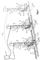
- the support installation comprises a supporting structure consisting of a plurality of hollow vertical columns 2, of a height for example of 2.5 m or more, each equipped with a first horizontal arm 3 and a a second horizontal arm 4, parallel to each other.
- Each first horizontal arm 3 extends cantilevered from its support post 2. It is mounted on a sliding carriage 5 movable vertically.
- the carriage 5 is equipped with rollers and is guided by slides provided on the front face of the column 2, or inside thereof. Its displacement, with the cantilever arm 3 is achieved by means of a vertical worm, schematized by the dashed line 6, integrated within the post 2 and driven in rotation by a motor 7 (for example asynchronous brake motor type).
- the cooperation between the worm 6 and the carriage 5 is carried out conventionally by means of a bronze nut.
- a second nut ensures the safety of the carriage in case of wear of the threads of the first bronze nut.
- This first support arm 3 can be maneuvered in vertical translation substantially from the ground, at least to a height of 1.5 m, and preferably more. Its structure and robustness, as well as those of the support post 2, are adapted according to the maximum loads to be supported.
- the engine 7 is controllable by means of a control pedal 8, double contactor type, directly accessible to the operator near the pole 2, the side of the first support arm 3.
- This control pedal 8 allows the maneuvering of this first support arm 3 at will, uphill or downhill.
- the pedal 8 and the actuator 7 are connected to a control cabinet incorporating a programmable controller 9, whose function will be detailed later.
- the second support arm 4 extends horizontally cantilevered from the post 2. Its horizontal bearing surface 10 is at a fixed height with respect to the ground, corresponding to a level making it possible to perform an operation of welding with comfort. This height is between 0.7 m and 1.30 m, preferably between 0.90 m and 1.10 m.
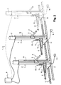
- This second support arm 4 is pivotally mounted on the post 2, around a vertical axis 11, so that it can be retracted on its side, as illustrated in FIG. figure 2 . It is advantageously provided with deactivatable means (not shown) for locking the active position of the support arm 4 (that is to say the position in which the arm 4 is parallel to the first support arm 3, as illustrated figure 1 ).
- the second support arm 4 is slightly offset on the side, relative to the vertical plane of movement of the first support arm 3, so as not to hinder the vertical movement of the latter. It preferably extends over a length slightly greater than that of the first support arm 3, so as will be seen later on, to facilitate the reception of previously stored rods bearing on said first support arm 3.
- the bearing surface 10 of the second support arm 4 consists of a roller 12 which is rotatably mounted around a longitudinal axis 12 '. This roller 12 optimizes the lateral sliding of the rods bearing on the second support arm 4.
- the second support arm 4 there is the presence of two vertical parallel plates, one before 13 and the other rear 13 ', integral with the post 2, spaced from each other here a distance corresponding to the width of said post 2.
- These two plates 13 and 13 ' are each provided with a series of superimposed orifices 14, 14', aligned vertically.
- the orifices 14 of the front plate 13 are each arranged in correspondence with one of the orifices 14 'of the rear plate 13' (that is to say coaxially), to form a horizontal housing 15, able to receive a complementary arm 16, shown in dotted lines.
- the series of superimposed housings 15 form a kind of rack which allows a removable positioning of an additional support arm 16 at the desired level, or a positioning of several additional arms 16, on several levels.
- This or these additional arms 16 extend parallel to the first and second support arms 3, 4. It is or they are slightly offset on the side relative to the vertical plane of displacement of the first support arm 3, to not hinder the vertical movement of the last.
- the various posts 2 are mounted on a rolling track on a single structure 17, to allow their approximation or spacing at will from each other by simple manual push, that in a direction that is perpendicular to the support arms 3, 4 and possibly 16 above .
- each post 2 is equipped with a measuring device 18 making it possible to indicate to the operator the height level of the bearing surface of the first support arm 3, relative to the level of the second support arm 4
- This measuring device 18 may consist of a simple graduated rule; it can also be an encoder with digital display, taking into account the rotation of the shaft of the geared motor 7.
- the support installation 1 comprises a plurality of posts 2, all identical or similar, arranged next to each other on their guide structure 17.
- the various posts 2 are all oriented in the same direction so that their support arms 3, 4 and possibly 16 extend all parallel to each other.
- the operating means 7, 8 of the movable arms 3 of all the posts 2 are connected to the programmable controller 9 ensuring the management of all configurations.
- this automaton 9 is programmed so as to take into account the prior selection of the posts 2 chosen to manufacture an armature (from the set of available poles), to ensure the positioning of the first support arms 3 at the same height level, then to allow the synchronized rise and fall of the different support arms 3 corresponding, this from only one of the control pedals 8 associated with one of the selected poles.
- the controller 9 manages the top and bottom limit switches of the mobile carriages 5, as well as any emergency stops; it also provides thermal control of geared motors 7.
- the operator From the plane of the armature that it must manufacture, the operator therefore selects the support posts 2 that he wishes to use (in location and in number). Then, it correctly positions the different support posts 2 relative to each other, by manual displacement on the guide structure 17.
- first support arms 3 of the various columns 2 selected, juxtaposed, form a horizontal support plane 3 '(called the first horizontal support plane 3'), which is adapted to serve as a removal and reception plane for some of the bars longitudinal constituent of the frame.
- This first support plane 3 ' is vertically movable and its level can be adapted at will by the operator by controlling one of the control pedals 8 between upper and lower extreme heights.
- the second support arms 4 of the various columns 2 selected form a horizontal support plane 4 '(called second support plane 4'), whose height level is fixed, clean, too, to serve as a plan of removal and reception for some longitudinal rods constituent of the frame.
- the optional complementary arms 16 form one or more additional horizontal support planes 16 '.
- These different support planes 3 ', 4' and possibly 16 ' are arranged one above the other (or some for some, depending on the positioning of the first support plane 3'); they are at least partially superimposed, that is to say arranged at least partially in the same vertical space.
- the different support planes 3 ', 4' and 16 ' have the same length, delimited by the support posts 2 of ends; they also have substantially the same width, corresponding to the length of the arms 3, 4 and 16, and they are almost completely superimposed.
- the retraction of the second support arms 4 (performed manually) is effected by pivoting on an angular sector close to 90 °. This retraction makes it possible to almost completely remove the second support plane 4 ', and to release almost completely the vertical space under the first support plane 3'.
- the operator uses the mobility of the first support plane 3 'to weld at a height which is most comfortable for him the high bars on the upper part of the transverse frames (this welding height is a priori as close as possible to the second support plane 4 ').
- this welding height is a priori as close as possible to the second support plane 4 '.
- This mobility then allows the operator to raise the cage formed by the set of upper bars / transverse frames to correctly position these transverse frames (and possibly intermediate frames) relative to the (x) bed (s) of rods skin and bottom, previously arranged on the second support plane 4 'and optionally on the or additional support planes 16'. This avoids the operator having to wear said rods during the welding operation.
- the operator is assisted by the measuring device 18.
- the armature is deposited on the ground, or on a mobile storage structure, by lowering the mobile plane 3 ', after retraction of the support arms 4 and removal of any additional arms 16.
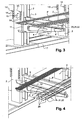
- the first operation consists in depositing all the bars necessary for the production of the series of pieces on the mobile support plane 3 'formed by the juxtaposition of the first support arms 3, in the retracted position, close to the posts 2; then, in the package, is selected by sliding forward of the high bars 20, skin 21 and bottom 22 necessary for the manufacture of the frame.
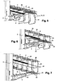
- the transverse frames 23 are positioned in abutment on the high-wire bars 20, themselves bearing on the first movable support plane 3 ', and said upper bars 20 are welded on the upper part. said transverse frames 23 ( figure 5 ).
- This welding operation is performed at a level as close as possible to the second support plane 4 ', considered as the ergonomically optimum welding plane. It can in particular be made approximately 100 mm above the support plane 4 ', taking into account the maximum diameter of the threads and the thickness of the movable arms 3. It should be noted here that the installation can advantageously be equipped with a system sensors to block the descent of the arms 3 before they interfere with the rods placed on the fixed arms 4.
- the following operation, illustrated on the figure 6 is to raise the movable support plane 3 'until the second support plane 4' reaches the level at which the skin bars 21 are to be welded to the sides of the frames 23. The corresponding weld is then performed by the operator.
- the movable supporting plane 3 ' is further raised until the bottom bars 22 come into contact with the lower part of the frames 23, and then said bottom bars 22 are welded to said transverse frames 23.
- the armature 24 thus manufactured is raised to release the second support plane 4 '.
- the second support arms 4 can then be retracted laterally to release the vertical bulk of the armature ( figure 8 ).
- the installation is ready for a new manufacturing cycle, after repositioning the second support arms 4 parallel to the first movable arms 3.
- the operational implementation of the installation may be somewhat different from that described above, depending on the structure of the reinforcement to be manufactured, or depending on the habits or experiences of the welders.
- the transverse frames 23 may very well be positioned around the various bars 20, 21, and 22 bearing on the movable arms 3 (before the transfer of the skin bars 21 and bottom 22 on the arms 4), in order to limit their necessary insertion opening.
- Additional arms 16 are used for the creation of complementary support planes, in particular for the manufacture of more complex reinforcement, including including intermediate frames (in particular an additional horizontal plane will be created by additional closed frame in the section of the room).
- all the support arms 3, 4 and 16 may be mounted on the same supporting structure, for example fixed to a support wall.
- a simplified installation can consist of a single support post equipped with a mobile structure (formed of at least two parallel arms) constituting the first movable support plane 3 ', and a fixed structure (formed at least two parallel arms) constituting the second support plane 4 '; the mobile structure can then advantageously consist of one or more central arms associated with laterally movable end arms.
- the ergonomic welding station relieves the work of welders by limiting their physical effort and minimizing gestures and handling parts. It helps to improve working conditions and therefore the quality of it.
- this post optimizes the assembly. It respects the natural flow of production and the work of the operator which leads to the finished product without artificial creation of semi-finished products.
- the height alignment of the rods on the transverse frames is naturally done by the synchronization of the supports. It is no longer necessary to lift the bars to point the weld. This item optimizes assembly and allows productivity gains.
- this installation adapts to all configurations.
- the different support posts 2, aligned on rails, allow use in groups, depending on the geometry of the frame to be assembled, the management of the different configurations being provided by the programmable controller.
Landscapes
- Engineering & Computer Science (AREA)
- Mechanical Engineering (AREA)
- Wire Processing (AREA)
- Pressure Welding/Diffusion-Bonding (AREA)
- Rod-Shaped Construction Members (AREA)
- Forging (AREA)
- Manufacturing Of Tubular Articles Or Embedded Moulded Articles (AREA)
- Superconductors And Manufacturing Methods Therefor (AREA)
Claims (10)
- Stützsystem zur Herstellung von Metallverstärkungen, insbesondere von Betonbewehrungen, die aus waagerechten Bewehrungslagen bestehen, die auf mehreren Höhlen durch Querrahmen verbunden sind, wobei diese waagerechten Bewehrungslagen obere Stäbe, untere Stäbe rund eventuell mittlere seitliche Stäbe umfassen, wobei dieses System umfasst:- mindestens zwei erste parallele Stützarme (3), die in derselben Horizontalebene angeordnet sind, wobei diese ersten Arme (3) freitragend an eine Tragstruktur (2) befestigt und mit steuerbaren Mitteln (5, 6, 7, 8) verbunden sind, die deren gleichzeitige vertikale Bewegung parallel zueinander erlauben, um eine erste horizontale Stützebene (3') zu bilden, die vertikal beweglich ist, und- mindestens zwei zweite parallele Stützarme (4), die in derselben Horizontalebene angeordnet sind, wobei diese zweiten Arme (4) freitragend an diese Tragstruktur (2) befestigt sind und parallel zu den ersten Stützarmen (3) verlaufen, um eine zweite horizontale Stützebene (4') zu bilden, wobei diese erste (3') und zweite (4') Stützebene mindestens teilweise übereinander liegen,dadurch gekennzeichnet, dass die zweiten Stützarme (4) auf einer feststehenden Höhe, die zwischen 0,70 m und 1,30 m liegt, an der Tragstruktur (2) befestigt sind und relativ zur vertikalen Bewegungsebene der ersten Stützarme (3) leicht seitlich versetzt sind, um die vertikale Bewegung dieser Letzteren nicht zu behindern, wobei die zweiten Stützarme (4) auf einer Länge verlaufen, die etwas größer ist als die der ersten Stützarme (3), und um eine Vertikalachse (11) schwenkbar an der Tragstruktur (2) befestigt sind, um ihr Einziehen außerhalb mindestens eines Teils des vertikalen Raumbedarfs des ersten Stützebene (3') zu erlauben,
wobei die erste Ebene (3') mindestens zwischen einer unteren Höhe, die leicht über der zweiten Ebene (4') liegt, und einer oberen Endhöhe vertikal beweglich ist, die von dieser unteren Höhe mindestens um den Höchstabstand beabstandet ist, der die oberen Stäbe und die unteren Stäbe der verschiedenen möglichen Bewehrungsmodelle trennt, um eine Schweißung, an diesen Querrahmen, der oberen Stäbe zu erlauben, die auf den ersten Armen (3) etwas über der zweiten Ebene (4') liegen, und dann eine Schweißung, an diesen Querrahmen, der eventuellen mittleren seitlichen Stäbe und der unteren Stäbe zu erlauben, die auf den zweiten Armen (4) liegen, und dies nach der Hebung, durch diese ersten Arme (3), des Verbands aus oberen Stäbe/Querrahmen, wobei die Gesamtheit dieser Schweißoperationen stets auf der gleichen Ebene oder im Wesentlichen auf der gleichen Ebene durchgeführt werden kann. - System nach Anspruch 1, dadurch gekennzeichnet, dass es eine Tragstruktur umfasst, die aus mehreren vertikalen Pfosten (2) besteht, die alle mit einem dieser beweglichen ersten Stützarme (3) und einem der zweiten Stützarme (4) ausgestattet sind.
- System nach Anspruch 2, dadurch gekennzeichnet, dass die vertikalen Pfosten (2) auf einer Schienenstruktur (17) rollend montiert sind, die entlang einer Richtung rechtwinkelig zu den ersten und zweiten Stützarmen (3, 4) verläuft, um eine Einstellung des Abstands zwischen diesen Pfosten (2) zuzulassen, und auch, um eine Wahl der Zahl der (2) Pfosten zu erlauben, die zur Herstellung der gewünschten Bewehrung benötigt werden.
- System nach Anspruch 3, dadurch gekennzeichnet, dass jeder Pfosten (2) mit einem Steuerpedal (8) versehen ist, das mit einem programmierbaren Automaten (9) verbunden ist, der nach der Wahl der verschiedenen Pfosten (2), die zur Herstellung der gewünschten Bewehrung gewählt werden, die synchronisierte Hebung oder Senkung der verschiedenen beweglichen Stützarme (3) gewährleistet, die die erste Stützebene (3') bilden, und dies von einem dieser Steuerpedale (8) aus.
- System nach einem der Ansprüche 1 bis 4, dadurch gekennzeichnet, dass die ersten Stützarme (3) alle mithilfe eines vertikal beweglichen Wagens (5) an ihre Tragstruktur (2) montiert werden, wobei dieser Wagen (5) von einer vertikalen Schnecke (6) bewegt wird, die durch einen Antriebsmotor (7) gedreht wird.
- System nach einem der Ansprüche 1 bis 5, dadurch gekennzeichnet, dass die Tragstruktur (2) mindestens zwei Aufnahmen (15) umfasst, um mindestens zwei abnehmbare Zusatzstützarme (16) auszunehmen, die parallel zu den ersten und zweiten Stützarmen (3, 4) sind und die Bildung einer dritten Stützebene (16') über der zweiten Stützebene (4') zu erlauben.
- System nach Anspruch 6, dadurch gekennzeichnet, dass es zwei übereinander liegende Gruppen von Aufnahmen (15) zur Aufnahme dieser abnehmbaren Zusatzstützarme (16) umfasst, die eine Positionierungsauswahl ermöglichen, um die vertikale Höhe der dritten Stützebene (16') anzupassen, oder die Möglichkeit, mehrere Zusatzstützebenen (16') herzustellen.
- System nach einem der Ansprüche 1 bis 7, dadurch gekennzeichnet, dass die Tragstruktur (2) eine Messvorrichtung (18) umfasst, die es erlaubt, die Höhe der ersten beweglichen Stützebene (3') relativ zu einer Referenz zu messen, und insbesondere relativ zur Höhe der zweiten Stützebene (4').
- Verfahren zur Herstellung einer Metallverstärkung, bestehend aus waagerechten Bewehrungslagen (20, 21, 22) bestehen, die auf mehreren Höhen durch Querrahmen (23) verbunden sind, wobei diese waagerechten Bewehrungslagen obere Stäbe (20), untere Stäbe (22) und eventuell mittlere seitliche Stäbe (21) umfassen, um das System nach den Ansprüche 1 bis 8 herzustellen, wobei dieses Verfahren umfasst:- das Positionieren der oberen Stäbe (20) auf eine erste Stützebene (3') und der unteren Stäbe (22), eventuell mit den mittleren seitlichen Stäbe (21), auf eine zweite Stützebene (4'), wobei diese zweite Stützebene (4') direkt unter der ersten (3') angeordnet ist, wobei die Gesamtheit der Bewehrungslagen (20, 21, 22) von den Querrahmen umschlossen wird,- das Schweißen der oberen Stäbe (20) an die Querrahmen (23),- das Heben der Einheit aus oberen Stäben (20)/Querrahmen (23), während die zweite Stützebene (4) festgehalten wird, um die ordentliche Schweißung der eventuellen mittleren seitlichen Stäbe (21) und dann der unteren Stäbe (22) durchzuführen, wodurch die Schweißoperationen stets auf der gleichen Ebene oder im Wesentlichen auf der gleichen Ebene durchgeführt werden können.
- Verfahren nach Anspruch 9, dadurch gekennzeichnet, dass es umfasst:- das Positionieren einer Serie von waagerechten Bewehrungslagen auf eine erste Stützebene (3'),- das Wählen, aus dieser Serie, der verschiedenen waagerechten Bewehrungsstäbe (20, 21, 22), die zur Herstellung einer Bewehrung benötigt werden, indem sie zum freitragenden Ende der ersten Stützarme (3) hin gebracht werden,- das Positionieren der Querrahmen (23) an diese Auswahl von Bewehrungslagen (20, 21, 22),- das Umlegen der unteren Stäbe (22) und eventuell der mittleren seitlichen Stäbe (21) auf die zweiten Stützarme (4),- das Schweißen der oberen Stäbe (20) an die Querrahmen (23),- das Heben der Einheit aus oberen Stäben (20)/Querrahmen (23) mithilfe der ersten Arme (3), während die zweite Stützebene (4') festgehalten wird, um die Schweißung der eventuellen mittleren seitlichen Stäbe (21) und dann der unteren Stäbe (22) durchzuführen.
Applications Claiming Priority (2)
| Application Number | Priority Date | Filing Date | Title |
|---|---|---|---|
| FR0608585A FR2906489B1 (fr) | 2006-09-29 | 2006-09-29 | Installation support pour la fabrication d'armatures metalliques |
| PCT/FR2007/052044 WO2008040903A1 (fr) | 2006-09-29 | 2007-09-28 | Installation support pour la fabrication d'armatures metalliques et son procede de mise en oeuvre |
Publications (2)
| Publication Number | Publication Date |
|---|---|
| EP2091677A1 EP2091677A1 (de) | 2009-08-26 |
| EP2091677B1 true EP2091677B1 (de) | 2010-08-25 |
Family
ID=38330763
Family Applications (1)
| Application Number | Title | Priority Date | Filing Date |
|---|---|---|---|
| EP07823878A Not-in-force EP2091677B1 (de) | 2006-09-29 | 2007-09-28 | Stützsystem zur herstellung von metallverstärkungen und implementierungsverfahren dafür |
Country Status (5)
| Country | Link |
|---|---|
| EP (1) | EP2091677B1 (de) |
| AT (1) | ATE478744T1 (de) |
| DE (1) | DE602007008758D1 (de) |
| FR (1) | FR2906489B1 (de) |
| WO (1) | WO2008040903A1 (de) |
Cited By (2)
| Publication number | Priority date | Publication date | Assignee | Title |
|---|---|---|---|---|
| CN104097009A (zh) * | 2014-07-15 | 2014-10-15 | 南车南京浦镇车辆有限公司 | 通用式底架正装胎 |
| WO2025214563A1 (en) * | 2024-04-12 | 2025-10-16 | Gmt Robotics Aps | Apparatus for feeding reinforcement elements into an assembly station, an assembly station, a system and a method of assembling a reinforcement cage |
Families Citing this family (14)
| Publication number | Priority date | Publication date | Assignee | Title |
|---|---|---|---|---|
| CN102294616A (zh) * | 2011-08-30 | 2011-12-28 | 成都科盛石油科技有限公司 | 工件二维运送装置 |
| CN103538057B (zh) * | 2013-10-22 | 2017-01-25 | 昆山中士设备工业有限公司 | 能准确定位的机械手以及协助机械手准确定位的货架 |
| CN104384403B (zh) * | 2014-09-22 | 2016-05-25 | 山东建筑大学 | 一种钢筋骨架成型机双向尺寸调整装置 |
| CN107378332A (zh) * | 2017-07-31 | 2017-11-24 | 安徽华众焊业有限公司 | 一种结构简单的电焊装置 |
| CN109665215B (zh) * | 2019-03-01 | 2024-03-01 | 江苏耀坤液压股份有限公司 | 一种大臂管输送支撑保护组件 |
| WO2020187379A1 (en) * | 2019-03-19 | 2020-09-24 | German Machine Technics Aps | Assembly machine and a method for manufacturing reinforcement structures |
| DK180334B1 (en) * | 2019-03-19 | 2020-12-04 | Gmt Robotics Aps | Assembly machine and method for assembling reinforced structures |
| CN111421086B (zh) * | 2020-04-01 | 2021-09-21 | 安徽永利建设工程有限公司 | 一种节能环保型建筑材料加工设备 |
| CN111558675A (zh) * | 2020-05-15 | 2020-08-21 | 合肥皖兴建设工程有限公司 | 一种装配式pc预制件钢筋骨架制作工艺 |
| CN112170738A (zh) * | 2020-11-04 | 2021-01-05 | 重庆建工市政交通工程有限责任公司 | 一种钢筋笼制作设备及其使用方法 |
| CN114161051B (zh) * | 2021-11-11 | 2024-02-13 | 河南沃克曼建设工程有限公司 | 垃圾焚烧发电厂立式锅炉基础施工组合平台及施工方法 |
| CN117226459B (zh) * | 2023-11-08 | 2024-02-09 | 之江实验室 | 传动系统连杆的安装工装 |
| WO2026104952A1 (en) * | 2024-11-14 | 2026-05-21 | Ingabbia Srl | Apparatus for assembling metal cages |
| CN120133804B (zh) * | 2025-02-07 | 2025-11-25 | 浙江交工金筑交通建设有限公司 | 一种焊接设备及用于盖梁加工的焊接方法 |
Family Cites Families (5)
| Publication number | Priority date | Publication date | Assignee | Title |
|---|---|---|---|---|
| JPS642751A (en) * | 1987-06-26 | 1989-01-06 | Taisei Corp | Reinforcement assembly device |
| IT1273800B (it) * | 1994-02-10 | 1997-07-10 | Schnell Srl | Metodo e apparecchiatura per realizzare gabbie metalliche per cemento armato e gabbia metallica cosi' ottenuta |
| IT1288852B1 (it) * | 1996-02-22 | 1998-09-25 | Piegatrici Macch Elettr | Procedimento per la realizzazione di gabbie metalliche per cemento armato e relativo dispositivo |
| IT1285930B1 (it) * | 1996-06-07 | 1998-06-26 | Schnell Spa | Apparecchiatura per realizzare gabbie metalliche per cemento armato |
| US20020157254A1 (en) * | 2000-08-09 | 2002-10-31 | Marcel Wirth | Method to form metallic cages for reinforcement and relative device |
-
2006
- 2006-09-29 FR FR0608585A patent/FR2906489B1/fr active Active
-
2007
- 2007-09-28 WO PCT/FR2007/052044 patent/WO2008040903A1/fr not_active Ceased
- 2007-09-28 EP EP07823878A patent/EP2091677B1/de not_active Not-in-force
- 2007-09-28 DE DE602007008758T patent/DE602007008758D1/de active Active
- 2007-09-28 AT AT07823878T patent/ATE478744T1/de not_active IP Right Cessation
Cited By (3)
| Publication number | Priority date | Publication date | Assignee | Title |
|---|---|---|---|---|
| CN104097009A (zh) * | 2014-07-15 | 2014-10-15 | 南车南京浦镇车辆有限公司 | 通用式底架正装胎 |
| CN104097009B (zh) * | 2014-07-15 | 2016-01-13 | 南车南京浦镇车辆有限公司 | 通用式底架正装胎 |
| WO2025214563A1 (en) * | 2024-04-12 | 2025-10-16 | Gmt Robotics Aps | Apparatus for feeding reinforcement elements into an assembly station, an assembly station, a system and a method of assembling a reinforcement cage |
Also Published As
| Publication number | Publication date |
|---|---|
| WO2008040903A1 (fr) | 2008-04-10 |
| DE602007008758D1 (de) | 2010-10-07 |
| ATE478744T1 (de) | 2010-09-15 |
| FR2906489A1 (fr) | 2008-04-04 |
| EP2091677A1 (de) | 2009-08-26 |
| FR2906489B1 (fr) | 2009-05-29 |
Similar Documents
| Publication | Publication Date | Title |
|---|---|---|
| EP2091677A1 (de) | Stützsystem zur herstellung von metallverstärkungen und implementierungsverfahren dafür | |
| EP2401091B1 (de) | Verfahren zum modifizieren des abstands zwischen den rollen einer richtmaschine, richtmaschine und vorrichtung zum implementieren des verfahrens | |
| EP0115357A2 (de) | Montage- und/oder Bearbeitungsanlage für Werkstücke, welche durch laufende und arretierbare Werkstückträger getragen werden | |
| EP0307331B1 (de) | Einrichtung zum Wiederherstellen und Kontrollieren von beschädigten Fahrzeugkarosserien | |
| EP0057128B1 (de) | Vorrichtung zum Auswechseln von Schwellen bei Eisenbahngleisen und Verfahren zur Benutzung dieser Vorrichtung | |
| FR2459769A1 (fr) | Installation pour le stockage de materiau en barres et pour l'amenee automatique et programmee de ce materiau a une machine a tronconner | |
| EP0133113A1 (de) | Vorrichtung mit leicht zu verändernder Wölbung zum Biegen und Härten von Glasscheiben | |
| WO1996021611A1 (fr) | Dispositif de croisement de convoyeurs a palettes et dispositif de changement de palette pour convoyeur a palettes | |
| EP1127654A1 (de) | Verfahren und Vorrichtung zum Stumpfschweissen von metallischen Blechen | |
| FR2952842A1 (fr) | Ligne d'assemblage d'un moteur d'aeronef | |
| CA2101580C (fr) | Machine pour l'epluchage de salades | |
| EP0125716A1 (de) | Verfahren und Vorrichtung zum Zuführen von Querdrähten zu Metallgitterschweissmaschinen | |
| EP0541689A1 (de) | Stop-positioniervorrichtung für ein flurförderfahrzeug. | |
| BE1006835A3 (fr) | Installation de coupe de barres metalliques. | |
| WO1987005544A1 (fr) | Machine integree flexible, pour fabriquer automatiquement des armatures metalliques, notamment pour le beton arme | |
| FR2541562A1 (fr) | Procede de greffage automatique de la vigne et machine comportant application de ce procede | |
| CH625724A5 (de) | ||
| EP4414095A1 (de) | Gestellsystem, walzanlage mit einem solchen system und verfahren zur implementierung solch eines systems | |
| CH663780A5 (fr) | Installation de stockage dynamique, notamment pour produits fragiles tels que fromages. | |
| EP0315263A1 (de) | Mobiles Regalmagazin für die Reifung von synthetischen Quellrohlingen | |
| FR2631099A1 (fr) | Dispositif de positionnement de pieces metalliques contre un element metallique porteur allonge | |
| EP0898891A1 (de) | Teiglingformmaschine | |
| FR2598336A1 (fr) | Manipulateur pour l'alimentation automatique des machines pour la centrifugation des bobines de fil | |
| FR2773436A1 (fr) | Dispositif et procede pour scarifier des patons de pain ou analogues | |
| FR2503680A1 (fr) | Dispositif permettant l'execution d'operations sur une ligne, notamment en fonderie pour les operations de depose de noyaux et de coulee |
Legal Events
| Date | Code | Title | Description |
|---|---|---|---|
| PUAI | Public reference made under article 153(3) epc to a published international application that has entered the european phase |
Free format text: ORIGINAL CODE: 0009012 |
|
| 17P | Request for examination filed |
Effective date: 20090428 |
|
| AK | Designated contracting states |
Kind code of ref document: A1 Designated state(s): AT BE BG CH CY CZ DE DK EE ES FI FR GB GR HU IE IS IT LI LT LU LV MC MT NL PL PT RO SE SI SK TR |
|
| 17Q | First examination report despatched |
Effective date: 20090818 |
|
| DAX | Request for extension of the european patent (deleted) | ||
| GRAP | Despatch of communication of intention to grant a patent |
Free format text: ORIGINAL CODE: EPIDOSNIGR1 |
|
| GRAS | Grant fee paid |
Free format text: ORIGINAL CODE: EPIDOSNIGR3 |
|
| GRAA | (expected) grant |
Free format text: ORIGINAL CODE: 0009210 |
|
| AK | Designated contracting states |
Kind code of ref document: B1 Designated state(s): AT BE BG CH CY CZ DE DK EE ES FI FR GB GR HU IE IS IT LI LT LU LV MC MT NL PL PT RO SE SI SK TR |
|
| REG | Reference to a national code |
Ref country code: GB Ref legal event code: FG4D Free format text: NOT ENGLISH |
|
| REG | Reference to a national code |
Ref country code: CH Ref legal event code: EP |
|
| REG | Reference to a national code |
Ref country code: IE Ref legal event code: FG4D Free format text: LANGUAGE OF EP DOCUMENT: FRENCH |
|
| REF | Corresponds to: |
Ref document number: 602007008758 Country of ref document: DE Date of ref document: 20101007 Kind code of ref document: P |
|
| REG | Reference to a national code |
Ref country code: NL Ref legal event code: T3 |
|
| LTIE | Lt: invalidation of european patent or patent extension |
Effective date: 20100825 |
|
| PG25 | Lapsed in a contracting state [announced via postgrant information from national office to epo] |
Ref country code: FI Free format text: LAPSE BECAUSE OF FAILURE TO SUBMIT A TRANSLATION OF THE DESCRIPTION OR TO PAY THE FEE WITHIN THE PRESCRIBED TIME-LIMIT Effective date: 20100825 Ref country code: AT Free format text: LAPSE BECAUSE OF FAILURE TO SUBMIT A TRANSLATION OF THE DESCRIPTION OR TO PAY THE FEE WITHIN THE PRESCRIBED TIME-LIMIT Effective date: 20100825 Ref country code: LT Free format text: LAPSE BECAUSE OF FAILURE TO SUBMIT A TRANSLATION OF THE DESCRIPTION OR TO PAY THE FEE WITHIN THE PRESCRIBED TIME-LIMIT Effective date: 20100825 |
|
| PG25 | Lapsed in a contracting state [announced via postgrant information from national office to epo] |
Ref country code: BG Free format text: LAPSE BECAUSE OF FAILURE TO SUBMIT A TRANSLATION OF THE DESCRIPTION OR TO PAY THE FEE WITHIN THE PRESCRIBED TIME-LIMIT Effective date: 20101125 Ref country code: CY Free format text: LAPSE BECAUSE OF FAILURE TO SUBMIT A TRANSLATION OF THE DESCRIPTION OR TO PAY THE FEE WITHIN THE PRESCRIBED TIME-LIMIT Effective date: 20100825 Ref country code: IS Free format text: LAPSE BECAUSE OF FAILURE TO SUBMIT A TRANSLATION OF THE DESCRIPTION OR TO PAY THE FEE WITHIN THE PRESCRIBED TIME-LIMIT Effective date: 20101225 Ref country code: PL Free format text: LAPSE BECAUSE OF FAILURE TO SUBMIT A TRANSLATION OF THE DESCRIPTION OR TO PAY THE FEE WITHIN THE PRESCRIBED TIME-LIMIT Effective date: 20100825 Ref country code: PT Free format text: LAPSE BECAUSE OF FAILURE TO SUBMIT A TRANSLATION OF THE DESCRIPTION OR TO PAY THE FEE WITHIN THE PRESCRIBED TIME-LIMIT Effective date: 20101227 Ref country code: SI Free format text: LAPSE BECAUSE OF FAILURE TO SUBMIT A TRANSLATION OF THE DESCRIPTION OR TO PAY THE FEE WITHIN THE PRESCRIBED TIME-LIMIT Effective date: 20100825 |
|
| REG | Reference to a national code |
Ref country code: IE Ref legal event code: FD4D |
|
| PG25 | Lapsed in a contracting state [announced via postgrant information from national office to epo] |
Ref country code: LV Free format text: LAPSE BECAUSE OF FAILURE TO SUBMIT A TRANSLATION OF THE DESCRIPTION OR TO PAY THE FEE WITHIN THE PRESCRIBED TIME-LIMIT Effective date: 20100825 Ref country code: SE Free format text: LAPSE BECAUSE OF FAILURE TO SUBMIT A TRANSLATION OF THE DESCRIPTION OR TO PAY THE FEE WITHIN THE PRESCRIBED TIME-LIMIT Effective date: 20100825 Ref country code: GR Free format text: LAPSE BECAUSE OF FAILURE TO SUBMIT A TRANSLATION OF THE DESCRIPTION OR TO PAY THE FEE WITHIN THE PRESCRIBED TIME-LIMIT Effective date: 20101126 |
|
| PG25 | Lapsed in a contracting state [announced via postgrant information from national office to epo] |
Ref country code: IE Free format text: LAPSE BECAUSE OF FAILURE TO SUBMIT A TRANSLATION OF THE DESCRIPTION OR TO PAY THE FEE WITHIN THE PRESCRIBED TIME-LIMIT Effective date: 20100825 Ref country code: DK Free format text: LAPSE BECAUSE OF FAILURE TO SUBMIT A TRANSLATION OF THE DESCRIPTION OR TO PAY THE FEE WITHIN THE PRESCRIBED TIME-LIMIT Effective date: 20100825 Ref country code: MC Free format text: LAPSE BECAUSE OF NON-PAYMENT OF DUE FEES Effective date: 20100930 |
|
| PG25 | Lapsed in a contracting state [announced via postgrant information from national office to epo] |
Ref country code: RO Free format text: LAPSE BECAUSE OF FAILURE TO SUBMIT A TRANSLATION OF THE DESCRIPTION OR TO PAY THE FEE WITHIN THE PRESCRIBED TIME-LIMIT Effective date: 20100825 Ref country code: EE Free format text: LAPSE BECAUSE OF FAILURE TO SUBMIT A TRANSLATION OF THE DESCRIPTION OR TO PAY THE FEE WITHIN THE PRESCRIBED TIME-LIMIT Effective date: 20100825 Ref country code: IT Free format text: LAPSE BECAUSE OF FAILURE TO SUBMIT A TRANSLATION OF THE DESCRIPTION OR TO PAY THE FEE WITHIN THE PRESCRIBED TIME-LIMIT Effective date: 20100825 Ref country code: SK Free format text: LAPSE BECAUSE OF FAILURE TO SUBMIT A TRANSLATION OF THE DESCRIPTION OR TO PAY THE FEE WITHIN THE PRESCRIBED TIME-LIMIT Effective date: 20100825 Ref country code: CZ Free format text: LAPSE BECAUSE OF FAILURE TO SUBMIT A TRANSLATION OF THE DESCRIPTION OR TO PAY THE FEE WITHIN THE PRESCRIBED TIME-LIMIT Effective date: 20100825 |
|
| PG25 | Lapsed in a contracting state [announced via postgrant information from national office to epo] |
Ref country code: ES Free format text: LAPSE BECAUSE OF FAILURE TO SUBMIT A TRANSLATION OF THE DESCRIPTION OR TO PAY THE FEE WITHIN THE PRESCRIBED TIME-LIMIT Effective date: 20101206 |
|
| PLBE | No opposition filed within time limit |
Free format text: ORIGINAL CODE: 0009261 |
|
| STAA | Information on the status of an ep patent application or granted ep patent |
Free format text: STATUS: NO OPPOSITION FILED WITHIN TIME LIMIT |
|
| 26N | No opposition filed |
Effective date: 20110526 |
|
| REG | Reference to a national code |
Ref country code: DE Ref legal event code: R097 Ref document number: 602007008758 Country of ref document: DE Effective date: 20110526 |
|
| PG25 | Lapsed in a contracting state [announced via postgrant information from national office to epo] |
Ref country code: MT Free format text: LAPSE BECAUSE OF FAILURE TO SUBMIT A TRANSLATION OF THE DESCRIPTION OR TO PAY THE FEE WITHIN THE PRESCRIBED TIME-LIMIT Effective date: 20100825 |
|
| REG | Reference to a national code |
Ref country code: CH Ref legal event code: PL |
|
| PG25 | Lapsed in a contracting state [announced via postgrant information from national office to epo] |
Ref country code: CH Free format text: LAPSE BECAUSE OF NON-PAYMENT OF DUE FEES Effective date: 20110930 Ref country code: LI Free format text: LAPSE BECAUSE OF NON-PAYMENT OF DUE FEES Effective date: 20110930 |
|
| PG25 | Lapsed in a contracting state [announced via postgrant information from national office to epo] |
Ref country code: HU Free format text: LAPSE BECAUSE OF FAILURE TO SUBMIT A TRANSLATION OF THE DESCRIPTION OR TO PAY THE FEE WITHIN THE PRESCRIBED TIME-LIMIT Effective date: 20110226 Ref country code: LU Free format text: LAPSE BECAUSE OF NON-PAYMENT OF DUE FEES Effective date: 20100928 |
|
| PG25 | Lapsed in a contracting state [announced via postgrant information from national office to epo] |
Ref country code: TR Free format text: LAPSE BECAUSE OF FAILURE TO SUBMIT A TRANSLATION OF THE DESCRIPTION OR TO PAY THE FEE WITHIN THE PRESCRIBED TIME-LIMIT Effective date: 20100825 |
|
| REG | Reference to a national code |
Ref country code: NL Ref legal event code: TD Effective date: 20140814 |
|
| REG | Reference to a national code |
Ref country code: FR Ref legal event code: CD Owner name: ARMA-PLUS, FR Effective date: 20140729 |
|
| REG | Reference to a national code |
Ref country code: DE Ref legal event code: R081 Ref document number: 602007008758 Country of ref document: DE Owner name: ARMA-PLUS, FR Free format text: FORMER OWNER: ARBOSS, SAINT-HERBLAIN, FR Effective date: 20140724 Ref country code: DE Ref legal event code: R082 Ref document number: 602007008758 Country of ref document: DE Representative=s name: PATENTANWAELTE VOLLMANN & HEMMER, DE Effective date: 20140724 |
|
| REG | Reference to a national code |
Ref country code: FR Ref legal event code: PLFP Year of fee payment: 10 |
|
| REG | Reference to a national code |
Ref country code: FR Ref legal event code: PLFP Year of fee payment: 11 |
|
| PGFP | Annual fee paid to national office [announced via postgrant information from national office to epo] |
Ref country code: FR Payment date: 20170511 Year of fee payment: 17 Ref country code: GB Payment date: 20170707 Year of fee payment: 11 |
|
| PGFP | Annual fee paid to national office [announced via postgrant information from national office to epo] |
Ref country code: NL Payment date: 20170921 Year of fee payment: 11 Ref country code: BE Payment date: 20170714 Year of fee payment: 11 |
|
| REG | Reference to a national code |
Ref country code: FR Ref legal event code: PLFP Year of fee payment: 12 |
|
| REG | Reference to a national code |
Ref country code: DE Ref legal event code: R119 Ref document number: 602007008758 Country of ref document: DE |
|
| REG | Reference to a national code |
Ref country code: NL Ref legal event code: MM Effective date: 20181001 |
|
| GBPC | Gb: european patent ceased through non-payment of renewal fee |
Effective date: 20180928 |
|
| REG | Reference to a national code |
Ref country code: BE Ref legal event code: MM Effective date: 20180930 |
|
| PG25 | Lapsed in a contracting state [announced via postgrant information from national office to epo] |
Ref country code: NL Free format text: LAPSE BECAUSE OF NON-PAYMENT OF DUE FEES Effective date: 20181001 |
|
| PG25 | Lapsed in a contracting state [announced via postgrant information from national office to epo] |
Ref country code: DE Free format text: LAPSE BECAUSE OF NON-PAYMENT OF DUE FEES Effective date: 20190402 |
|
| PG25 | Lapsed in a contracting state [announced via postgrant information from national office to epo] |
Ref country code: BE Free format text: LAPSE BECAUSE OF NON-PAYMENT OF DUE FEES Effective date: 20180930 |
|
| PG25 | Lapsed in a contracting state [announced via postgrant information from national office to epo] |
Ref country code: GB Free format text: LAPSE BECAUSE OF NON-PAYMENT OF DUE FEES Effective date: 20180928 |
|
| PG25 | Lapsed in a contracting state [announced via postgrant information from national office to epo] |
Ref country code: FR Free format text: LAPSE BECAUSE OF NON-PAYMENT OF DUE FEES Effective date: 20230930 |