EP2092088B1 - Procédé de fabrication d'au moins une partie d'un dispositif destiné à un engin de terrassement ou à un engin servant à manipuler des matériaux, faisant intervenir de la fonte ductile ayant subie une trempe étagée bainitique - Google Patents
Procédé de fabrication d'au moins une partie d'un dispositif destiné à un engin de terrassement ou à un engin servant à manipuler des matériaux, faisant intervenir de la fonte ductile ayant subie une trempe étagée bainitique Download PDFInfo
- Publication number
- EP2092088B1 EP2092088B1 EP07861108.4A EP07861108A EP2092088B1 EP 2092088 B1 EP2092088 B1 EP 2092088B1 EP 07861108 A EP07861108 A EP 07861108A EP 2092088 B1 EP2092088 B1 EP 2092088B1
- Authority
- EP
- European Patent Office
- Prior art keywords
- tiltrotator
- rotator
- max
- ductile iron
- temperature
- Prior art date
- Legal status (The legal status is an assumption and is not a legal conclusion. Google has not performed a legal analysis and makes no representation as to the accuracy of the status listed.)
- Not-in-force
Links
Images




Classifications
-
- C—CHEMISTRY; METALLURGY
- C21—METALLURGY OF IRON
- C21D—MODIFYING THE PHYSICAL STRUCTURE OF FERROUS METALS; GENERAL DEVICES FOR HEAT TREATMENT OF FERROUS OR NON-FERROUS METALS OR ALLOYS; MAKING METAL MALLEABLE, e.g. BY DECARBURISATION OR TEMPERING
- C21D5/00—Heat treatments of cast-iron
-
- C—CHEMISTRY; METALLURGY
- C21—METALLURGY OF IRON
- C21D—MODIFYING THE PHYSICAL STRUCTURE OF FERROUS METALS; GENERAL DEVICES FOR HEAT TREATMENT OF FERROUS OR NON-FERROUS METALS OR ALLOYS; MAKING METAL MALLEABLE, e.g. BY DECARBURISATION OR TEMPERING
- C21D9/00—Heat treatment, e.g. annealing, hardening, quenching or tempering, adapted for particular articles; Furnaces therefor
-
- C—CHEMISTRY; METALLURGY
- C21—METALLURGY OF IRON
- C21D—MODIFYING THE PHYSICAL STRUCTURE OF FERROUS METALS; GENERAL DEVICES FOR HEAT TREATMENT OF FERROUS OR NON-FERROUS METALS OR ALLOYS; MAKING METAL MALLEABLE, e.g. BY DECARBURISATION OR TEMPERING
- C21D9/00—Heat treatment, e.g. annealing, hardening, quenching or tempering, adapted for particular articles; Furnaces therefor
- C21D9/0068—Heat treatment, e.g. annealing, hardening, quenching or tempering, adapted for particular articles; Furnaces therefor for particular articles not mentioned below
-
- C—CHEMISTRY; METALLURGY
- C22—METALLURGY; FERROUS OR NON-FERROUS ALLOYS; TREATMENT OF ALLOYS OR NON-FERROUS METALS
- C22C—ALLOYS
- C22C37/00—Cast-iron alloys
- C22C37/04—Cast-iron alloys containing spheroidal graphite
-
- E—FIXED CONSTRUCTIONS
- E02—HYDRAULIC ENGINEERING; FOUNDATIONS; SOIL SHIFTING
- E02F—DREDGING; SOIL-SHIFTING
- E02F3/00—Dredgers; Soil-shifting machines
- E02F3/04—Dredgers; Soil-shifting machines mechanically-driven
- E02F3/28—Dredgers; Soil-shifting machines mechanically-driven with digging tools mounted on a dipper- or bucket-arm, i.e. there is either one arm or a pair of arms, e.g. dippers, buckets
- E02F3/36—Component parts
- E02F3/3604—Devices to connect tools to arms, booms or the like
-
- E—FIXED CONSTRUCTIONS
- E02—HYDRAULIC ENGINEERING; FOUNDATIONS; SOIL SHIFTING
- E02F—DREDGING; SOIL-SHIFTING
- E02F3/00—Dredgers; Soil-shifting machines
- E02F3/04—Dredgers; Soil-shifting machines mechanically-driven
- E02F3/28—Dredgers; Soil-shifting machines mechanically-driven with digging tools mounted on a dipper- or bucket-arm, i.e. there is either one arm or a pair of arms, e.g. dippers, buckets
- E02F3/36—Component parts
- E02F3/3604—Devices to connect tools to arms, booms or the like
- E02F3/3677—Devices to connect tools to arms, booms or the like allowing movement, e.g. rotation or translation, of the tool around or along another axis as the movement implied by the boom or arms, e.g. for tilting buckets
-
- E—FIXED CONSTRUCTIONS
- E02—HYDRAULIC ENGINEERING; FOUNDATIONS; SOIL SHIFTING
- E02F—DREDGING; SOIL-SHIFTING
- E02F3/00—Dredgers; Soil-shifting machines
- E02F3/04—Dredgers; Soil-shifting machines mechanically-driven
- E02F3/28—Dredgers; Soil-shifting machines mechanically-driven with digging tools mounted on a dipper- or bucket-arm, i.e. there is either one arm or a pair of arms, e.g. dippers, buckets
- E02F3/36—Component parts
- E02F3/3604—Devices to connect tools to arms, booms or the like
- E02F3/3677—Devices to connect tools to arms, booms or the like allowing movement, e.g. rotation or translation, of the tool around or along another axis as the movement implied by the boom or arms, e.g. for tilting buckets
- E02F3/3681—Rotators
-
- F—MECHANICAL ENGINEERING; LIGHTING; HEATING; WEAPONS; BLASTING
- F16—ENGINEERING ELEMENTS AND UNITS; GENERAL MEASURES FOR PRODUCING AND MAINTAINING EFFECTIVE FUNCTIONING OF MACHINES OR INSTALLATIONS; THERMAL INSULATION IN GENERAL
- F16D—COUPLINGS FOR TRANSMITTING ROTATION; CLUTCHES; BRAKES
- F16D65/00—Parts or details
- F16D65/02—Braking members; Mounting thereof
- F16D65/12—Discs; Drums for disc brakes
- F16D65/125—Discs; Drums for disc brakes characterised by the material used for the disc body
-
- F—MECHANICAL ENGINEERING; LIGHTING; HEATING; WEAPONS; BLASTING
- F16—ENGINEERING ELEMENTS AND UNITS; GENERAL MEASURES FOR PRODUCING AND MAINTAINING EFFECTIVE FUNCTIONING OF MACHINES OR INSTALLATIONS; THERMAL INSULATION IN GENERAL
- F16D—COUPLINGS FOR TRANSMITTING ROTATION; CLUTCHES; BRAKES
- F16D2200/00—Materials; Production methods therefor
- F16D2200/0004—Materials; Production methods therefor metallic
- F16D2200/0008—Ferro
- F16D2200/0013—Cast iron
-
- F—MECHANICAL ENGINEERING; LIGHTING; HEATING; WEAPONS; BLASTING
- F16—ENGINEERING ELEMENTS AND UNITS; GENERAL MEASURES FOR PRODUCING AND MAINTAINING EFFECTIVE FUNCTIONING OF MACHINES OR INSTALLATIONS; THERMAL INSULATION IN GENERAL
- F16D—COUPLINGS FOR TRANSMITTING ROTATION; CLUTCHES; BRAKES
- F16D2250/00—Manufacturing; Assembly
Definitions
- the present invention concerns a method for manufacturing a mechanically or hydraulically operated tiltrotator or rotator, to be mounted directly or indirectly on the articulated arm of an earth-moving or material-handling machine, such as an excavator, tractor, harvester, forwarder or crane, to enable coupling and/or positioning (tilt and/or turn) of a tool, such as a bucket, grapple, fork, vibratory compactor or harvesting head, relatively to the arm of the machine.
- an earth-moving or material-handling machine such as an excavator, tractor, harvester, forwarder or crane
- Earth-moving or material-handling machines such as excavators, tractors, harvesters, forwarders or cranes, may be used in a large variety of applications such as for digging trenches, holes and foundations, demolishing buildings and other structures, landscaping, construction, mining and river dredging, harvesting and forwarding logs, lifting and placing objects etc.
- the versatility of such machines increases considerably when their tools can be rapidly changed and/or positioned by tilting and/or turning relative to their articulated arm.
- a mechanically or hydraulically operated device enabling one or several of these functions significantly enhances the productivity of the machine.
- the device for coupling and/or positioning has to be made from a material that possesses both strength, toughness and wear resistance in order to be able to withstand the significant mechanical stresses that it may be subjected to during the use of the machine with various tools.
- the solidification shrinkage in ductile iron castings is less than half of that of steel castings, but in case of the device coupling interfaces in contact with the tool, ductile iron does often not have sufficient mechanical properties in the as-cast condition.
- EP 1 566 454 concerns the production of a workpiece made from a bainitic spheroidal cast material comprises austenitizing at 950-1100°C in a carbon-containing atmosphere, cooling to room temperature and bainitizing by heating to the tempering temperature of 120-600°C.
- JP 2 166257 aims to improve fatigue strength while maintaining high strength and high toughness by applying a specific heat treatment to a spheroidal graphite cast iron component in which compositional limit values are controlled and forming the above component into the prescribed metallic structure.
- the component has a composition consisting of, by weight, 3.0-4.5% C, 3.2-4.6% Si, 0.3-1.0% Mn, 0.1-1.0% Cr, 0.01-0.10% Mg, and the balance Fe.
- the component s held at 920-1000°C to undergo austenitizing. Subsequently, the component is subjected to bainitic treatment by which a cast iron having a metallic structure free from ferrite and composed of bainite and retained austenite can be manufactured.
- An object of the present invention is to provide an improved method for manufacturing at least one part of a mechanically or hydraulically operated tiltrotator or rotator for coupling and/or positioning (tilt and/or turn) of tools, to be mounted directly or indirectly on an articulated arm or non-articulated arm of an earth-moving or material-handling machine, such as an excavator, tractor, harvester, forwarder or crane, whereby the use of the at least one manufactured part of the tiltrotator or rotator in an earth-moving or material-handling machine reduces the operating costs of the earth-moving or material-handling machine.
- an earth-moving or material-handling machine such as an excavator, tractor, harvester, forwarder or crane
- the at least one part of the tiltrotator or rotator may be releasable mounted on any part of an arm of an earth-moving or material-handling machine, such as the end of the arm, or may be fixedly attached to a part thereof. It should be noted that the tiltrotator or rotator may also comprise part of the arm, whereby the tiltrotator or rotator comprising part of the arm is mounted on another part, or the remaining part of an arm of an earth-moving or material-handling machine.
- This method will result in the manufacture of a tiltrotator or rotator or at least one tiltrotator or rotator part comprising austempered ductile iron (ADI).
- ADI austempered ductile iron
- the tiltrotator or rotator may be mounted on the arm of an earth-moving or material-handling machine. If manufacturing one or more parts of a tiltrotator or rotator, the tiltrotator or rotator may be constructed using the manufactured part(s), for example by bolting the part(s) to another part or parts of the tiltrotator or rotator, and then mounted on the arm of an earth-moving or material-handling machine.
- Austempered ductile iron possesses improved strength and ductility properties, as compared to conventional ductile iron, as a result of a heat treatment called "austempering".
- austempering In a typical austempering heat treatment cycle a casting is firstly heated and then held at an austenitizing temperature until the casting becomes fully austenitic and the matrix becomes saturated with carbon. After the casting is fully austenitized, it is quenched in a salt bath at a quenching rate that is high enough to avoid the formation of pearlite during the quenching. The casting is then held at temperature called the "austempering" temperature. After the isothermal austempering, the casting is cooled, to room temperature for example.
- a substantially fully pearlitic as-cast microstructure is usually used as a precursor in the production of ADI in order to obtain short diffusion distances from high-carbon (cementite Fe 3 C) to low-carbon (ferrite) areas.
- cementite Fe 3 C cementite Fe 3 C
- ferrite low-carbon
- carbon has to diffuse several orders of magnitude further from the graphite nodules into the austenite matrix which is formed, requiring a considerably longer austenitizing time and/or a higher austenitizing temperature.
- ADI castings are, compared to conventional ductile iron, at least twice as strong at the same ductility level, or show at least twice the ductility at the same strength level. Compared to steel castings of the same strength, the cost of casting and heat treating ADI is much lower.
- the superior mechanical properties of ADI emanate from an ausferritic microstructure of very fine needles of acicular ferrite in a matrix of austenite, thermodynamically stabilized by a high carbon content.
- the much higher silicon content in austempered ductile irons compared to common steels, stabilizes carbon in graphite instead of cementite (Fe 3 C), thus preventing the precipitation of carbides as long as the austempering is not too prolonged.
- the at least one tiltrotator or rotator part comprising of ADI therefore provides high strength, good fatigue properties, superior wear properties and excellent impact and fracture toughness, which make it ideal for use in an earth-moving or material-handling machine.
- the at least one tiltrotator or rotator part comprising of ADI will consequently not have to be replaced as frequently as a tiltrotator or rotator or a tiltrotator or rotator part made of steel, thereby reducing the operating costs of an earth-moving or material-handling machine in which the at least one tiltrotator or rotator part comprising ADI is used.
- ADI is also approximately 10% lighter than steel and is currently about 20% less expensive than steel of the same strength.
- Using at least one tiltrotator or rotator part of reduced weight in an earth-moving or material-handling machine improves the maneuverability of the arm on which the at least one tiltrotator or rotator part is mounted, it increases the lifting capacity and reduces the fuel consumption of the earth-moving or material-handling machine, making it more environmentally adapted and further reducing the operating costs of the earth-moving or material-handling machine.
- the method comprises the step of shaping at least one surface on the at least one part of the tiltrotator or rotator during the casting process or during subsequent machining before ADI treatment, whereby the superficial material of the at least one surface in ADI subsequently undergoes a transformation to martensite when the at least one tiltrotator or rotator part is in use, thus forming at least one wear resistant surface.
- Such a surface may be created on any part of the tiltrotator or rotator that comes into contact with part of a tool, such as the corresponding part of a coupler, or with a gear, such as a spur gear, a helical gear, a bevel gear, a worm gear, a rack and pinion, or with a bearing, such as a sliding bearing, bushing, journal or thrust bearing, or with any other component when in use.
- a strain-induced phase transformation occurs in the at least one surface of the at least one tiltrotator or rotator part.
- the austenite matrix in the ausferrite in the at least one surface undergoes a transformation to martensite, which is harder and less close-packed, leading to compressive surface stresses on top of the remaining strong and ductile ausferrite structure in the core of the at least one tiltrotator or rotator part, which remains unchanged. Wear-resistant surfaces may therefore be formed and regenerated in the parts of a tiltrotator or rotator where they are needed the most during use. This unique property of ausferritic structures is more effective than common work hardening.
- the method comprises the step of machining the at least one part of the tiltrotator or rotator between step c) and step d), i.e. while the at least one part of the tiltrotator or rotator still comprises as-cast unalloyed or alloyed ductile iron, before the treatment to form ADI.
- ADI is machined, the above-mentioned phase transformation, which then occurs in front of the tool face, makes the material difficult to machine. This problem is avoided by machining the cast ductile iron tiltrotator or rotator or tiltrotator or rotator part prior to austenitizing and austempering to form ADI.
- the component may be machined after the austempering step f), for example if some particular surface treatment is required or very close dimensional tolerances must be attained.
- the method comprises the step of casting the at least one part of the tiltrotator or rotator from an unalloyed or alloyed ductile iron with a silicon content of 3.35 weight-% to 4.60 weight-%.
- the heat treatment parameters are not specified in the standards, but in the scientific literature the emphasis has been on the effects of austempering, while the preceding austenitizing step has caught less attention.
- austenitizing temperature has usually not exceeded 900oC, and in the few attempts that have been made to austemper ductile irons with high silicon amounts between 3.35% Si and 4.60% Si, the austenitizing temperatures have been below 910oC.
- ADI a high silicon content (greater than 2.7 weight-%), nor a high austenitization temperature (i.e. a temperature greater than or equal to 910oC) are beneficial, and that relatively large additions of copper, nickel and molybdenum are necessary for hardenability.
- ADI having a high silicon content i.e. 3.35 weight-% to 4.60 weight-%), which is austenitized at a high temperature (i.e. a temperature of at least 910°C) and which contains little or no copper, nickel or molybdenum has several advantages over conventional ADI. There are namely improvements in both the ADI's thermal treatment performance and mechanical properties.
- the unusually high silicon level increases nodularity and nodule density during the casting of the ductile iron.
- No expensive metallic hardenability additions of copper, nickel and molybdenum may be necessary, even when casting relatively thick components, which decreases manufacturing costs.
- the hardenability additions are usually not necessary since the high silicon level provides an improved hardenability by delaying pearlite formation during cooling from the austenitization temperature to the austempering temperature, whereby the pearlite formation would otherwise weaken the microstructure.
- the base composition also exhibits significantly better machinability due to the ferritic structure that is solution-strengthened by silicon.
- Conventional pearlitic and ferritic-pearlitic microstructures are more abrasive on tools and exhibit substantial variations in strength and hardness throughout the microstructure thereof, which makes it very difficult to optimize machining parameters and achieve narrow geometric tolerances.
- the increased silicon level further delays or completely prevents the formation of embrittling bainite (ferrite + cementite Fe 3 C), thereby allowing complete isothermal transformation to ausferrite (acicular ferrite in a matrix of ductile austenite, thermodynamically stabilized by a high carbon level) during austempering.
- ausferrite acicular ferrite in a matrix of ductile austenite, thermodynamically stabilized by a high carbon level
- Thermodynamic stabilization and the amount of the austenite phase after austempering are improved due to the higher enrichment of carbon obtained at the higher austenitization temperature necessary for carbon to diffuse from graphite nodules in a reasonable time during austenitization of a ferritic matrix.
- An ADI having a silicon content of 3.35 weight-% to 4.60 weight-% also provides improvements in both strength and ductility compared to conventional ADI having a silicon content of 2.4-2.6 weight-%, due to the reduced segregation of mainly manganese and molybdenum, to the avoidance of the formation of embrittling carbides and to the increased amount of carbon in the stabilized austenite providing the ductile matrix.
- the unalloyed ductile iron has the following composition in weight-%:
- the alloyed ductile iron has the following composition in weight-%:
- the method comprises the step of austenitizing the ductile iron at a temperature of at least 910oC or at least 930°C.
- the method comprises the step of maintaining the austenitization temperature for a predetermined time of at least 30 minutes, depending on silicon content, to austenitize the at least one part of the tiltrotator or rotator.
- the predetermined time is increased with increasing silicon content.
- the austenitizing step is carried out in a nitrogen atmosphere, argon atmosphere, a salt bath or any reducing atmosphere, such as a dissociated ammonia atmosphere to prevent the oxidation of carbon.
- the method comprises the steps of forming a melt comprising unalloyed or alloyed ductile iron with a silicon content of 3.35 weight-% to 4.60 weight-%, casting at least one part of a tiltrotator or rotator from the melt, allowing the at least one part of the tiltrotator or rotator to cool, heat treating at least one part of the tiltrotator or rotator at a first temperature of at least 910oC or at least 930°C and holding the at least one part of the tiltrotator or rotator at the temperature for a predetermined time to austenitize the at least one part of the tiltrotator or rotator, and quenching at a quenching rate sufficient to prevent the formation of pearlite, such as at least 150°C/min.
- a predetermined time in this step is intended to mean a time sufficient to heat the at least one part of the tiltrotator or rotator that is to be austenitized, to the austenitizing temperature and to saturate the austenite with carbon to produce an ausferritic structure.
- the austenitizing may be accomplished using a high temperature salt bath, a furnace or a localized method such as flame or induction heating.
- the at least one tiltrotator or rotator part is then quenched in a salt bath, at a rate sufficient to prevent the formation of pearlite.
- the at least one tiltrotator or rotator part is then austempered at a temperature between 250-400°C, and held at that temperature for a predetermined time, such as 30 minutes to two hours depending on section size, before being cooled to room temperature.
- a predetermined time in this step is intended to mean a time sufficient to produce a matrix of ausferrite in the at least one part of the tiltrotator or rotator.
- the austempering step may be accomplished using a salt bath, hot oil or molten lead or tin.
- the at least one part of the tiltrotator or rotator is heated to a second temperature of 250-400°C, and held at that temperature for a predetermined time to austemper the at least one part of the tiltrotator or rotator.
- the at least one part of the tiltrotator or rotator exhibits an ultimate tensile strength (UTS) of at least 900 MPa, preferably at least 1000 MPa and most preferably at least 1050 MPa.
- UTS ultimate tensile strength
- the at least one part of the tiltrotator or rotator exhibits a yield strength of at least 600 MPa, preferably of at least 650 MPa, more preferably at least 750 MPa and most preferably at least 850 MPa.
- At least one part of the tiltrotator or rotator exhibits a fracture elongation of at least 9%.
- FIG 1 shows an earth-moving machine 10, namely an excavator, comprising one articulated arm 12 to which a tool 14, namely a jawed bucket, is attached.
- the excavator 10 comprises a cabin 16 for an operator.
- the cabin 16 is mounted on a rotating platform 18 on top of an undercarriage with tracks 20. Movement of the tool 14 is electronically controlled from the cab 16 by an operator.
- the excavator 10 may be operated remotely, if it is used in an environment that is hazardous for human beings for example. Such an excavator may weigh 3 to 30 tons or more.
- the articulated arm 12 has a tool-bearing end as shown in figure 2 .
- the tool 14 is attached to the end of the arm 12 via a tiltrotator 22 with a tool coupler.
- the tiltrotator 22 may be arranged to allow the tool 14 to tilt, for example through an angle of ⁇ 40°, and/or to rotate, for example through 360°, as indicated by the block arrows shown in figure 2 . This facilitates the positioning of the tool 14 and the displacement of the tool 14 around, over or under an obstacle and thus improves the flexibility and precision of the excavator 10.
- the tiltrotator 22 may be tilted and/or rotated by hydraulic cylinders and motors.
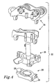
- FIGS. 3 and 4 show the tiltrotator 22 in a mounted state and in an exploded view respectively.
- the tiltrotator 22 comprises an attachment 24 (in fig. 4 alternative versions are shown for pin-on or coupler-equipped tool-bearing arm ends) for mounting the tiltrotator 22 on the arm 12 of an excavator 10, and a rotor body 26 comprising a worm gear driven by a hydraulic motor, providing unlimited rotation in a clockwise or anticlockwise direction.
- a tiltrotator or rotator may comprise any means for providing rotation, tilting or linear displacement or any combination thereof.
- the hydraulic cylinder 25 provides tilting of the rotor body 26, for example through an angle of ⁇ 40°.
- the tiltrotator 22 also comprises a coupler 28 to which a tool is attached. The structure of the coupler 28 is cast in a single piece out of ADI and has sockets for receiving mating parts of a tool 14.
- the chemical composition of the ADI coupler 28 is, for example, about 3.4-3.8 weight-% carbon, 2.3-2.7 weight-% silicon, 0.3-0.4 weight-% manganese, a maximum of 0.015 weight-% sulphur and a maximum of 0.06 weight-% phosphorus.
- alloying elements such as up to 0.8 weight-% copper, up to 2.0 weight-% nickel, and up to 0.3 weight-% molybdenum may be added to the base composition during the casting of the coupler 28, to avoid the detrimental formation of pearlite in the core due to the less rapid cooling rate from the austenitization temperature to the austempering temperature.
- the surfaces 29 of the sockets that comes into contact with mating surfaces of the tool 14 when the tiltrotator or rotator 22 is in use become work hardened and wear-resistant. It should be noted that several, if not all of the parts of a tiltrotator or rotator for coupling and/or positioning could be cast out of ADI, depending on working conditions in each specific case.
- the positioning (tilt and/or turn) functions may be excluded from the tiltrotator or rotator 22, i.e. the tiltrotator or rotator 22 may comprise only an attachment 24 for mounting it on the arm 12 of an excavator 10, and a coupler 28 for the tool 14. Furthermore, the attachment 24 and the coupler 28 may be manufactured in one piece as an integral unit.
- FIG. 5 shows a tiltrotator with a coupler 28, and a tool, namely a grapple module 25 mounted on the coupler 28 (that is hidden behind the grapple module in figure 5 ).
- the grapple module 25 is manufactured from, or contains ADI, and is arranged to grab and manipulate objects, such as pipes, logs, curb stones, without the need to replace the main tool, usually a bucket that is held by the coupler 28, with a separate grapple module.
- Figure 6 shows a rotator 26 driven by a hydraulic vane motor, providing unlimited rotation in a clockwise or anticlockwise direction, together with a pendulum braked (swing damped) attachment (link) 24, for mounting at the outermost part 12e of the arm of a material-handling machine.
- a tool such as a grapple, bucket, fork or harvesting head may be attached to the coupler 28.
- a tiltrotator or rotator may be mounted anywhere on an arm of an an earth-moving or material-handling machine, not necessarily at its end.
- Figure 7 shows a rotator 26 located between an upper attachment (link) 24 and a coupler 28 between an arm 12 of a log harvester and a harvesting head 14.
- Figure 8 shows a heat treatment cycle that is part of the method according to the invention.
- the at least one part of a tiltrotator or rotator made of unalloyed or alloyed ductile iron is heated [step di)] and held at an austenitizing temperature of between 800-1000°C for a time [step dii)] until the at least one part of a tiltrotator or rotator becomes fully austenitic and the matrix becomes saturated with carbon.
- a high quenching rate [step e)], such as 150°C/min or higher in a quenching medium and held at an austempering temperature of between 250-400°C, [step f)].
- the at least one part of a tiltrotator or rotator is cooled to room temperature [step g)].
- the tiltrotator or rotator thus made at least partially by ADI may then be mounted on an earth-moving or material-handling machine.
Landscapes
- Engineering & Computer Science (AREA)
- Chemical & Material Sciences (AREA)
- Mechanical Engineering (AREA)
- Organic Chemistry (AREA)
- Materials Engineering (AREA)
- Metallurgy (AREA)
- General Engineering & Computer Science (AREA)
- Physics & Mathematics (AREA)
- Thermal Sciences (AREA)
- Crystallography & Structural Chemistry (AREA)
- Structural Engineering (AREA)
- Civil Engineering (AREA)
- Mining & Mineral Resources (AREA)
- Heat Treatment Of Articles (AREA)
- Shovels (AREA)
Claims (9)
- Procédé pour fabriquer au moins une partie d'un tiltrotateur (22) ou d'un rotateur (26) actionné de manière mécanique ou hydraulique pour un bras (12) d'une machine de terrassement ou de manipulation de matériaux, telle qu'un excavateur, un tracteur, une moissonneuse, un porteur ou une grue (10), de sorte que le tiltrotateur (22) ou le rotateur (26) est agencé pour tenir un outil (14), tel qu'un seau, un grappin, une fourche, un rouleau vibrant ou une tête d'abattage ébranchage, et munir ladite au moins une partie dudit tiltrotateur (22) ou rotateur (26) d'une surface résistante à l'usure, ledit procédé comprenant les étapes de :a) former une coulée comprenant de la fonte ductile non alliée ou alliée,b) couler au moins une partie d'un tiltrotateur (22) ou d'un rotateur (26) à partir de ladite coulée,c) laisser refroidir ladite au moins une partie du tiltrotateur (22) ou du rotateur (26),d) austéniser ladite au moins une partie du tiltrotateur (22) ou du rotateur (26),e) tremper ladite au moins une partie du tiltrotateur (22) ou du rotateur (26),f) réaliser une trempe bainitique de ladite au moins une partie du tiltrotateur (22) ou du rotateur (26), etg) laisser refroidir ladite au moins une partie du tiltrotateur (22) ou du rotateur (26),- former au moins une surface (29) sur ladite au moins une partie du tiltrotateur (22) ou du rotateur (26) pendant le processus de coulée ou pendant l'usinage ultérieur avant traitement de trempe bainitique de la fonte ductile, et- monter ledit tiltrotateur (22) ou rotateur (26) sur ledit bras (12) d'une machine de terrassement ou de manipulation de matériaux,
caractérisé en ce que l'étape de munir ladite au moins une partie du tiltrotateur (22) ou du rotateur (26) de ladite surface résistante à l'usure est réalisée après ladite étape de monter ledit tiltrotateur (22) ou rotateur (26) sur ledit bras (12) d'une machine de temassement ou de manipulation de matériaux, de sorte que le matériau de surface (29) de ladite au moins une partie subisse une transformation en martensite lorsque ladite au moins une partie du tiltrotateur (22) ou du rotateur (26) est soumise à une force de contact élevée pendant l'utilisation, formant ainsi et régénérant ultérieurement ladite surface résistante à l'usure, de sorte qu'aucune étape de traitement supplémentaire de munir ladite au moins une partie du tiltrotateur (22) ou du rotateur (26) d'une surface résistante à l'usure ne soit par conséquent nécessaire après que ladite au moins une partie du tiltrotateur (22) ou du rotateur (26) a été coulée et soumise à une trempe bainitique et avant que ledit dispositif (22) ne soit monté sur ledit bras (12) d'une machine de terrassement ou de manipulation de matériaux. - Procédé selon la revendication 1, caractérisé en ce qu'il comprend l'étape d'usiner ladite au moins une partie du tiltrotateur (22) ou du rotateur (26) entre l'étape c) et l'étape d).
- Procédé selon l'une quelconque des revendications précédentes, caractérisé en ce qu'il comprend l'étape de couler au moins une partie du tiltrotateur (22) ou du rotateur (26) d'une seule pièce.
- Procédé selon l'une quelconque des revendications précédentes, caractérisé en ce qu'il comprend l'étape de couler ladite au moins une partie du tiltrotateur (22) ou du rotateur (26) à partir d'une fonte ductile non alliée ou alliée avec une forte teneur en silicone de 3,35 % en poids à 4,60 % en poids.
- Procédé selon la revendication 4, caractérisé en ce que la fonte ductile non alliée à forte teneur en silicone a la composition suivante en % en poids :- C 3,0-3,6- Si 3,35 - 4,60- Mn max 0,4- P max 0,05- S max 0,02- Cu max 0,1- Ni max 0,1- Mo max 0,01- reste Fe et impuretés normalement présentes.
- Procédé selon la revendication 4, caractérisé en ce que la fonte ductile alliée a la composition suivante en % en poids :- C 3,0-3,6- Si 3,35-4,60- Mn max 0,4- P max 0,05- S max 0,02- Cu max 0,8- Ni max 2,0- Mo max 0,3- reste Fe et impuretés normalement présentes.
- Procédé selon la revendication 5 ou 6, caractérisé en ce qu'il comprend l'étape d'austéniser la fonte ductile à une température d'au moins 910 °C ou d'au moins 930 °C.
- Procédé selon la revendication 7, caractérisé en ce qu'il comprend l'étape de maintenir ladite température d'austénitisation pendant une durée prédéterminée d'au moins 30 minutes pour austéniser ladite au moins une partie du tiltrotateur (22) ou du rotateur (26).
- Procédé selon l'une quelconque des revendications 4 à 8, caractérisé en ce qu'il comprend les étapes de :- former une coulée comprenant de la fonte ductile non alliée ou alliée avec une teneur en silicone de 3,35 % en poids à 4,60 % en poids,- couler au moins une partie d'un tiltrotateur (22) ou d'un rotateur (26) à partir de ladite coulée,- laisser refroidir ladite au moins une partie du tiltrotateur (22) ou du rotateur (26),- réaliser un traitement thermique d'au moins une partie de ladite au moins une partie du tiltrotateur (22) ou du rotateur (26) à une première température d'au moins 910 °C ou d'au moins 930 °C et maintenir ladite au moins une partie du tiltrotateur (22) ou du rotateur (26) à ladite température pendant une durée prédéterminée pour austéniser ladite au moins une partie du tiltrotateur (22) ou du rotateur (26),- tremper ladite au moins une partie du tiltrotateur (22) ou du rotateur (26) à une vitesse de trempe suffisante pour empêcher la formation de perlite, telle qu'au moins 150 °C/min, et- réaliser un traitement thermique de ladite au moins une partie du tiltrotateur (22) ou du rotateur (26) à une seconde température de 250-400 °C, de préférence 350-380 °C, et maintenir ladite au moins une partie du tiltrotateur (22) ou du rotateur (26) à ladite température pendant une durée prédéterminée d'au moins 30 minutes pour réaliser une trempe bainitique de ladite au moins une partie du tiltrotateur (22) ou du rotateur (26).
Applications Claiming Priority (3)
| Application Number | Priority Date | Filing Date | Title |
|---|---|---|---|
| SE0602736 | 2006-12-16 | ||
| SE0701325A SE531107C2 (sv) | 2006-12-16 | 2007-05-29 | Metod |
| PCT/SE2007/051013 WO2008076067A1 (fr) | 2006-12-16 | 2007-12-17 | Procédé de fabrication d'au moins une partie d'un dispositif destiné à un engin de terrassement ou à un engin servant à manipuler des matériaux, faisant intervenir de la fonte ductile ayant subie une trempe étagée bainitique |
Publications (3)
| Publication Number | Publication Date |
|---|---|
| EP2092088A1 EP2092088A1 (fr) | 2009-08-26 |
| EP2092088A4 EP2092088A4 (fr) | 2010-08-11 |
| EP2092088B1 true EP2092088B1 (fr) | 2016-03-23 |
Family
ID=39536559
Family Applications (2)
| Application Number | Title | Priority Date | Filing Date |
|---|---|---|---|
| EP07794212.6A Active EP2092089B1 (fr) | 2006-12-16 | 2007-09-03 | Fonte ausferritiques à graphite sphéroïdal, procédé de production de cette fonte et composant comprenant cette fonte. |
| EP07861108.4A Not-in-force EP2092088B1 (fr) | 2006-12-16 | 2007-12-17 | Procédé de fabrication d'au moins une partie d'un dispositif destiné à un engin de terrassement ou à un engin servant à manipuler des matériaux, faisant intervenir de la fonte ductile ayant subie une trempe étagée bainitique |
Family Applications Before (1)
| Application Number | Title | Priority Date | Filing Date |
|---|---|---|---|
| EP07794212.6A Active EP2092089B1 (fr) | 2006-12-16 | 2007-09-03 | Fonte ausferritiques à graphite sphéroïdal, procédé de production de cette fonte et composant comprenant cette fonte. |
Country Status (5)
| Country | Link |
|---|---|
| US (2) | US8858736B2 (fr) |
| EP (2) | EP2092089B1 (fr) |
| JP (2) | JP5368994B2 (fr) |
| SE (1) | SE531107C2 (fr) |
| WO (2) | WO2008076051A1 (fr) |
Families Citing this family (33)
| Publication number | Priority date | Publication date | Assignee | Title |
|---|---|---|---|---|
| JP5145795B2 (ja) * | 2006-07-24 | 2013-02-20 | 新日鐵住金株式会社 | 耐摩耗性および延性に優れたパーライト系レールの製造方法 |
| SE531107C2 (sv) * | 2006-12-16 | 2008-12-23 | Indexator Ab | Metod |
| US8567836B2 (en) | 2007-08-31 | 2013-10-29 | Lavalley Industries, Llc | Gripping assembly and gripping members for a grapple attachment |
| EP2201209B1 (fr) | 2007-08-31 | 2013-09-18 | LaValley Industries, LLC. | Accessoire formant grappin à utiliser dans les tiges de sondage |
| SE537181C2 (sv) | 2008-10-21 | 2015-02-24 | Svab Hydraulik Ab | Styrsystem samt förfarande för en tiltrotator |
| DE102009048273A1 (de) * | 2009-10-05 | 2011-04-07 | Bayerische Motoren Werke Aktiengesellschaft | Gusseisen-Gussteil und Verfahren zu dessen Herstellung |
| US8544562B2 (en) * | 2009-11-25 | 2013-10-01 | 1994 Weyer Family Limited Partnership | Tiltable tool assembly |
| IT1400634B1 (it) * | 2010-06-18 | 2013-06-14 | Zanardi Fonderie S P A | Procedimento per la produzione di componenti meccanici in ghisa sferoidale austemperata particolarmente resistente all'usura. |
| WO2012112863A2 (fr) | 2011-02-17 | 2012-08-23 | Lavalley Industries, Llc | Fixation à grappin dont la position est ajustable |
| US9752203B2 (en) * | 2011-10-07 | 2017-09-05 | Babasaheb Neelkanth Kalyani | Process to improve fatigue strength of micro alloy steels, forged parts made from the process and an apparatus to execute the process |
| US8524016B2 (en) * | 2012-01-03 | 2013-09-03 | General Electric Company | Method of making an austempered ductile iron article |
| BR112015001676B1 (pt) | 2012-07-27 | 2022-02-08 | Lavalley Industries, Llc | Alojamento de braço de sujeição para acessório de acoplamento |
| EP2909380A1 (fr) * | 2012-10-08 | 2015-08-26 | Rototilt Group AB | Appareil de raccordement de dispositif/d'outil et procédé associé |
| US9581103B1 (en) * | 2014-01-28 | 2017-02-28 | ZYNP International Corp. | Cylinder liner and method of forming the same |
| US10371085B2 (en) | 2014-01-28 | 2019-08-06 | ZYNP International Corp. | Cylinder liner and method of forming the same |
| US8973244B2 (en) | 2014-04-17 | 2015-03-10 | Lavalley Industries, Llc | Pipe processing tool with pipe deformation members |
| CN103952617A (zh) * | 2014-05-14 | 2014-07-30 | 扬州大学 | 新型奥贝球铁火车轮材料合金及其冶炼工艺 |
| DE102014214640A1 (de) * | 2014-07-25 | 2016-01-28 | Ford Global Technologies, Llc | Verfahren zur Herstellung eines Bauteils aus wärmebehandeltem Gusseisen |
| EP2982769A1 (fr) * | 2014-08-06 | 2016-02-10 | Indexator Group AB | Acier, procédé pour sa fabrication et composant |
| AU2016209963B2 (en) * | 2015-01-19 | 2019-11-21 | Flsmidth A/S | Interlocking wear-resistant panel system |
| AT516941B1 (de) * | 2015-04-30 | 2016-10-15 | Siemens Ag Oesterreich | Vollrad für ein Schienenfahrzeug |
| KR101984477B1 (ko) * | 2017-04-26 | 2019-05-31 | 허유진 | 작업 기계용 회전링크 |
| CN107723583B (zh) * | 2017-09-08 | 2019-05-10 | 辽宁华岳精工股份有限公司 | 一种高性能铸态奥贝球铁及其生产方法和应用 |
| KR101905493B1 (ko) | 2018-06-29 | 2018-10-08 | 노준호 | 회전형 퀵 커플러 |
| SE542672C2 (en) | 2018-09-14 | 2020-06-23 | Ausferritic Ab | Method for producing an ausferritic steel austempered during continuous cooling followed by annealing |
| SE545732C2 (en) * | 2019-02-08 | 2023-12-27 | Ausferritic Ab | Method for producing ausferritic steel and ductile iron, austempered in rapid cycles followed by baking |
| CN113123971B (zh) * | 2019-12-30 | 2023-07-11 | 丹佛斯商用压缩机公司 | 具有由固溶强化铁素体球铁制成的压缩部分的涡旋式压缩机 |
| JP7578405B2 (ja) * | 2020-03-23 | 2024-11-06 | アイシン高丘株式会社 | 差動装置 |
| KR102403912B1 (ko) * | 2020-05-04 | 2022-05-30 | 안성준 | 굴착기용 회전링크 |
| KR102491822B1 (ko) * | 2020-12-09 | 2023-01-26 | 정경래 | 틸트 링크 |
| CN113564608A (zh) * | 2021-03-02 | 2021-10-29 | 神华准格尔能源有限责任公司 | 一种柴油机整体式活塞进行整体硬化处理的方法 |
| US20240044101A1 (en) * | 2022-08-03 | 2024-02-08 | Amerequip Corp. | Cast excavator bucket |
| CN115011866A (zh) * | 2022-08-05 | 2022-09-06 | 垣曲县晋锋机械铸造有限公司 | 一种合金材料 |
Family Cites Families (40)
| Publication number | Priority date | Publication date | Assignee | Title |
|---|---|---|---|---|
| US2485760A (en) | 1947-03-22 | 1949-10-25 | Int Nickel Co | Cast ferrous alloy |
| US3549430A (en) * | 1967-11-14 | 1970-12-22 | Int Nickel Co | Bainitic ductile iron having high strength and toughness |
| US3860457A (en) * | 1972-07-12 | 1975-01-14 | Kymin Oy Kymmene Ab | A ductile iron and method of making it |
| JPS56127747A (en) * | 1980-03-08 | 1981-10-06 | Mazda Motor Corp | Vibration isolating semispherical graphite cast iron |
| WO1984002924A1 (fr) | 1983-01-24 | 1984-08-02 | Ford Werke Ag | Procede de production de parties en fer ferritique ductile de haute resistance |
| US4484953A (en) | 1983-01-24 | 1984-11-27 | Ford Motor Company | Method of making ductile cast iron with improved strength |
| JPS60110841A (ja) * | 1983-11-18 | 1985-06-17 | Toyota Motor Corp | 高Siベイナイト球状黒鉛鋳鉄 |
| JPS60262940A (ja) * | 1984-06-11 | 1985-12-26 | Toyota Motor Corp | 高ケイ素ベイナイト球状黒鉛鋳鉄 |
| SE8502514L (sv) | 1985-05-22 | 1986-11-23 | Volvo Ab | Forfarande for framstellning av ett bainitherdat segjern |
| US4666533A (en) * | 1985-09-05 | 1987-05-19 | Ford Motor Company | Hardenable cast iron and the method of making cast iron |
| JPS62112753A (ja) | 1985-11-12 | 1987-05-23 | Toyota Motor Corp | 高強度鋳鋼製品の製造方法 |
| US4737199A (en) * | 1985-12-23 | 1988-04-12 | Ford Motor Company | Machinable ductile or semiductile cast iron and method |
| JPS6456819A (en) * | 1987-08-27 | 1989-03-03 | Koshuha Chuzo Kk | Production of ductile iron having high wear resistance |
| JP2567258B2 (ja) * | 1987-10-21 | 1996-12-25 | マツダ株式会社 | 高強度、高剛性、高靱性を有する鉄系鋳物およびその製造法 |
| JPH01225745A (ja) * | 1988-03-03 | 1989-09-08 | Daikin Ind Ltd | 摺動部品 |
| US4880477A (en) * | 1988-06-14 | 1989-11-14 | Textron, Inc. | Process of making an austempered ductile iron article |
| JPH02166257A (ja) | 1988-12-20 | 1990-06-26 | Mazda Motor Corp | 球状黒鉛鋳鉄及びその製造方法 |
| US5064478A (en) * | 1989-12-04 | 1991-11-12 | Applied Process | Method and apparatus for surface austempering of cast iron parts |
| US5139579A (en) * | 1990-04-27 | 1992-08-18 | Applied Process | Method for preparing high silicon, low carbon austempered cast iron |
| US5043028A (en) * | 1990-04-27 | 1991-08-27 | Applied Process | High silicon, low carbon austemperable cast iron |
| US5082507A (en) * | 1990-10-26 | 1992-01-21 | Curry Gregory T | Austempered ductile iron gear and method of making it |
| JPH05112817A (ja) * | 1991-07-01 | 1993-05-07 | Japan Small Corp | Adi部品の熱処理方法 |
| JP2517857B2 (ja) * | 1991-09-18 | 1996-07-24 | 工業技術院長 | オ―ステンパ―ドダクタイル鋳鉄の製造方法 |
| JPH06322475A (ja) * | 1993-05-13 | 1994-11-22 | Hitachi Metals Ltd | 排気系部品及びその製造方法 |
| US5522949A (en) * | 1994-09-30 | 1996-06-04 | Industrial Materials Technology, Inc. | Class of ductile iron, and process of forming same |
| US5878897A (en) * | 1996-09-04 | 1999-03-09 | Mcconway & Torley Corporation | Slack reduced lock member for a type E raiway coupler |
| US5753055A (en) * | 1996-11-05 | 1998-05-19 | Standard Car Truck Company | Process for austempering ductile iron |
| US5837069A (en) | 1997-09-16 | 1998-11-17 | Weyburn-Bartel Inc. | Cast iron components and method of making |
| GB9814460D0 (en) * | 1998-07-04 | 1998-09-02 | Bramcote Holdings Limited | Improved drive shaft component |
| US6258180B1 (en) * | 1999-05-28 | 2001-07-10 | Waupaca Foundry, Inc. | Wear resistant ductile iron |
| JP3913935B2 (ja) * | 1999-06-21 | 2007-05-09 | 本田技研工業株式会社 | 亜共晶球状黒鉛鋳鉄 |
| GB0005740D0 (en) * | 2000-03-10 | 2000-05-03 | Downhole Products Plc | Centraliser |
| DE10129382A1 (de) * | 2001-06-20 | 2003-01-02 | Fischer Georg Fahrzeugtech | Sphärogusslegierung |
| DE10201218A1 (de) * | 2002-01-14 | 2003-07-24 | Fischer Georg Fahrzeugtech | Sphärogusslegierung |
| ITMI20021670A1 (it) * | 2002-07-26 | 2004-01-26 | Erre Vis S P A | Ghisa sferoidale particolarmente per la realizzazione di segmenti elastici di tenuta per pistoni di motori a combustione interna |
| MXPA05002433A (es) | 2002-09-04 | 2005-05-27 | Intermet Corp | Articulo de hierro colado austemperizado y capaz de maquinarse con mejoradas capacidades de maquinado resistencia a la fatiga y resistencia a la fractura bajo condiciones ambientales y metodo para fabricar el mismo. |
| AU2004216125A1 (en) * | 2003-02-27 | 2004-09-10 | Roger Cleveland Golf Company, Inc. | Golf club head of ductile or gray iron |
| EP1566454A1 (fr) * | 2004-02-10 | 2005-08-24 | Magna Drivetrain AG & Co KG | Procédé de fabrication de produits en fonte nodulaire et produits obtenus |
| JP4820562B2 (ja) * | 2004-04-05 | 2011-11-24 | 株式会社小松製作所 | Fe系耐摩耗摺動材料および摺動部材 |
| SE531107C2 (sv) * | 2006-12-16 | 2008-12-23 | Indexator Ab | Metod |
-
2007
- 2007-05-29 SE SE0701325A patent/SE531107C2/sv not_active IP Right Cessation
- 2007-09-03 JP JP2009541260A patent/JP5368994B2/ja not_active Expired - Fee Related
- 2007-09-03 EP EP07794212.6A patent/EP2092089B1/fr active Active
- 2007-09-03 US US12/519,422 patent/US8858736B2/en active Active
- 2007-09-03 WO PCT/SE2007/050607 patent/WO2008076051A1/fr not_active Ceased
- 2007-12-17 JP JP2009541266A patent/JP2010513709A/ja active Pending
- 2007-12-17 US US12/519,198 patent/US8192561B2/en not_active Expired - Fee Related
- 2007-12-17 EP EP07861108.4A patent/EP2092088B1/fr not_active Not-in-force
- 2007-12-17 WO PCT/SE2007/051013 patent/WO2008076067A1/fr not_active Ceased
Also Published As
| Publication number | Publication date |
|---|---|
| WO2008076051A1 (fr) | 2008-06-26 |
| EP2092089A1 (fr) | 2009-08-26 |
| JP2010513709A (ja) | 2010-04-30 |
| US20100111662A1 (en) | 2010-05-06 |
| JP2010513707A (ja) | 2010-04-30 |
| US8192561B2 (en) | 2012-06-05 |
| EP2092089B1 (fr) | 2016-02-17 |
| JP5368994B2 (ja) | 2013-12-18 |
| SE531107E5 (fr) | 2011-04-26 |
| US8858736B2 (en) | 2014-10-14 |
| EP2092088A1 (fr) | 2009-08-26 |
| US20100006189A1 (en) | 2010-01-14 |
| WO2008076067A1 (fr) | 2008-06-26 |
| SE531107C2 (sv) | 2008-12-23 |
| SE0701325L (sv) | 2008-06-17 |
| EP2092088A4 (fr) | 2010-08-11 |
| EP2092089A4 (fr) | 2010-08-11 |
Similar Documents
| Publication | Publication Date | Title |
|---|---|---|
| EP2092088B1 (fr) | Procédé de fabrication d'au moins une partie d'un dispositif destiné à un engin de terrassement ou à un engin servant à manipuler des matériaux, faisant intervenir de la fonte ductile ayant subie une trempe étagée bainitique | |
| JP4812220B2 (ja) | 高硬度高靭性鋼 | |
| Chen et al. | Molybdenum alloying in cast iron and steel | |
| CN104831189B (zh) | Hb600级非调质耐磨钢板及其制造方法 | |
| Subramanyam et al. | Austenitic manganese steels | |
| JP2005281856A (ja) | Fe系シール摺動部材およびその製造方法 | |
| JP2010513709A5 (fr) | ||
| KR101704821B1 (ko) | 내마모성과 내충격성이 향상된 건설기계용 버켓 투스 | |
| JP2009001910A (ja) | 高硬度高靭性鋼 | |
| JPH11350066A (ja) | 被削性に優れた熱間鍛造鋼部品の製造方法及びその部品並びにそれに用いる熱間圧延鋼材 | |
| US8480820B2 (en) | Ferrous abrasion resistant sliding materials and sliding members | |
| CN105002430A (zh) | Hb360级复相组织耐磨钢板及其生产方法 | |
| CN104789881A (zh) | 一种高强度高韧性耐磨钢板的生产方法 | |
| JP4084462B2 (ja) | 快削熱間加工鋼材およびその製造方法 | |
| EP2294231B1 (fr) | Traitement thermique de trempe étagée bainitique pendant pressage isostatique | |
| KR100415626B1 (ko) | 경화능이 우수한 고강도 내마모강 | |
| JP2008280618A (ja) | 高硬度高靭性鋼 | |
| JP3764274B2 (ja) | 快削熱間加工鋼材及び粗形材、これらの製造方法並びに快削熱間加工製品及びその製造方法 | |
| Nofal | The current status of the metallurgy and processing of austempered ductile iron (ADI) | |
| JP2024055225A (ja) | 建設機械用部品 | |
| KR20120053618A (ko) | 내마모성과 내충격성이 향상된 건설기계의 브레이커용 치즐 | |
| EP4663805A1 (fr) | Acier moulé au chrome avec résistance à l'usure améliorée | |
| JPH11293387A (ja) | 快削性に優れた熱間加工鋼材及び製品並びにそれらの製造方法 | |
| KR101211798B1 (ko) | 내마모 기계부품의 제조방법 | |
| JP3879251B2 (ja) | 強度と靱性に優れた表面硬化部品の製造方法 |
Legal Events
| Date | Code | Title | Description |
|---|---|---|---|
| PUAI | Public reference made under article 153(3) epc to a published international application that has entered the european phase |
Free format text: ORIGINAL CODE: 0009012 |
|
| 17P | Request for examination filed |
Effective date: 20090528 |
|
| AK | Designated contracting states |
Kind code of ref document: A1 Designated state(s): AT BE BG CH CY CZ DE DK EE ES FI FR GB GR HU IE IS IT LI LT LU LV MC MT NL PL PT RO SE SI SK TR |
|
| DAX | Request for extension of the european patent (deleted) | ||
| A4 | Supplementary search report drawn up and despatched |
Effective date: 20100714 |
|
| 17Q | First examination report despatched |
Effective date: 20110413 |
|
| RAP1 | Party data changed (applicant data changed or rights of an application transferred) |
Owner name: INDEXATOR GROUP AB |
|
| APBK | Appeal reference recorded |
Free format text: ORIGINAL CODE: EPIDOSNREFNE |
|
| APBN | Date of receipt of notice of appeal recorded |
Free format text: ORIGINAL CODE: EPIDOSNNOA2E |
|
| APBR | Date of receipt of statement of grounds of appeal recorded |
Free format text: ORIGINAL CODE: EPIDOSNNOA3E |
|
| APAF | Appeal reference modified |
Free format text: ORIGINAL CODE: EPIDOSCREFNE |
|
| APBT | Appeal procedure closed |
Free format text: ORIGINAL CODE: EPIDOSNNOA9E |
|
| GRAP | Despatch of communication of intention to grant a patent |
Free format text: ORIGINAL CODE: EPIDOSNIGR1 |
|
| INTG | Intention to grant announced |
Effective date: 20150929 |
|
| GRAS | Grant fee paid |
Free format text: ORIGINAL CODE: EPIDOSNIGR3 |
|
| GRAA | (expected) grant |
Free format text: ORIGINAL CODE: 0009210 |
|
| AK | Designated contracting states |
Kind code of ref document: B1 Designated state(s): AT BE BG CH CY CZ DE DK EE ES FI FR GB GR HU IE IS IT LI LT LU LV MC MT NL PL PT RO SE SI SK TR |
|
| REG | Reference to a national code |
Ref country code: GB Ref legal event code: FG4D |
|
| REG | Reference to a national code |
Ref country code: CH Ref legal event code: EP |
|
| REG | Reference to a national code |
Ref country code: AT Ref legal event code: REF Ref document number: 783227 Country of ref document: AT Kind code of ref document: T Effective date: 20160415 |
|
| REG | Reference to a national code |
Ref country code: IE Ref legal event code: FG4D |
|
| REG | Reference to a national code |
Ref country code: DE Ref legal event code: R096 Ref document number: 602007045473 Country of ref document: DE |
|
| REG | Reference to a national code |
Ref country code: SE Ref legal event code: TRGR |
|
| REG | Reference to a national code |
Ref country code: LT Ref legal event code: MG4D |
|
| REG | Reference to a national code |
Ref country code: NL Ref legal event code: MP Effective date: 20160323 |
|
| PG25 | Lapsed in a contracting state [announced via postgrant information from national office to epo] |
Ref country code: FI Free format text: LAPSE BECAUSE OF FAILURE TO SUBMIT A TRANSLATION OF THE DESCRIPTION OR TO PAY THE FEE WITHIN THE PRESCRIBED TIME-LIMIT Effective date: 20160323 Ref country code: GR Free format text: LAPSE BECAUSE OF FAILURE TO SUBMIT A TRANSLATION OF THE DESCRIPTION OR TO PAY THE FEE WITHIN THE PRESCRIBED TIME-LIMIT Effective date: 20160624 |
|
| REG | Reference to a national code |
Ref country code: AT Ref legal event code: MK05 Ref document number: 783227 Country of ref document: AT Kind code of ref document: T Effective date: 20160323 |
|
| PG25 | Lapsed in a contracting state [announced via postgrant information from national office to epo] |
Ref country code: LT Free format text: LAPSE BECAUSE OF FAILURE TO SUBMIT A TRANSLATION OF THE DESCRIPTION OR TO PAY THE FEE WITHIN THE PRESCRIBED TIME-LIMIT Effective date: 20160323 Ref country code: LV Free format text: LAPSE BECAUSE OF FAILURE TO SUBMIT A TRANSLATION OF THE DESCRIPTION OR TO PAY THE FEE WITHIN THE PRESCRIBED TIME-LIMIT Effective date: 20160323 Ref country code: NL Free format text: LAPSE BECAUSE OF FAILURE TO SUBMIT A TRANSLATION OF THE DESCRIPTION OR TO PAY THE FEE WITHIN THE PRESCRIBED TIME-LIMIT Effective date: 20160323 |
|
| PG25 | Lapsed in a contracting state [announced via postgrant information from national office to epo] |
Ref country code: IS Free format text: LAPSE BECAUSE OF FAILURE TO SUBMIT A TRANSLATION OF THE DESCRIPTION OR TO PAY THE FEE WITHIN THE PRESCRIBED TIME-LIMIT Effective date: 20160723 Ref country code: EE Free format text: LAPSE BECAUSE OF FAILURE TO SUBMIT A TRANSLATION OF THE DESCRIPTION OR TO PAY THE FEE WITHIN THE PRESCRIBED TIME-LIMIT Effective date: 20160323 Ref country code: PL Free format text: LAPSE BECAUSE OF FAILURE TO SUBMIT A TRANSLATION OF THE DESCRIPTION OR TO PAY THE FEE WITHIN THE PRESCRIBED TIME-LIMIT Effective date: 20160323 |
|
| PG25 | Lapsed in a contracting state [announced via postgrant information from national office to epo] |
Ref country code: ES Free format text: LAPSE BECAUSE OF FAILURE TO SUBMIT A TRANSLATION OF THE DESCRIPTION OR TO PAY THE FEE WITHIN THE PRESCRIBED TIME-LIMIT Effective date: 20160323 Ref country code: AT Free format text: LAPSE BECAUSE OF FAILURE TO SUBMIT A TRANSLATION OF THE DESCRIPTION OR TO PAY THE FEE WITHIN THE PRESCRIBED TIME-LIMIT Effective date: 20160323 Ref country code: RO Free format text: LAPSE BECAUSE OF FAILURE TO SUBMIT A TRANSLATION OF THE DESCRIPTION OR TO PAY THE FEE WITHIN THE PRESCRIBED TIME-LIMIT Effective date: 20160323 Ref country code: SK Free format text: LAPSE BECAUSE OF FAILURE TO SUBMIT A TRANSLATION OF THE DESCRIPTION OR TO PAY THE FEE WITHIN THE PRESCRIBED TIME-LIMIT Effective date: 20160323 Ref country code: PT Free format text: LAPSE BECAUSE OF FAILURE TO SUBMIT A TRANSLATION OF THE DESCRIPTION OR TO PAY THE FEE WITHIN THE PRESCRIBED TIME-LIMIT Effective date: 20160725 Ref country code: CZ Free format text: LAPSE BECAUSE OF FAILURE TO SUBMIT A TRANSLATION OF THE DESCRIPTION OR TO PAY THE FEE WITHIN THE PRESCRIBED TIME-LIMIT Effective date: 20160323 |
|
| REG | Reference to a national code |
Ref country code: FR Ref legal event code: PLFP Year of fee payment: 10 |
|
| PG25 | Lapsed in a contracting state [announced via postgrant information from national office to epo] |
Ref country code: BE Free format text: LAPSE BECAUSE OF FAILURE TO SUBMIT A TRANSLATION OF THE DESCRIPTION OR TO PAY THE FEE WITHIN THE PRESCRIBED TIME-LIMIT Effective date: 20160323 |
|
| REG | Reference to a national code |
Ref country code: DE Ref legal event code: R097 Ref document number: 602007045473 Country of ref document: DE |
|
| PLBE | No opposition filed within time limit |
Free format text: ORIGINAL CODE: 0009261 |
|
| STAA | Information on the status of an ep patent application or granted ep patent |
Free format text: STATUS: NO OPPOSITION FILED WITHIN TIME LIMIT |
|
| PG25 | Lapsed in a contracting state [announced via postgrant information from national office to epo] |
Ref country code: DK Free format text: LAPSE BECAUSE OF FAILURE TO SUBMIT A TRANSLATION OF THE DESCRIPTION OR TO PAY THE FEE WITHIN THE PRESCRIBED TIME-LIMIT Effective date: 20160323 |
|
| PG25 | Lapsed in a contracting state [announced via postgrant information from national office to epo] |
Ref country code: BG Free format text: LAPSE BECAUSE OF FAILURE TO SUBMIT A TRANSLATION OF THE DESCRIPTION OR TO PAY THE FEE WITHIN THE PRESCRIBED TIME-LIMIT Effective date: 20160623 |
|
| 26N | No opposition filed |
Effective date: 20170102 |
|
| PG25 | Lapsed in a contracting state [announced via postgrant information from national office to epo] |
Ref country code: SI Free format text: LAPSE BECAUSE OF FAILURE TO SUBMIT A TRANSLATION OF THE DESCRIPTION OR TO PAY THE FEE WITHIN THE PRESCRIBED TIME-LIMIT Effective date: 20160323 |
|
| REG | Reference to a national code |
Ref country code: CH Ref legal event code: PL |
|
| PG25 | Lapsed in a contracting state [announced via postgrant information from national office to epo] |
Ref country code: MC Free format text: LAPSE BECAUSE OF FAILURE TO SUBMIT A TRANSLATION OF THE DESCRIPTION OR TO PAY THE FEE WITHIN THE PRESCRIBED TIME-LIMIT Effective date: 20160323 |
|
| REG | Reference to a national code |
Ref country code: IE Ref legal event code: MM4A |
|
| PG25 | Lapsed in a contracting state [announced via postgrant information from national office to epo] |
Ref country code: LU Free format text: LAPSE BECAUSE OF NON-PAYMENT OF DUE FEES Effective date: 20161217 Ref country code: CH Free format text: LAPSE BECAUSE OF NON-PAYMENT OF DUE FEES Effective date: 20161231 Ref country code: LI Free format text: LAPSE BECAUSE OF NON-PAYMENT OF DUE FEES Effective date: 20161231 |
|
| PG25 | Lapsed in a contracting state [announced via postgrant information from national office to epo] |
Ref country code: IE Free format text: LAPSE BECAUSE OF NON-PAYMENT OF DUE FEES Effective date: 20161217 |
|
| REG | Reference to a national code |
Ref country code: FR Ref legal event code: PLFP Year of fee payment: 11 |
|
| PG25 | Lapsed in a contracting state [announced via postgrant information from national office to epo] |
Ref country code: CY Free format text: LAPSE BECAUSE OF FAILURE TO SUBMIT A TRANSLATION OF THE DESCRIPTION OR TO PAY THE FEE WITHIN THE PRESCRIBED TIME-LIMIT Effective date: 20160323 Ref country code: HU Free format text: LAPSE BECAUSE OF FAILURE TO SUBMIT A TRANSLATION OF THE DESCRIPTION OR TO PAY THE FEE WITHIN THE PRESCRIBED TIME-LIMIT; INVALID AB INITIO Effective date: 20071217 |
|
| PG25 | Lapsed in a contracting state [announced via postgrant information from national office to epo] |
Ref country code: TR Free format text: LAPSE BECAUSE OF FAILURE TO SUBMIT A TRANSLATION OF THE DESCRIPTION OR TO PAY THE FEE WITHIN THE PRESCRIBED TIME-LIMIT Effective date: 20160323 |
|
| PG25 | Lapsed in a contracting state [announced via postgrant information from national office to epo] |
Ref country code: MT Free format text: LAPSE BECAUSE OF NON-PAYMENT OF DUE FEES Effective date: 20161217 |
|
| PGFP | Annual fee paid to national office [announced via postgrant information from national office to epo] |
Ref country code: GB Payment date: 20231213 Year of fee payment: 17 |
|
| PGFP | Annual fee paid to national office [announced via postgrant information from national office to epo] |
Ref country code: SE Payment date: 20231220 Year of fee payment: 17 Ref country code: IT Payment date: 20231211 Year of fee payment: 17 Ref country code: FR Payment date: 20231222 Year of fee payment: 17 |
|
| PGFP | Annual fee paid to national office [announced via postgrant information from national office to epo] |
Ref country code: DE Payment date: 20240112 Year of fee payment: 17 |
|
| REG | Reference to a national code |
Ref country code: DE Ref legal event code: R119 Ref document number: 602007045473 Country of ref document: DE |
|
| REG | Reference to a national code |
Ref country code: SE Ref legal event code: EUG |
|
| GBPC | Gb: european patent ceased through non-payment of renewal fee |
Effective date: 20241217 |
|
| PG25 | Lapsed in a contracting state [announced via postgrant information from national office to epo] |
Ref country code: DE Free format text: LAPSE BECAUSE OF NON-PAYMENT OF DUE FEES Effective date: 20250701 |
|
| PG25 | Lapsed in a contracting state [announced via postgrant information from national office to epo] |
Ref country code: IT Free format text: LAPSE BECAUSE OF NON-PAYMENT OF DUE FEES Effective date: 20241217 |
|
| PG25 | Lapsed in a contracting state [announced via postgrant information from national office to epo] |
Ref country code: GB Free format text: LAPSE BECAUSE OF NON-PAYMENT OF DUE FEES Effective date: 20241217 |
|
| PG25 | Lapsed in a contracting state [announced via postgrant information from national office to epo] |
Ref country code: FR Free format text: LAPSE BECAUSE OF NON-PAYMENT OF DUE FEES Effective date: 20241231 |