EP2092368B1 - Procédé et dispositif pour la reconnaissance de précipitation à l'aide de radiodétection - Google Patents
Procédé et dispositif pour la reconnaissance de précipitation à l'aide de radiodétection Download PDFInfo
- Publication number
- EP2092368B1 EP2092368B1 EP07803522A EP07803522A EP2092368B1 EP 2092368 B1 EP2092368 B1 EP 2092368B1 EP 07803522 A EP07803522 A EP 07803522A EP 07803522 A EP07803522 A EP 07803522A EP 2092368 B1 EP2092368 B1 EP 2092368B1
- Authority
- EP
- European Patent Office
- Prior art keywords
- radar
- precipitation
- mean
- power spectral
- scattered
- Prior art date
- Legal status (The legal status is an assumption and is not a legal conclusion. Google has not performed a legal analysis and makes no representation as to the accuracy of the status listed.)
- Not-in-force
Links
- 238000001556 precipitation Methods 0.000 title claims abstract description 38
- 238000000034 method Methods 0.000 title claims abstract description 36
- 230000005855 radiation Effects 0.000 claims description 30
- 230000003595 spectral effect Effects 0.000 claims description 23
- 238000004590 computer program Methods 0.000 claims description 12
- 238000001514 detection method Methods 0.000 claims description 8
- 238000011156 evaluation Methods 0.000 claims description 4
- 230000005540 biological transmission Effects 0.000 claims description 3
- 230000010354 integration Effects 0.000 claims description 3
- 238000004458 analytical method Methods 0.000 claims description 2
- 238000013500 data storage Methods 0.000 claims 1
- 239000012585 homogenous medium Substances 0.000 abstract 1
- 238000001228 spectrum Methods 0.000 description 19
- 239000002244 precipitate Substances 0.000 description 11
- 238000013459 approach Methods 0.000 description 6
- 230000008901 benefit Effects 0.000 description 4
- 238000002310 reflectometry Methods 0.000 description 4
- 230000008859 change Effects 0.000 description 3
- 230000008054 signal transmission Effects 0.000 description 3
- 230000002238 attenuated effect Effects 0.000 description 2
- 230000000694 effects Effects 0.000 description 2
- 238000005259 measurement Methods 0.000 description 2
- 239000002245 particle Substances 0.000 description 2
- 238000003491 array Methods 0.000 description 1
- 239000002775 capsule Substances 0.000 description 1
- 230000015556 catabolic process Effects 0.000 description 1
- 238000006243 chemical reaction Methods 0.000 description 1
- 238000006731 degradation reaction Methods 0.000 description 1
- 238000011161 development Methods 0.000 description 1
- 238000010586 diagram Methods 0.000 description 1
- 230000009977 dual effect Effects 0.000 description 1
- 230000005670 electromagnetic radiation Effects 0.000 description 1
- 238000002955 isolation Methods 0.000 description 1
- 238000012986 modification Methods 0.000 description 1
- 230000004048 modification Effects 0.000 description 1
- 230000002093 peripheral effect Effects 0.000 description 1
- 238000012545 processing Methods 0.000 description 1
- 230000009467 reduction Effects 0.000 description 1
- 239000007787 solid Substances 0.000 description 1
- 239000000126 substance Substances 0.000 description 1
Images

Classifications
-
- G—PHYSICS
- G01—MEASURING; TESTING
- G01S—RADIO DIRECTION-FINDING; RADIO NAVIGATION; DETERMINING DISTANCE OR VELOCITY BY USE OF RADIO WAVES; LOCATING OR PRESENCE-DETECTING BY USE OF THE REFLECTION OR RERADIATION OF RADIO WAVES; ANALOGOUS ARRANGEMENTS USING OTHER WAVES
- G01S13/00—Systems using the reflection or reradiation of radio waves, e.g. radar systems; Analogous systems using reflection or reradiation of waves whose nature or wavelength is irrelevant or unspecified
- G01S13/88—Radar or analogous systems specially adapted for specific applications
- G01S13/95—Radar or analogous systems specially adapted for specific applications for meteorological use
- G01S13/956—Radar or analogous systems specially adapted for specific applications for meteorological use mounted on ship or other platform
-
- G—PHYSICS
- G01—MEASURING; TESTING
- G01S—RADIO DIRECTION-FINDING; RADIO NAVIGATION; DETERMINING DISTANCE OR VELOCITY BY USE OF RADIO WAVES; LOCATING OR PRESENCE-DETECTING BY USE OF THE REFLECTION OR RERADIATION OF RADIO WAVES; ANALOGOUS ARRANGEMENTS USING OTHER WAVES
- G01S7/00—Details of systems according to groups G01S13/00, G01S15/00, G01S17/00
- G01S7/02—Details of systems according to groups G01S13/00, G01S15/00, G01S17/00 of systems according to group G01S13/00
- G01S7/41—Details of systems according to groups G01S13/00, G01S15/00, G01S17/00 of systems according to group G01S13/00 using analysis of echo signal for target characterisation; Target signature; Target cross-section
- G01S7/411—Identification of targets based on measurements of radar reflectivity
-
- G—PHYSICS
- G01—MEASURING; TESTING
- G01S—RADIO DIRECTION-FINDING; RADIO NAVIGATION; DETERMINING DISTANCE OR VELOCITY BY USE OF RADIO WAVES; LOCATING OR PRESENCE-DETECTING BY USE OF THE REFLECTION OR RERADIATION OF RADIO WAVES; ANALOGOUS ARRANGEMENTS USING OTHER WAVES
- G01S13/00—Systems using the reflection or reradiation of radio waves, e.g. radar systems; Analogous systems using reflection or reradiation of waves whose nature or wavelength is irrelevant or unspecified
- G01S13/87—Combinations of radar systems, e.g. primary radar and secondary radar
-
- G—PHYSICS
- G01—MEASURING; TESTING
- G01S—RADIO DIRECTION-FINDING; RADIO NAVIGATION; DETERMINING DISTANCE OR VELOCITY BY USE OF RADIO WAVES; LOCATING OR PRESENCE-DETECTING BY USE OF THE REFLECTION OR RERADIATION OF RADIO WAVES; ANALOGOUS ARRANGEMENTS USING OTHER WAVES
- G01S13/00—Systems using the reflection or reradiation of radio waves, e.g. radar systems; Analogous systems using reflection or reradiation of waves whose nature or wavelength is irrelevant or unspecified
- G01S13/88—Radar or analogous systems specially adapted for specific applications
- G01S13/93—Radar or analogous systems specially adapted for specific applications for anti-collision purposes
- G01S13/931—Radar or analogous systems specially adapted for specific applications for anti-collision purposes of land vehicles
-
- G—PHYSICS
- G01—MEASURING; TESTING
- G01S—RADIO DIRECTION-FINDING; RADIO NAVIGATION; DETERMINING DISTANCE OR VELOCITY BY USE OF RADIO WAVES; LOCATING OR PRESENCE-DETECTING BY USE OF THE REFLECTION OR RERADIATION OF RADIO WAVES; ANALOGOUS ARRANGEMENTS USING OTHER WAVES
- G01S13/00—Systems using the reflection or reradiation of radio waves, e.g. radar systems; Analogous systems using reflection or reradiation of waves whose nature or wavelength is irrelevant or unspecified
- G01S13/88—Radar or analogous systems specially adapted for specific applications
- G01S13/93—Radar or analogous systems specially adapted for specific applications for anti-collision purposes
- G01S13/931—Radar or analogous systems specially adapted for specific applications for anti-collision purposes of land vehicles
- G01S2013/9327—Sensor installation details
- G01S2013/93271—Sensor installation details in the front of the vehicles
-
- Y—GENERAL TAGGING OF NEW TECHNOLOGICAL DEVELOPMENTS; GENERAL TAGGING OF CROSS-SECTIONAL TECHNOLOGIES SPANNING OVER SEVERAL SECTIONS OF THE IPC; TECHNICAL SUBJECTS COVERED BY FORMER USPC CROSS-REFERENCE ART COLLECTIONS [XRACs] AND DIGESTS
- Y02—TECHNOLOGIES OR APPLICATIONS FOR MITIGATION OR ADAPTATION AGAINST CLIMATE CHANGE
- Y02A—TECHNOLOGIES FOR ADAPTATION TO CLIMATE CHANGE
- Y02A90/00—Technologies having an indirect contribution to adaptation to climate change
- Y02A90/10—Information and communication technologies [ICT] supporting adaptation to climate change, e.g. for weather forecasting or climate simulation
Definitions
- the invention relates to a method for detecting precipitation in a radar-detected area according to claim 1, an apparatus for carrying out this method, a computer program and a computer program product.
- Precipitation such as rain, hail, fog or snowfall
- the precipitation intensity can be determined by means of radar, in that a directional antenna radiates pulse-shaped electromagnetic radiation in the microwave range.
- a radar system can be used that emits radar beams with a wavelength of about 3 to 10 cm. If the radiation in the atmosphere hits a particle whose diameter is greater than about 0.2 mm, the radiation is reflected by it. The wavelength of the radiation does not change. Part of this radiation is picked up by a receiver of the radar and the reflectivity is measured. From the reflectivity, the precipitation intensity can be calculated if certain assumptions are made about the particle or droplet size distribution of the precipitate. A conversion then takes place with a so-called Z-R relationship, where Z stands for reflectivity and R for the precipitation intensity.
- the WO 1993002370 A1 describes a method for detecting rain. Several radar signals are emitted. Backscattered signals are received, to create a Doppler spectrum. A reduced amplitude in the Doppler spectrum, especially in the peripheral regions of the spectrum, indicates rainfall.
- the EP 1229348 A1 describes a system for detecting rain or hail by means of a weather radar. Different standard deviation and return radiation intensity maps are combined with each other.
- the JP 07248830 A describes a device for correcting a calculated rainfall intensity in the context of a radar.
- the JP 10048333 A describes a radar with which snowfall or rain can be detected by receiving a reflected signal and measuring its level.
- a method for detecting precipitation by means of two radar beams for aircraft is known from US 5,028,929 known.
- at least two radar signals are transmitted, wherein the sizes of backscattered radar signals are determined.
- a determination of the presence of precipitation is made by comparing the thus determined attenuation characteristics of the two backscattered radar signals.
- the present invention proposes a method for detecting precipitation in a region covered by radar beams, furthermore a device which uses this method, and finally a corresponding computer program and a computer program product according to the independent patent claims.
- Advantageous embodiments emerge from the respective subclaims and the following description.
- a first average power of a first backscattered radar signal and a second average power of a second backscattered radar signal are determined.
- a presence of precipitate is determined by a comparison of the mean powers with each other
- a determination of the correspondence of the average powers takes place according to the invention taking into account at least one weighting factor, wherein the at least one weighting factor is designed to compensate for different radar antenna characteristics.
- the average powers can be compared even if the underlying radar signals originate from differently designed radar transmitters. This increases the flexibility of the method according to the invention.
- a correspondence of the mean powers is determined by means of correlation of the respectively determined average powers.
- a determination of a further average power of a further backscattered radar signal takes place.
- the evaluation of more than two backscattered radar signals increases the accuracy of the detection of precipitation.
- the backscattered radar signals may be reflections of radar signals emitted by adjacent radar transmitters.
- the mean powers are determined in each case for an object-free section of the detected area.
- a spectral power density for each backscattered radar signal is detected and superimposed on the object-free section.
- the object-free section can be determined by an analysis of the spectral power densities of the backscattered radar signals.
- the object-free section corresponds to a common subarea of the spectral power densities in which none of the spectral power densities has a peak that protrudes above a noise floor of the respective spectral power density.
- a density of the precipitate or a radar signal attenuation can be determined. This can be done by evaluating an increase in the noise floor of at least one of the spectral power densities.
- the precipitation can be, for example, rain, snow, fog or hail.
- a main direction of movement of the precipitate may be orthogonal to the Be radar beams.
- the precipitate according to the inventive approach can be recognized without evaluation of a Doppler effect.
- a long range radar FMCW radar transmitter is used to generate partially overlapping or adjacent radar beams.
- the backscattered radar signals can each be assigned to a radiation cone.
- Called FMCW radar (engl. F requency M odulated C ontinuous W ave), also modulated continuous wave radar, a radar signal with constantly changing frequency. The frequency either increases linearly to drop abruptly to the initial value at a certain frequency (sawtooth pattern), or it can alternately rise and fall at a constant rate of change.
- By such a linear change of the frequency and a simultaneous continuous transmission it is possible to determine apart from the differential speed between the transmitter and the object at the same time their absolute distance from each other.
- a device according to the invention performs all the steps of the method according to the invention.
- the computer program with program code means according to the invention is designed to perform all the steps of the method according to the invention when this computer program is carried out on a computer or a corresponding computing unit, in particular a device according to the invention.
- the computer program product according to the invention with program code means, which are stored on a computer-readable data carrier, is provided for carrying out the method according to the invention when this computer program is carried out on a computer or a corresponding computing unit, in particular a device according to the invention.
- the present invention is based on the recognition that radar sensors are degraded differently by the occurrence of precipitation in the signal transmission medium, depending on the operating frequency.
- the precipitation can be, for example, rain or snowfall.
- the effect of degradation occurs especially at higher frequencies, such as those used in automotive radar sensors and may cause different Degrationsgrade the radar signal depending on the precipitation intensity.
- Long Range Radar uses more than two radiation beams or antenna beams to locate objects in a traffic scenario. Provided receivers or sensors will receive the same intensity 1 in road traffic only if the radiated radar signal is backscattered by a radar cell homogeneously or uniformly filling object, such as rain.
- the radar cell corresponds to the field of view or fietd-of-view of the radar.
- the approach of the invention can be used for a variety of applications.
- the present invention enables detection of precipitation occurrence in the radar signal transmission medium. Furthermore, an intensity of the precipitate can be determined and a radar transmitter performance loss can be estimated.
- the present invention can be used to switch the system, e.g. a modulation system to which the current signal transmission medium is used. That is, it is conceivable, for example, to vary the power of the transmitted signals as a function of a determined precipitation.
- a further advantage of the approach according to the invention is that the method according to the invention can be applied in part without modification to existing automotive radar transmitters which produce at least two radiation cones. Future radar transmitters or systems may be optimized to take advantage of the benefits of the present invention.
- the approach according to the invention is suitable as a signal source for safety-relevant systems in vehicles.
- Fig.1 shows an application of a multi-beam automotive radar system in traffic.
- a vehicle 1 also called a radar vehicle, is equipped with a long range radar system (LRR).
- the radar system includes at least one transmitter, at least one receiver, and processing means, such as a microprocessor for evaluating returned radiation received by the receiver.
- Transmitter and receiver are expediently implemented as an antenna, transmitting and receiving functions.
- the vehicle 1 moves on a road which may be delimited by boundaries, for example in the form of a guard rail. On the road move further vehicles 3, which can be detected by the radar of the vehicle 1.
- the radar of the vehicle 1 emits a plurality of radar cones or antenna beams 4.
- An area detected by the antenna beams 4 is interspersed with precipitation, in this case Rain 5.
- the main direction of movement of the precipitate is orthogonal to the radar beams.
- the radar beams are emitted in the horizontal direction.
- the rain falls in a vertical direction.
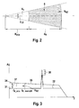
- Fig. 2 shows a schematic representation of raindrops in a monostatic radar cell.
- the radar cell may be an area that is one of those in Fig. 1 shown radiation cone 4 is detected.
- the monostatic radar cell is based on a radar located at the pointed end of the radiation cone.
- the angles ⁇ and ⁇ indicate a horizontal or vertical antenna opening angle.
- the radar cell can be divided into two sections.
- a first section V 1 starts from the radar and is limited by the radius R min .
- the second section V RZ adjoins the first section, has a length of d R and is thus bounded by the radius R min + d R.
- the second section V RZ of the radar cell is interspersed with rain 5 and thus represents a rain cell.
- Within the rain cell apart from precipitation in the form of rain 5, there are no inhomogeneous objects, such as vehicles 3.
- a radar wave is emitted by a transmitter located on the vehicle 1, reflected on the object, for example a vehicle 3, and picked up again by a receiver assigned to the transmitter.
- the transit times and Doppler shifts that occur are used in radar sensors to determine the distance and relative speed of the object.
- several radiation cones 4 are used to localize objects to be detected in the traffic scenario.
- an object for example for an FMCW radar system, results in a peak in the spectrum, which is detected simultaneously by two neighboring radiation cones.
- the angle to the object can be determined.
- Figure 3 shows a signal spectrum using the example of the FMCW radar.
- the frequency f is plotted on the horizontal axis and the amplitude spectrum A of a backscattered signal (echo) on the vertical axis.
- a first spectrum 31 shows an application in which a radar signal is reflected by a fixed object.
- the object may be, for example, one of the in Fig. 1 shown vehicles 3 act.
- the radar signal is not attenuated by precipitation.
- the first spectrum 31 therefore has a low noise floor 32 and a high peak.
- the peak in the form of a peak shape, which clearly protrudes from the noise floor 32, will be caused by reflection of the radar signal on the object.
- a second spectrum 34 shows an application in which the radar signal in turn is reflected by the object.
- the radar signal is damped by precipitation.
- the second spectrum 34 therefore has a high background noise 35.
- the noise floor 35 is significantly higher than that of the first spectrum 31.
- the second spectrum 34 has a lower peak than the first spectrum 31.
- the increase of the background noise by precipitation is indicated by the reference numeral 37 and an object peak reduction by the reference numeral 38.
- Signals reflected by a substance uniformly filling the radar cell, such as precipitate, will not give a peak in the spectrum of the FMCW radar. Instead, results in a broad frequency range distributed signal power, which significantly raises the noise floor 35 of the second spectrum 34.
- This signal power is used by all who, for example, in Fig. 1 reflected radiation cone 4 back and can be calculated for an object-free section of the radar cell from the measured spectral power density. This is done, for example, according to the principle of multiple scattering of the first order of narrow radiation cones (narrow-beam first order multiple scattering).
- the region bounded by the frequencies f R_min and f R min + d R therefore indicates an average rain backscatter from the rain cell 5.
- the average power backscattered by the rain is calculated by integrating the spectral power density measured with LRR in the section f R min + d R to f R min + d R + f dR of the radar cell according to the multiple scattering principle mentioned. From this, the rain intensity can be determined via the backscatter cross section of the rain and thus the radar signal attenuation or the LRR performance loss.
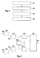
- FIG. 12 shows a flowchart of a method for detecting precipitation in a radar-detected area according to a preferred embodiment of the present invention.
- a first step 401 at least two radiation capsules which are not or only partially overlap are emitted by means of at least one corresponding transmitter (antenna).
- a first average power of a first backscattered radar signal is determined.
- a second average power of a second backscattered radar signal is determined.
- a determination and optionally an indication of the presence of precipitation takes place with a correspondence of the average powers of the two backscattered signals.
- the area covered in FIG Fig. 1 act shown area which is covered by the radiation cone 4.
- the precipitate may be inhomogeneity of the area detected by radar beams, except for existing solid objects which are inhomogeneity with respect to the detected area, for example in the form of in Fig.1 shown vehicles 3, evenly.
- radar beams can partially penetrate the precipitation.
- the method according to the invention can have one or more further steps of determining one or more further average powers.
- the other average powers are determined from the further backscattered radar signals.
- the backscattered radar signals may be generated by reflection from radar signals emitted by adjacent radar transmitters (antennas).
- the radar signals are emitted by radar transmitters or antennas which are arranged adjacent to a front side of the vehicle 1. It is also conceivable to cover the entire area covered by the radiation cone 4 by means of a single antenna, which is embodied correspondingly pivotable between the transmission of individual radiation cones.
- the average powers can be adapted to each other.
- a determination of the correspondence of the mean powers I can then take place taking into account at least one weighting factor, wherein the at least one weighting factor is designed to compensate for different radar antenna characteristics.
- the average powers are each determined for an object-free portion of the detected area.
- the steps of determining may each comprise a step of detecting a spectral power density of the backscattered radar signal and a step of integrating the spectral power density, respectively over the non-object portion.
- the non-object portion can be determined by analyzing the spectral power densities of the backscattered radar signals.
- the object-free section corresponds to a common subarea of the spectral power densities in which none of the spectral power densities has a peak.
- Such a peak is characterized in that it stands out clearly over a noise of the respective spectral power density and thus indicates a fixed, with respect to its homogeneous environment inhomogeneous object.
- Such an outstanding peak is in Fig. 3 shown.
- a match of the average powers can be determined by means of a correlation of the mean powers. If the correlation result indicates a match of the mean powers, then a homogeneous distributed medium such as precipitation was recognized. This can be indicated by a signal, for example.
- a density of the homogeneously distributed medium that is, for example, a rain intensity
- the increase can be done, for example, by comparing a current noise floor with a stored Referenzgrundrauschens.
- the Radar signal attenuation indicates how much a radar signal is attenuated by the precipitate. Values indicating the density of the homogeneously distributed medium as well as the radar signal attenuation can also be displayed by means of signals.
- Fig. 5 shows an apparatus for detecting precipitation in a radar detected area, according to an embodiment of the present invention.
- the apparatus is configured to receive a first backscattered radar signal 501 and a second backscattered radar signal 502 and to provide a detection signal 503 indicative of the presence of a homogeneously distributed medium, such as precipitation.
- the device has two transmitters 550, 552 for transmitting radar radiation or radar signals 560, 562 and two receivers 512, 513 for receiving the backscattered radar signals 501, 502.
- the receivers 512, 513 are configured to provide the spectra of the backscattered radar signals 501, 502 to detectors 514, 516.
- the decomposers 514, 516 are designed to calculate the average signal powers from the spectra and to provide them to a comparator 518.
- the comparison device 518 for example in the form of a correlator, is designed to compare the mean signal powers with one another. If the signal powers agree, it is assumed that a homogeneously distributed medium is located in the area covered by the radar beams. To determine a match, a predetermined tolerance range can be used. The tolerance range can be based on the height of the noise floor.
- the device may comprise an analyzer 522, which is designed to determine the object-free region from the spectra provided by the receivers 512, 513 and to provide them to the investigators 514, 516.
- the radar signal is orthogonal to the precipitate. Therefore, no Doppler evaluation is possible, but there is a determination of the rain intensity on the reflectivity and by integration of rain backscatter or the Rauschflooranhebung in the vicinity, for example, an FMC W radar system.
- the rain detection in the traffic is done by the correlation of the average power from several neighboring antenna arrays.
- the radar system used may be, for example, a 76.4 GHz automotive radar system that is not stationary due to an arrangement on a vehicle, for example.
Landscapes
- Engineering & Computer Science (AREA)
- Radar, Positioning & Navigation (AREA)
- Remote Sensing (AREA)
- Physics & Mathematics (AREA)
- Computer Networks & Wireless Communication (AREA)
- General Physics & Mathematics (AREA)
- Ocean & Marine Engineering (AREA)
- Electromagnetism (AREA)
- Radar Systems Or Details Thereof (AREA)
Claims (12)
- Procédé d'identification de précipitations (5) dans une zone balayée par le rayonnement radar (4), le procédé étant caractérisé par les étapes suivante :émission (401) d'au moins deux signaux radar ayant des cônes de rayonnement qui ne se chevauchent pas ou seulement partiellement ;détermination (402) d'une première puissance moyenne d'un premier signal radar (501) rétrodiffusé ;détermination (404) d'une deuxième puissance moyenne d'un deuxième signal radar (502) rétrodiffusé ;constatation (406) de la présence de précipitations par comparaison des puissances moyennes déterminées entre elles,caractérisé en ce que le comparaison des puissances moyennes est effectuée en tenant compte d'au moins un facteur de pondération, l'au moins un facteur de pondération étant configuré pour compenser des caractéristiques d'antenne radar différentes.
- Procédé selon la revendication 1, caractérisé par une étape suivante de détermination d'une autre puissance moyenne d'un autre signal radar rétrodiffusé, les signaux radar rétrodiffusés pouvant être produits par la réflexion de signaux radar (4 ; 560, 562) qui sont émis par des antennes radar ou des émetteurs (550, 552) voisins.
- Procédé selon l'une des revendications précédentes, caractérisé en ce que les puissances moyennes sont respectivement déterminées pour une section sans objet (VRZ) de la zone balayée.
- Procédé selon la revendication 3, caractérisé en ce que les étapes de détermination présentent les étapes suivante :détection à chaque fois d'une densité de puissance spectrale pour chaque signal radar (501, 502) rétrodiffusé ;intégration des densités de puissance spectrales (31, 34) à chaque fois sur la section sans objet (vRZ) afin d'obtenir les puissances moyennes.
- Procédé selon la revendication 4, caractérisé en ce que la section sans objet est déterminée par analyse des densités de puissance spectrales (31, 34) des signaux radar (501, 502) rétrodiffusés, la section sans objet (VRZ) correspondant à une zone partielle commune des densités de puissance spectrales dans laquelle aucune des densités de puissance spectrales ne présente une crête qui dépasse au-dessus d'un bruit de fond (32, 35) des densités de puissance spectrales correspondantes.
- Procédé selon l'une des revendications précédentes, caractérisé en ce que la comparaison des puissances moyennes inclut une constatation d'une concordance des puissances moyennes, notamment au moyen d'une corrélation.
- Procédé selon l'une des revendications 4 à 6, le procédé étant en outre caractérisé par une étape d'interprétation d'un rehaussement (37) du bruit de fond d'au moins l'une des densités de puissance spectrales (31, 34), afin de déterminer une densité de précipitations (5) ou un affaiblissement du signal radar.
- Procédé selon l'une des revendications précédentes, caractérisé en ce que les précipitations sont de la pluie, de la grêle ou des chutes de neige dont le sens de déplacement principal est orthogonal au rayonnement radar (4).
- Procédé selon l'une des revendications précédentes, caractérisé en ce qu'un émetteur radar FMCW à longue portée est utilisé afin de produire des cônes de rayonnement qui se chevauchent partiellement l'un l'autre ou qui sont disposés l'un à côté de l'autre, les signaux radar rétrodiffusés pouvant respectivement être associés à un cône de rayonnement.
- Dispositif pour exécuter toutes les étapes d'un procédé selon l'une des revendications 1 à 9.
- Programme informatique comprenant des moyens de code de programme pour exécuter toutes les étapes d'un procédé selon l'une des revendications 1 à 9 lorsque le programme informatique est exécuté sur un ordinateur ou une unité de calcul correspondante.
- Produit de programme informatique comprenant des moyens de code de programme qui sont enregistrés sur un support de données lisible pour ordinateur pour exécuter toutes les étapes d'un procédé selon l'une des revendications 1 à 9 lorsque le produit de programme informatique est exécuté sur un ordinateur ou une unité de calcul correspondante.
Applications Claiming Priority (2)
| Application Number | Priority Date | Filing Date | Title |
|---|---|---|---|
| DE102006054320A DE102006054320A1 (de) | 2006-11-17 | 2006-11-17 | Verfahren und Vorrichtung zum Erkennen von Niederschlag mittels Radar |
| PCT/EP2007/059761 WO2008058786A1 (fr) | 2006-11-17 | 2007-09-17 | Procédé et dispositif pour la reconnaissance de dépôt à l'aide de radiodétection |
Publications (2)
| Publication Number | Publication Date |
|---|---|
| EP2092368A1 EP2092368A1 (fr) | 2009-08-26 |
| EP2092368B1 true EP2092368B1 (fr) | 2011-11-09 |
Family
ID=38779854
Family Applications (1)
| Application Number | Title | Priority Date | Filing Date |
|---|---|---|---|
| EP07803522A Not-in-force EP2092368B1 (fr) | 2006-11-17 | 2007-09-17 | Procédé et dispositif pour la reconnaissance de précipitation à l'aide de radiodétection |
Country Status (6)
| Country | Link |
|---|---|
| US (1) | US8558730B2 (fr) |
| EP (1) | EP2092368B1 (fr) |
| CN (1) | CN101535834B (fr) |
| AT (1) | ATE533067T1 (fr) |
| DE (1) | DE102006054320A1 (fr) |
| WO (1) | WO2008058786A1 (fr) |
Families Citing this family (23)
| Publication number | Priority date | Publication date | Assignee | Title |
|---|---|---|---|---|
| DE102009000472A1 (de) * | 2009-01-29 | 2010-08-05 | Robert Bosch Gmbh | Verfahren zur Detektion von Niederschlag mit einem Radarortungsgerät für Kraftfahrzeuge |
| DE102009000469A1 (de) | 2009-01-29 | 2010-08-19 | Robert Bosch Gmbh | Verfahren zur Detektion von Niederschlag mit einem Radarortungsgerät für Kraftfahrzeuge |
| DE102009001239A1 (de) | 2009-02-27 | 2010-09-02 | Robert Bosch Gmbh | Verfahren zur Detektion von Empfindlichkeitseinbußen eines FMCW-Radarortungsgerätes durch diffuse Verlustquellen |
| DE102010029699A1 (de) * | 2010-06-04 | 2011-12-22 | Robert Bosch Gmbh | Radarsensor und Verfahren zur Detektion von Niederschlag mit einem Radarsensor |
| KR101408997B1 (ko) * | 2013-08-30 | 2014-06-18 | 한국건설기술연구원 | 차량을 이용한 기상관측 시스템 |
| KR101892306B1 (ko) | 2013-12-18 | 2018-08-27 | 주식회사 만도 | Fmcw 레이더 기반의 도로 환경 감지 방법 및 장치 |
| JP6629233B2 (ja) * | 2014-04-16 | 2020-01-15 | フィッシャー アンド ペイケル ヘルスケア リミテッド | 患者へガスを送給するための方法およびシステム |
| DE102014209723A1 (de) * | 2014-05-22 | 2015-11-26 | Robert Bosch Gmbh | Bestimmung eines Indikators für eine Erblindung eines Radarsensors |
| JP6413457B2 (ja) | 2014-08-08 | 2018-10-31 | 株式会社デンソー | 降水判定装置 |
| CN104820222B (zh) * | 2014-12-25 | 2017-08-29 | 邓勇 | 雨量雷达实时动态衰减订正与降水计算方法 |
| JP6624601B2 (ja) * | 2016-03-16 | 2019-12-25 | パナソニック株式会社 | レーダ装置および目標物体検出方法 |
| US10551492B2 (en) * | 2016-04-27 | 2020-02-04 | Ms Sedco, Inc. | Detecting rain intensity with traffice radar |
| US10183677B2 (en) * | 2016-09-20 | 2019-01-22 | Ford Global Technologies, Llc | Ice and snow detection systems and methods |
| CN106324580B (zh) * | 2016-11-02 | 2018-11-06 | 中国人民解放军理工大学 | 一种基于微波链路网的雷达回波衰减订正方法 |
| KR102483646B1 (ko) * | 2017-12-22 | 2023-01-02 | 삼성전자주식회사 | 객체 검출 장치 및 방법 |
| CN108549075A (zh) * | 2018-03-02 | 2018-09-18 | 东南大学 | 一种确定探地雷达最佳检测高度的方法 |
| CN108594235B (zh) * | 2018-04-16 | 2020-10-23 | 青海大学 | 一种提高方位向雷达反射率系数分辨率的方法和系统 |
| DE102019111679A1 (de) * | 2019-05-06 | 2020-11-12 | S.M.S Smart Microwave Sensors Gmbh | Verfahren zum Erfassung von Verkehrsteilnehmern |
| CN111650572B (zh) * | 2020-07-23 | 2023-02-24 | 浪潮云信息技术股份公司 | 一种减小短时降水估测偏差的方法及系统 |
| CN112965146B (zh) * | 2021-04-14 | 2021-09-21 | 中国水利水电科学研究院 | 一种结合气象雷达与雨量桶观测数据的定量降水估算方法 |
| US12066571B2 (en) * | 2021-05-03 | 2024-08-20 | Waymo Llc | Methods and systems for detecting adverse road conditions using radar |
| US12362470B1 (en) | 2021-11-18 | 2025-07-15 | Waymo Llc | Systems, methods, and apparatus for determining characteristics of a radome |
| CN118732089B (zh) * | 2024-09-04 | 2024-11-19 | 成都远望科技有限责任公司 | 一种基于冰雹潜势预报天气雷达协同调度方法及装置 |
Family Cites Families (32)
| Publication number | Priority date | Publication date | Assignee | Title |
|---|---|---|---|---|
| US3646555A (en) * | 1969-05-02 | 1972-02-29 | David Atlas | Method and apparatus for radar turbulence detection |
| US3715748A (en) * | 1971-04-30 | 1973-02-06 | Us Navy | Method and apparatus for measuring the intensity of atmospheric turbulence |
| US3881154A (en) * | 1973-07-13 | 1975-04-29 | Us Air Force | High resolution, very short pulse, ionosounder |
| AU523180B2 (en) * | 1978-08-22 | 1982-07-15 | University Of Melbourne, The | Acoustic detection of wind speed and direction at various altitudes |
| US4217585A (en) * | 1978-11-09 | 1980-08-12 | The United States Of America As Represented By The Secretary Of The Army | Dual frequency Doppler radar |
| USRE33152E (en) * | 1985-11-08 | 1990-01-23 | Radar detection of hazardous small scale weather disturbances | |
| US4649388A (en) * | 1985-11-08 | 1987-03-10 | David Atlas | Radar detection of hazardous small scale weather disturbances |
| US5028929A (en) | 1990-04-30 | 1991-07-02 | University Corporation For Atmospheric Research | Icing hazard detection for aircraft |
| US5311183A (en) * | 1991-06-13 | 1994-05-10 | Westinghouse Electric Corp. | Windshear radar system with upper and lower elevation radar scans |
| JPH07504970A (ja) | 1991-07-18 | 1995-06-01 | オーストラリア国 | 降雨検出 |
| NO921193D0 (no) * | 1992-03-26 | 1992-03-26 | Susar As | System for paavisning, maaling og klassifisering av luftfenomener |
| US5583972A (en) * | 1993-08-02 | 1996-12-10 | Miller; Richard L. | 3-D weather display and weathercast system |
| US5410314A (en) * | 1993-11-30 | 1995-04-25 | University Corporation For Atmospheric Research | Bistatic multiple-doppler radar network |
| US5623267A (en) * | 1993-11-30 | 1997-04-22 | Wurman; Joshua M. A. R. | Wide-angle multiple-doppler radar network |
| JPH07248830A (ja) | 1994-03-08 | 1995-09-26 | Matsushita Electric Ind Co Ltd | ペルチェ素子駆動回路 |
| JPH07248380A (ja) | 1994-03-14 | 1995-09-26 | Toshiba Corp | レーダ雨量補正装置 |
| US5500646A (en) * | 1994-07-29 | 1996-03-19 | The United States Of America As Represented By The Department Of Commerce | Simultaneous differential polymetric measurements and co-polar correlation coefficient measurement |
| US5742297A (en) * | 1994-11-04 | 1998-04-21 | Lockheed Martin Corporation | Apparatus and method for constructing a mosaic of data |
| FR2742876B1 (fr) * | 1995-12-26 | 1998-02-06 | Thomson Csf | Procede de determination du taux de precipitation par radar a double polarisation et radar meteorologique le mettant en oeuvre |
| JPH1048333A (ja) | 1996-07-31 | 1998-02-20 | Hino Motors Ltd | 車載用レーダ装置 |
| JP3269441B2 (ja) * | 1997-12-22 | 2002-03-25 | 三菱電機株式会社 | 気象レーダ装置 |
| US6462699B2 (en) * | 1999-12-13 | 2002-10-08 | University Corporation For Atomspheric Research | Bistatic radar system for centralized, near-real-time synchronized, processing of data to identify scatterers |
| US6377204B1 (en) * | 1999-12-13 | 2002-04-23 | University Corporation For Atmospheric Research | Radar system having multiple simultaneously transmitted beams operating in a scanning mode to identify scatterers |
| FR2820215A1 (fr) | 2001-01-30 | 2002-08-02 | Meteo France | Procede de detection d'obstacles par un systeme radar et procede de caracterisation d'un obstacle detecte par ce procede |
| US7427943B1 (en) * | 2003-07-22 | 2008-09-23 | Rockwell Collins, Inc. | Method of generating three-dimensional weather information from airborne weather radar imagery |
| FR2861180B1 (fr) * | 2003-10-21 | 2006-03-24 | Centre Nat Rech Scient | Procede pour l'estimation des caracteristiques d'une precipitation |
| US7242343B1 (en) * | 2004-09-15 | 2007-07-10 | Rockwell Collins, Inc. | Directed sequential hazard assessment weather radar |
| US7417578B1 (en) * | 2005-03-08 | 2008-08-26 | Rockwell Collins, Inc. | Removal of spurious aircraft detections on weather radar |
| US7336222B2 (en) * | 2005-06-23 | 2008-02-26 | Enerlab, Inc. | System and method for measuring characteristics of a continuous medium and/or localized targets using multiple sensors |
| US7365674B2 (en) * | 2005-09-26 | 2008-04-29 | The Boeing Company | Airborne weather profiler network |
| US7518544B2 (en) * | 2006-07-13 | 2009-04-14 | Colorado State University Research Foundation | Retrieval of parameters in networked radar environments |
| US7365696B1 (en) * | 2006-10-04 | 2008-04-29 | Weather Detection Systems, Inc. | Multitransmitter RF rotary joint free weather radar system |
-
2006
- 2006-11-17 DE DE102006054320A patent/DE102006054320A1/de not_active Withdrawn
-
2007
- 2007-09-17 US US12/093,472 patent/US8558730B2/en not_active Expired - Fee Related
- 2007-09-17 WO PCT/EP2007/059761 patent/WO2008058786A1/fr not_active Ceased
- 2007-09-17 EP EP07803522A patent/EP2092368B1/fr not_active Not-in-force
- 2007-09-17 AT AT07803522T patent/ATE533067T1/de active
- 2007-09-17 CN CN2007800425156A patent/CN101535834B/zh not_active Expired - Fee Related
Also Published As
| Publication number | Publication date |
|---|---|
| US20100309041A1 (en) | 2010-12-09 |
| WO2008058786A1 (fr) | 2008-05-22 |
| DE102006054320A1 (de) | 2008-05-21 |
| EP2092368A1 (fr) | 2009-08-26 |
| ATE533067T1 (de) | 2011-11-15 |
| CN101535834B (zh) | 2012-11-14 |
| CN101535834A (zh) | 2009-09-16 |
| US8558730B2 (en) | 2013-10-15 |
Similar Documents
| Publication | Publication Date | Title |
|---|---|---|
| EP2092368B1 (fr) | Procédé et dispositif pour la reconnaissance de précipitation à l'aide de radiodétection | |
| EP2936196B1 (fr) | Procédé pour le réglage d'un seuil de détection pour un signal de réception d'un capteur radar à onde continue à modulation de fréquence d'un véhicule automobile dépendant du niveau de bruit, capteur de radar et véhicule automobile | |
| DE60031592T2 (de) | Radargerät | |
| DE60035314T2 (de) | Fahrzeug-Radargerät | |
| DE69709100T2 (de) | Radarsystem für fahrzeuge | |
| EP2507649B1 (fr) | Procédé de détermination univoque d'une distance et/ou d'une vitesse relative d'un objet, système d'assistance au conducteur et véhicule à moteur | |
| DE102009032124B4 (de) | Verfahren zum Erkennen eines blockierten Zustands eines Radargeräts und Fahrerassistenzeinrichtung | |
| DE102018123383A1 (de) | Radarerfassung mit Störungsunterdrückung | |
| EP2401632B1 (fr) | Procédé de détection de pertes de sensibilité d'un appareil de localisation radar fm-cw par des sources de pertes diffuses | |
| EP2401633B1 (fr) | Appareil de localisation par radar fmcw équipé d'un dispositif de détection d'un revêtement du radôme | |
| DE102018132745A1 (de) | Fmcw radar mit störsignalunterdrückung im zeitbereich | |
| DE102016225494B4 (de) | Verfahren und vorrichtung zum erfassen eines zielobjekts | |
| EP2401630B1 (fr) | Procédé de détection de givrage sur un capteur de radar à résolution angulaire dans un système d'aide à la conduite pour véhicules à moteur | |
| DE102008014786A1 (de) | Verfahren zur Bestimmung des Pegels eines Grundrauschens und Radar zur Anwendung des Verfahrens | |
| DE102010029699A1 (de) | Radarsensor und Verfahren zur Detektion von Niederschlag mit einem Radarsensor | |
| DE102017209628A1 (de) | FMCW-Radarsensor für Kraftfahrzeuge | |
| DE102012025064A1 (de) | Verfahren zum Aufrechterhalten eines Warnsignals in einem Kraftfahrzeug aufgrund der Präsenz eines Zielobjekts in einem Warnbereich, insbesondere einem Totwinkelbereich, entsprechendes Fahrerassistenzsystem und Kraftfahrzeug | |
| WO2019158252A1 (fr) | Capteur radar à large bande à résolution angulaire pour véhicules automobiles | |
| DE102009016480A1 (de) | Radarsystem zur Unterdrückung von Mehrdeutigkeiten bei der Bestimmung von Objektmaßen | |
| DE102013209736A1 (de) | Verfahren zur Bewertung von Hindernissen in einem Fahrerassistenzsystem für Kraftfahrzeuge | |
| EP2824427A1 (fr) | Détermination d'une distance et d'une rapidité de fluage d'un milieu | |
| DE102016108756A1 (de) | Radarsensoreinrichtung für ein Kraftfahrzeug, Fahrerassistenzsystem, Kraftfahrzeug sowie Verfahren zum Erfassen eines Objekts | |
| EP2549289A2 (fr) | Détection d'un désajustement d'un capteur radar d'un véhicule | |
| DE102006049879B4 (de) | Radarsystem für Kraftfahrzeuge | |
| DE102009000469A1 (de) | Verfahren zur Detektion von Niederschlag mit einem Radarortungsgerät für Kraftfahrzeuge |
Legal Events
| Date | Code | Title | Description |
|---|---|---|---|
| PUAI | Public reference made under article 153(3) epc to a published international application that has entered the european phase |
Free format text: ORIGINAL CODE: 0009012 |
|
| 17P | Request for examination filed |
Effective date: 20090617 |
|
| AK | Designated contracting states |
Kind code of ref document: A1 Designated state(s): AT BE BG CH CY CZ DE DK EE ES FI FR GB GR HU IE IS IT LI LT LU LV MC MT NL PL PT RO SE SI SK TR |
|
| 17Q | First examination report despatched |
Effective date: 20091029 |
|
| DAX | Request for extension of the european patent (deleted) | ||
| GRAP | Despatch of communication of intention to grant a patent |
Free format text: ORIGINAL CODE: EPIDOSNIGR1 |
|
| GRAS | Grant fee paid |
Free format text: ORIGINAL CODE: EPIDOSNIGR3 |
|
| GRAA | (expected) grant |
Free format text: ORIGINAL CODE: 0009210 |
|
| AK | Designated contracting states |
Kind code of ref document: B1 Designated state(s): AT BE BG CH CY CZ DE DK EE ES FI FR GB GR HU IE IS IT LI LT LU LV MC MT NL PL PT RO SE SI SK TR |
|
| REG | Reference to a national code |
Ref country code: GB Ref legal event code: FG4D Free format text: NOT ENGLISH |
|
| REG | Reference to a national code |
Ref country code: CH Ref legal event code: EP |
|
| REG | Reference to a national code |
Ref country code: IE Ref legal event code: FG4D Free format text: LANGUAGE OF EP DOCUMENT: GERMAN |
|
| REG | Reference to a national code |
Ref country code: DE Ref legal event code: R096 Ref document number: 502007008644 Country of ref document: DE Effective date: 20120202 |
|
| REG | Reference to a national code |
Ref country code: NL Ref legal event code: VDEP Effective date: 20111109 |
|
| LTIE | Lt: invalidation of european patent or patent extension |
Effective date: 20111109 |
|
| PG25 | Lapsed in a contracting state [announced via postgrant information from national office to epo] |
Ref country code: IS Free format text: LAPSE BECAUSE OF FAILURE TO SUBMIT A TRANSLATION OF THE DESCRIPTION OR TO PAY THE FEE WITHIN THE PRESCRIBED TIME-LIMIT Effective date: 20120309 Ref country code: LT Free format text: LAPSE BECAUSE OF FAILURE TO SUBMIT A TRANSLATION OF THE DESCRIPTION OR TO PAY THE FEE WITHIN THE PRESCRIBED TIME-LIMIT Effective date: 20111109 |
|
| PG25 | Lapsed in a contracting state [announced via postgrant information from national office to epo] |
Ref country code: NL Free format text: LAPSE BECAUSE OF FAILURE TO SUBMIT A TRANSLATION OF THE DESCRIPTION OR TO PAY THE FEE WITHIN THE PRESCRIBED TIME-LIMIT Effective date: 20111109 Ref country code: PL Free format text: LAPSE BECAUSE OF FAILURE TO SUBMIT A TRANSLATION OF THE DESCRIPTION OR TO PAY THE FEE WITHIN THE PRESCRIBED TIME-LIMIT Effective date: 20111109 Ref country code: GR Free format text: LAPSE BECAUSE OF FAILURE TO SUBMIT A TRANSLATION OF THE DESCRIPTION OR TO PAY THE FEE WITHIN THE PRESCRIBED TIME-LIMIT Effective date: 20120210 Ref country code: SE Free format text: LAPSE BECAUSE OF FAILURE TO SUBMIT A TRANSLATION OF THE DESCRIPTION OR TO PAY THE FEE WITHIN THE PRESCRIBED TIME-LIMIT Effective date: 20111109 Ref country code: PT Free format text: LAPSE BECAUSE OF FAILURE TO SUBMIT A TRANSLATION OF THE DESCRIPTION OR TO PAY THE FEE WITHIN THE PRESCRIBED TIME-LIMIT Effective date: 20120309 Ref country code: LV Free format text: LAPSE BECAUSE OF FAILURE TO SUBMIT A TRANSLATION OF THE DESCRIPTION OR TO PAY THE FEE WITHIN THE PRESCRIBED TIME-LIMIT Effective date: 20111109 Ref country code: SI Free format text: LAPSE BECAUSE OF FAILURE TO SUBMIT A TRANSLATION OF THE DESCRIPTION OR TO PAY THE FEE WITHIN THE PRESCRIBED TIME-LIMIT Effective date: 20111109 |
|
| REG | Reference to a national code |
Ref country code: IE Ref legal event code: FD4D |
|
| PG25 | Lapsed in a contracting state [announced via postgrant information from national office to epo] |
Ref country code: CY Free format text: LAPSE BECAUSE OF FAILURE TO SUBMIT A TRANSLATION OF THE DESCRIPTION OR TO PAY THE FEE WITHIN THE PRESCRIBED TIME-LIMIT Effective date: 20111109 |
|
| PG25 | Lapsed in a contracting state [announced via postgrant information from national office to epo] |
Ref country code: CZ Free format text: LAPSE BECAUSE OF FAILURE TO SUBMIT A TRANSLATION OF THE DESCRIPTION OR TO PAY THE FEE WITHIN THE PRESCRIBED TIME-LIMIT Effective date: 20111109 Ref country code: IE Free format text: LAPSE BECAUSE OF FAILURE TO SUBMIT A TRANSLATION OF THE DESCRIPTION OR TO PAY THE FEE WITHIN THE PRESCRIBED TIME-LIMIT Effective date: 20111109 Ref country code: DK Free format text: LAPSE BECAUSE OF FAILURE TO SUBMIT A TRANSLATION OF THE DESCRIPTION OR TO PAY THE FEE WITHIN THE PRESCRIBED TIME-LIMIT Effective date: 20111109 Ref country code: SK Free format text: LAPSE BECAUSE OF FAILURE TO SUBMIT A TRANSLATION OF THE DESCRIPTION OR TO PAY THE FEE WITHIN THE PRESCRIBED TIME-LIMIT Effective date: 20111109 Ref country code: BG Free format text: LAPSE BECAUSE OF FAILURE TO SUBMIT A TRANSLATION OF THE DESCRIPTION OR TO PAY THE FEE WITHIN THE PRESCRIBED TIME-LIMIT Effective date: 20120209 Ref country code: EE Free format text: LAPSE BECAUSE OF FAILURE TO SUBMIT A TRANSLATION OF THE DESCRIPTION OR TO PAY THE FEE WITHIN THE PRESCRIBED TIME-LIMIT Effective date: 20111109 |
|
| PG25 | Lapsed in a contracting state [announced via postgrant information from national office to epo] |
Ref country code: RO Free format text: LAPSE BECAUSE OF FAILURE TO SUBMIT A TRANSLATION OF THE DESCRIPTION OR TO PAY THE FEE WITHIN THE PRESCRIBED TIME-LIMIT Effective date: 20111109 |
|
| PLBE | No opposition filed within time limit |
Free format text: ORIGINAL CODE: 0009261 |
|
| STAA | Information on the status of an ep patent application or granted ep patent |
Free format text: STATUS: NO OPPOSITION FILED WITHIN TIME LIMIT |
|
| 26N | No opposition filed |
Effective date: 20120810 |
|
| REG | Reference to a national code |
Ref country code: DE Ref legal event code: R097 Ref document number: 502007008644 Country of ref document: DE Effective date: 20120810 |
|
| BERE | Be: lapsed |
Owner name: ROBERT BOSCH G.M.B.H. Effective date: 20120930 |
|
| PG25 | Lapsed in a contracting state [announced via postgrant information from national office to epo] |
Ref country code: MC Free format text: LAPSE BECAUSE OF NON-PAYMENT OF DUE FEES Effective date: 20120930 Ref country code: ES Free format text: LAPSE BECAUSE OF FAILURE TO SUBMIT A TRANSLATION OF THE DESCRIPTION OR TO PAY THE FEE WITHIN THE PRESCRIBED TIME-LIMIT Effective date: 20120220 |
|
| REG | Reference to a national code |
Ref country code: CH Ref legal event code: PL |
|
| PG25 | Lapsed in a contracting state [announced via postgrant information from national office to epo] |
Ref country code: FI Free format text: LAPSE BECAUSE OF FAILURE TO SUBMIT A TRANSLATION OF THE DESCRIPTION OR TO PAY THE FEE WITHIN THE PRESCRIBED TIME-LIMIT Effective date: 20111109 |
|
| PG25 | Lapsed in a contracting state [announced via postgrant information from national office to epo] |
Ref country code: CH Free format text: LAPSE BECAUSE OF NON-PAYMENT OF DUE FEES Effective date: 20120930 Ref country code: LI Free format text: LAPSE BECAUSE OF NON-PAYMENT OF DUE FEES Effective date: 20120930 Ref country code: BE Free format text: LAPSE BECAUSE OF NON-PAYMENT OF DUE FEES Effective date: 20120930 |
|
| REG | Reference to a national code |
Ref country code: AT Ref legal event code: MM01 Ref document number: 533067 Country of ref document: AT Kind code of ref document: T Effective date: 20120917 |
|
| PG25 | Lapsed in a contracting state [announced via postgrant information from national office to epo] |
Ref country code: MT Free format text: LAPSE BECAUSE OF FAILURE TO SUBMIT A TRANSLATION OF THE DESCRIPTION OR TO PAY THE FEE WITHIN THE PRESCRIBED TIME-LIMIT Effective date: 20111109 |
|
| PGFP | Annual fee paid to national office [announced via postgrant information from national office to epo] |
Ref country code: IT Payment date: 20130923 Year of fee payment: 7 |
|
| PG25 | Lapsed in a contracting state [announced via postgrant information from national office to epo] |
Ref country code: AT Free format text: LAPSE BECAUSE OF NON-PAYMENT OF DUE FEES Effective date: 20120917 |
|
| PG25 | Lapsed in a contracting state [announced via postgrant information from national office to epo] |
Ref country code: TR Free format text: LAPSE BECAUSE OF FAILURE TO SUBMIT A TRANSLATION OF THE DESCRIPTION OR TO PAY THE FEE WITHIN THE PRESCRIBED TIME-LIMIT Effective date: 20111109 |
|
| PG25 | Lapsed in a contracting state [announced via postgrant information from national office to epo] |
Ref country code: LU Free format text: LAPSE BECAUSE OF NON-PAYMENT OF DUE FEES Effective date: 20120917 |
|
| PG25 | Lapsed in a contracting state [announced via postgrant information from national office to epo] |
Ref country code: HU Free format text: LAPSE BECAUSE OF FAILURE TO SUBMIT A TRANSLATION OF THE DESCRIPTION OR TO PAY THE FEE WITHIN THE PRESCRIBED TIME-LIMIT Effective date: 20070917 |
|
| PG25 | Lapsed in a contracting state [announced via postgrant information from national office to epo] |
Ref country code: IT Free format text: LAPSE BECAUSE OF NON-PAYMENT OF DUE FEES Effective date: 20140917 |
|
| REG | Reference to a national code |
Ref country code: FR Ref legal event code: PLFP Year of fee payment: 10 |
|
| PGFP | Annual fee paid to national office [announced via postgrant information from national office to epo] |
Ref country code: GB Payment date: 20160921 Year of fee payment: 10 |
|
| PGFP | Annual fee paid to national office [announced via postgrant information from national office to epo] |
Ref country code: FR Payment date: 20160922 Year of fee payment: 10 |
|
| GBPC | Gb: european patent ceased through non-payment of renewal fee |
Effective date: 20170917 |
|
| REG | Reference to a national code |
Ref country code: FR Ref legal event code: ST Effective date: 20180531 |
|
| PG25 | Lapsed in a contracting state [announced via postgrant information from national office to epo] |
Ref country code: GB Free format text: LAPSE BECAUSE OF NON-PAYMENT OF DUE FEES Effective date: 20170917 |
|
| PG25 | Lapsed in a contracting state [announced via postgrant information from national office to epo] |
Ref country code: FR Free format text: LAPSE BECAUSE OF NON-PAYMENT OF DUE FEES Effective date: 20171002 |
|
| PGFP | Annual fee paid to national office [announced via postgrant information from national office to epo] |
Ref country code: DE Payment date: 20221125 Year of fee payment: 16 |
|
| REG | Reference to a national code |
Ref country code: DE Ref legal event code: R084 Ref document number: 502007008644 Country of ref document: DE |
|
| REG | Reference to a national code |
Ref country code: DE Ref legal event code: R119 Ref document number: 502007008644 Country of ref document: DE |
|
| PG25 | Lapsed in a contracting state [announced via postgrant information from national office to epo] |
Ref country code: DE Free format text: LAPSE BECAUSE OF NON-PAYMENT OF DUE FEES Effective date: 20240403 |