EP2092487B1 - Bildabgebildete punktwolke mit der fähigkeit zur genauen repräsentation von punktkoordinaten - Google Patents
Bildabgebildete punktwolke mit der fähigkeit zur genauen repräsentation von punktkoordinaten Download PDFInfo
- Publication number
- EP2092487B1 EP2092487B1 EP07839239A EP07839239A EP2092487B1 EP 2092487 B1 EP2092487 B1 EP 2092487B1 EP 07839239 A EP07839239 A EP 07839239A EP 07839239 A EP07839239 A EP 07839239A EP 2092487 B1 EP2092487 B1 EP 2092487B1
- Authority
- EP
- European Patent Office
- Prior art keywords
- point
- pixel
- offset
- image
- image array
- Prior art date
- Legal status (The legal status is an assumption and is not a legal conclusion. Google has not performed a legal analysis and makes no representation as to the accuracy of the status listed.)
- Active
Links
Images

Classifications
-
- G—PHYSICS
- G06—COMPUTING OR CALCULATING; COUNTING
- G06T—IMAGE DATA PROCESSING OR GENERATION, IN GENERAL
- G06T15/00—Three-dimensional [3D] image rendering
-
- G—PHYSICS
- G06—COMPUTING OR CALCULATING; COUNTING
- G06T—IMAGE DATA PROCESSING OR GENERATION, IN GENERAL
- G06T17/00—Three-dimensional [3D] modelling for computer graphics
Definitions
- a laser scanner collects data about its surroundings by collecting thousands, millions or even billions of points of three-dimensional position information.
- One innovative laser scanner system for collecting such points is described in U.S. Patent No. 5,988,862 .
- the points which together are called a point cloud when viewed on or manipulated by a computer, can be collected so densely that they effectively re-create a scene like a photograph.
- This allows laser scanner users to use the point clouds to view scenes and collect measurements from the point cloud, as disclosed in Nyland L. et al., The impact of dense range data on computer graphics, Proceedings of IEEE Workshop on Multi-View Modeling and Analysis of Visual Scenes, MVIEW'99, 26 June 1999, pp 3-10 .
- Well-known technology for viewing non-point-cloud data allows a user to view the images as if the user were in the scene.
- This technology allows a user to pan left, right, up or down, and zoom in or out.
- a user takes photographs of an environment, such as a room, in various directions from a single point. These photographs, which cover the floor, ceiling and surrounding area, are then stitched together by a computer to form an image map, e.g., a cube map.
- the number of images taken to create the cube map varies from two, using fish eye lenses, to fifty or more, using a conventional consumer camera.
- Each side of the cube map is represented by an image that essentially sums up the contributions from all of the original images to form an efficiently renderable representation.
- the cube map algorithm when running on the computer, returns an image or texture based on the input of viewing direction selected by a user.
- a scene is scanned using a laser scanner system positioned at a scanning position to form a point cloud that represents a plurality of points on a surface or surfaces within the scene.
- the point cloud is then displayed as an image array on a client-computer screen.
- Each of the points in the point cloud is represented on the screen as a pixel.
- an offset is determined between a reference position and a corresponding intersection point.
- the offset value for each pixel in the image array is stored in an offset grid.
- the intersection point used for determining the pixel offset value for a point in the point cloud is the point at which a ray from that point to the scanning position intersects a plane that is coincident with the plane of the client-computer screen including the pixel.
- Range and horizontal and angular information, as well as color information, is stored in the offset grid or in a separate range grid, allowing full 3D coordinates for each point to be recovered. If point spacing in certain regions of the displayed image array is wider than the array pixels, then the "empty" pixels can be filled with values to make the image continuous.
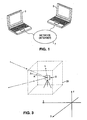
- Figure 1 shows a conventional client-server network, such as the internet.
- Figure 2 shows an illustrative graphical user interface and illustrates a feature of the present invention relating to visualizing point coordinates accurately.
- Figure 3 schematically shows a laser scanner, points collected by the laser scanner, and a mapping of the point to an image pixel space.
- FIG. 4 and Figure 5 illustrate the Figure 3 image mapping in greater detail.
- the present invention provides a point cloud viewing program for viewing point clouds in an integral, panoramic way. That is, a user can rotate the user's viewpoint up and down and right and left.
- the invention uses image maps to accomplish this visualization technique.
- a user can select one point and extract a coordinate in real space for that point or select a pair of points and measure the distance between them.
- location data of each point is available, even when viewing the panoramic image array, and the user can choose to make the location data as dimensionally accurate or nearly as dimensionally accurate as the data originally acquired by laser scanner.
- mappings such as for example, spherical mappings, in which the image coordinates map to a sphere surrounding the eye point (i.e., Mercator projections or similar), cylindrical maps, in which the image coordinates map to a cylinder surrounding the eye point, and orthographic images, in which only the view direction, scale and orientation of the image are set and all image rays are parallel.
- the invention provides for adjusting the location of each pixel representing a point in a point cloud using an offset calculated from the actual data when mapping the points onto the image map.
- the point cloud viewing program executes in an internet browser running on a client 5 in the context of a network 7.
- point cloud data is captured using conventional methods that include scanning a volume or scene using a laser scanner 9, as shown schematically in Figure 3 .
- the laser scanner 9 is well known, and the point cloud data collected by the laser scanner 9 is in a well known format and can be viewed and manipulated by a computer in well known ways.
- a data-publisher user loads the point cloud data to the network 7 and publishes it on a website.
- a website user can then view the point cloud data using a program in accordance with the invention.
- the program itself is preferably a plug-in to the internet browser, and for this purpose, is preferably embodied in a markup language, such as XML or HTML, that can be executed by an internet browser, such as MICROSOFT INTERNET EXPLORER or NETSCAPE.
- a markup language such as XML or HTML
- an internet browser such as MICROSOFT INTERNET EXPLORER or NETSCAPE.
- Figure 2 shows an illustrative user interface running in a web browser.
- the program preferably has several features for users to view and use the data displayed in the internet browser, as shown in Figure 2 . These features are subsumable into controls 20, mark-up features 22 and measurement features 24.
- the controls 20 include pan/zoom, which simply allows a user to move around the image map of the point cloud data and change the view direction.
- the controls 20 also include a hypertext mode, which is discussed in more detail below.
- the mark-up features 22 include adding text, or comment boxes, or other shapes to the image map for editing.
- editing users produce edit or mark-up objects, such as text, measurement coordinates and polygons, in a unique layer according to well known processes.
- Figure 2 shows an example of a point cloud image map with an added edit layer. The point cloud appears in a view window 26, and a user has added edits including the coordinates of a point (e.g., ⁇ 100, -75, 20 ⁇ ) and a measurement between points (e.g., 1 meter).
- the point cloud image map is shown schematically; those skilled in the art will appreciate that, in an actual embodiment, the point cloud image map will usually much more closely resemble a realistic scene.
- a user may save these edits as a file of a predetermined type.
- This file is preferably saved on a server and can be accessed and viewed by other users with access to the server.
- the file may be saved to the server, the client, or both.
- a user can simultaneously view several edit layers, from any or all of the server and client, by consecutively loading the layers.
- the edit file forming the edit layer may include vector objects that communicate distances between points or depict point coordinates in text, as shown in Figure 2 .
- the file may also include scripts or text boxes communicating miscellaneous instructions or other information.
- Figure 2 shows an illustrative user interface for performing such tasks as saving and loading mark-up layers.
- the interface includes a side panel 28, which includes such items as a view properties window and graphical instruction modules for saving and loading mark-up layers.
- the side panel 28 can also convey and allow for input of other information, such as a preferred unit of measurement, hyperlink addresses and file properties.
- the side panel 28 is only one embodiment for performing these tasks and providing this information, and one of ordinary skill in the art will appreciate that a variety of keystrokes or graphical user interfaces can be implemented to perform the same or similar tasks.
- the hypertext control freezes an image frame, assigns a name to it, and assigns a hypertext link that, when activated by a user's clicking it, brings up that frame. That is, a hyperlinking user selects a view and chooses a name for it; then the program returns a link string (e.g., something like http://www.xx.com/xxxx) that the hyperlinking user can embed in a different web page that will take a viewer wishing to see the linked page to that view.
- a link string e.g., something like http://www.xx.com/xxxx
- Hyperlinks can be any valid linkable location, such as a web location (such as http://www.yahoo.com), but could also be a local location on a computer like c: ⁇ filename.pdf or any link the browser, such as an internet browser, knows how to manage.
- An additional hyperlinking feature preferably an additional feature of the program according to the invention, relates to outgoing hyperlinks, in which a user embeds an object, such as a webpage address, into a layer comprising objects.
- a user adds a mark-up layer to a point cloud image, also called an image frame herein, as shown for example in Figure 2 .
- This mark-up layer can include coordinates and distance information, as discussed below with reference to Figure 2 , and a link to any external location on the web. In this way, a user can link to information that is relevant to a particular point cloud or any particular view of point cloud data.
- the measurement features 24 allow a user to locate points and measure distances between points. Because the point cloud data is handled by the computer as an image (i.e., in the raster domain) rather than handling each point as a vector object, there should be some way to maintain the accuracy of the locational data associated with each point despite the limitations of computer-screen resolution.
- the following discussion considered in conjunction with Figure 3 , Figure 4 and Figure 5 , describes the preferred way to maintain point accuracy.
- Figure 3 illustrates a simple example of a process for determining the offset, which gives the option to maintain the locational accuracy of individual points even when viewed as an image in an internet browser.
- the laser scanner 9 scans its surroundings, and suppose a point, point A, on the surface of an object disposed within the surroundings is scanned in 3D coordinates ⁇ x, y, z ⁇ . (As shown in Figure 3 various other points are also scanned, but for simplicity, we consider only point A.)
- An imaginary cube 30 centered at (0,0,0) is aligned to x,y,z so that the front face of the cube is in direction ⁇ 1, 0, 0 ⁇ , the top face is ⁇ 0, 0, 1 ⁇ , etc.
- the cube is defined so the faces are 2 meters by 2 meters and that the cube corners are at: ⁇ -1, -1, -1 ⁇ ; ⁇ -1, -1, 1 ⁇ ; ...; ⁇ 1, 1, 1 ⁇ .
- the cube face the ray ⁇ 0,0,0 ⁇ --> ⁇ x,y,z ⁇ passes through; 2) the location A' on the cube face that the ray ⁇ 0,0,0 ⁇ --> ⁇ x,y,z ⁇ passes through; 3) which pixel, when the point cloud data is converted into a series of images that are projected by way of a cube map, on that cube face the ray passes through; and 4) the center coordinate of that pixel and the offset from that center coordinate to the point that the ray passes through.
- the delta of, or difference between, the center coordinate of that pixel and the offset from that center coordinate to the point that the ray passes through gives the angular offset.
- pixel (0,1) we store the range: sqrt(100 ⁇ 2 + 75 ⁇ 2 + 20 ⁇ 2), and two angular offsets.
- the two angular offsets are not necessarily angles, but can be offsets on the cube face.
- the center of pixel (0,1) has coordinates ⁇ 1, -0.5, 0.5 ⁇ , so the offsets of the y,z coordinates would be (-0.25, - 0.30).
- the result can be displayed to a user that selects on a computer screen the representation of point A (as shown in Figure 2 ). The result can be used in other ways, such as to calculate the distance between two selected points.
- a computer screen comprising a plurality of pixels, as shown in Figure 4 .
- point A is represented as pixel (0,1) assuming a particular view direction and field of view.
- the pixel that represents point A can change in well-known ways as the view direction and field of view changes.
- offset coordinates can be stored at any number of levels of precision depending on what precision is needed to accurately reconstruct the point location in 3D space; the tradeoff is that higher precision requires a larger "angular offset image" and thus more bandwidth to load the web page.
- Each of the faces for the cube map is a texture map, or grid of pixel locations.
- the angle offset and range are represented in a corresponding grid of offset pairs, with one entry in the corresponding grid for each entry in the texture map image. So if there is a 50x50 texture map image for a cube face, there would be a corresponding 50x50 offset grid, where pixel (10, 5) on the texture map has its offset stored at (10,5) in the offset grid, and at (10,5) in the range grid.
- the angle offset information is stored relative to the center of the pixel. As the image is transformed to account for changes in view direction and field of view, the same transformation is applied to the angle offset and range grid.
- the image is a texture made of pixels on an even grid.
- the program determines the row and column location of that pixel and looks up the dimensional location for that row and column position stored in another file, such as an offset and/or range file.
- the offset grid and the range grid may be separate grids or combined into a single grid that corresponds to the image grid.
- the coordinates in which the location of points is expressed incorporates an arbitrary origin.
- the origin can be positioned at a given terrestrial reference point, in the manner of geographic coordinates, or at any other place.
- An illustrative non-geographic coordinate system includes a system having its origin at a point from which at least some of the points of a point cloud were taken. That is, if points were collected from only one position, the origin of the non-geographic coordinate system could be the one position of the laser scanner 9 at the time of the scan. If points were collected from two or more different positions, the origin could be one of these positions, or another position altogether.
- the choice of coordinate system is arbitrary and determined by convenience. Transforming from one coordinate system to another is simply a matter of well-known transformation techniques.
- the offset and range accuracy can be varied according to preferences relating to the size of the file on a computer disk.
- the user preferably has the authority to set the accuracy.
- the program preferably gives the browser a starting-point link to an initial file (such as an XML file) and from the starting point it finds a list of all the files it should download and intelligently retrieves them. That is, the starting file is a web page published by a publisher, and this starting file includes links that are automatically followed to other files, including image files (e.g., the texture maps) and markup files (which is a file comprising markup objects, as described previously).
- image files e.g., the texture maps
- markup files which is a file comprising markup objects, as described previously.
- the image files are preferably partitioned into levels of detail according to well-known principles.
- the files may be partitioned on the fly when needed or partitioned on the storage medium, but preferably on the storage medium.
- the browser first brings down the visible images at a level of detail that is appropriate for the user's selected view and allows the user to begin interacting with the images while the program is still working on bringing down the much larger dimensional data. This provides a near-immediate, interactive experience without any heavy weight server installation required on the web or network side.
- the stored value for each pixel in the point cloud will preferably also include red/green/blue (RGB) or greyscale color data, or some other value that can be converted to a color or greyscale value for displaying the image on the screen.
- RGB red/green/blue
- greyscale color data or some other value that can be converted to a color or greyscale value for displaying the image on the screen.
- mapping techniques of the present invention also provide for filling the gaps in the displayed image array to form a continuous image. For example, if the point spacing in a certain region of the point cloud is wider than the pixels in the image array, the "empty" pixels can filled with, for example, RGB values to make the image continuous.
- a proximity tolerance i.e., if the points are within the tolerance distance, interpolate their characteristics (e.g., color) to fill in the intermediate pixels;
- scan grid neighbors i.e., if the points are on adjacent rows or columns of the scan, interpolate to fill in the intermediate pixels;
- using colors from texture mapped images i.e., if a texture map image is applied to color the points, then apply the texture map to the pixels that contain no points by interpolating the texture coordinates of the neighboring points of the pixel and using the texture coordinates to determine the color from the texture map.
Landscapes
- Engineering & Computer Science (AREA)
- Physics & Mathematics (AREA)
- Computer Graphics (AREA)
- General Physics & Mathematics (AREA)
- Theoretical Computer Science (AREA)
- Geometry (AREA)
- Software Systems (AREA)
- Processing Or Creating Images (AREA)
- Length Measuring Devices By Optical Means (AREA)
- Image Analysis (AREA)
Claims (13)
- Verfahren zum Speichern von genauen Ortsdaten einer lasergescannten und angezeigten Szene, wobei das Verfahren umfasst:• ein Scannen einer Szene mit einem Laserscanner (9) von einer Scan-Position aus, um eine Punktwolke zu bilden, die mindestens einen Punkt (A) auf einer Oberfläche in der Szene, die von der Scan-Position aus beobachtet wird, repräsentiert;• ein Anzeigen der Punktwolke als ein Bildarray auf einem Computerbildschirm dergestalt, dass der mindestens eine Punkt (A) auf dem Computerbildschirm als ein Pixel mit einem anderen Wert als ein Hintergrundwert repräsentiert wird;
gekennzeichnet durch• ein Bestimmen eines Offset zwischen einer Bezugsposition des mindestens einen Pixels und einem Schnittpunkt (A'), wobei der Schnittpunkt (A') der Punkt ist, an dem ein Strahl von dem mindestens einen Punkt (A) zu der Scan-Position eine Ebene schneidet, die mit der Ebene des Computerbildschirms zusammenfällt, die das Pixel enthält; und• ein Speichern des Offset in einem Offset-Gitter. - Verfahren nach Anspruch 1, wobei der Schritt des Speicherns das Speichern eines Entfernungswerts des Punkts (A)• in dem Offset-Gitter, das den Bildpixeln entspricht, oder• in einem Entfernungsgitter, das von dem Offset-Gitter getrennt ist, umfasst.
- Verfahren nach Anspruch 2, ferner mit dem folgenden Schritt:• Verwenden des Pixel-Offset und des Entfernungswerts zur Berechnung einer 3D-Koordinate eines Punkts, der in dem Pixel sichtbar ist.
- Verfahren nach einem der Ansprüche 1 bis 3, wobei das Bildarray aus der folgenden Gruppe ausgewählt wird:• einem Würfelabbildungsbild,• einer sphärischen Abbildung,• einer zylindrischen Abbildung und• einer orthografischen Bildabbildung.
- Verfahren nach einem der Ansprüche 1 bis 4, wobei der Schritt des Anzeigens der Punktwolke das Bereitstellen des Bildarray für interaktive Benutzung durch einen Computerbenutzer umfasst.
- Verfahren nach Anspruch 5, wobei die interaktive Benutzung das Editieren des Bildarray durch den Computerbenutzer, um ein editiertes Bildarray bereitzustellen, umfasst.
- Verfahren nach Anspruch 6, wobei das Editieren des Bildarray das Hinzufügen von Inhalt zu dem Bildarray umfasst, wobei der hinzugefügte Inhalt insbesondere Folgendes umfasst:• ein Markup-Objekt, insbesondere Text und/oder eine Kommentarbox,• die Koordinaten des mindestens einen Punkts (A)
oder• einen Messwert zwischen dem mindestens einen Punkt (A) und einem zweiten Punkt in der Punktwolke. - Verfahren nach Anspruch 7, ferner mit dem folgenden Schritt:• Abspeichern des editierten Bildes insbesondere für Zugriff und Betrachtung durch einen anderen Computerbenutzer.
- Verfahren nach einem der Ansprüche 1 bis 8, wobei das Scannen so ausgeführt wird, dass die Punktwolke mehrere Punkte auf einer Oberfläche oder Oberflächen in der Szene repräsentiert, wodurch• jeder der mehreren Punkte auf dem Computerbildschirm als ein Pixel mit einem anderen Wert als ein Hintergrundwert repräsentiert wird und• für jeden der mehreren Punkte der Offsetwert bestimmt und in dem Offset-Gitter gespeichert wird, so dass jedes Pixel des Bildarrays einen in dem Offset-Gitter gespeicherten entsprechenden Offsetwert aufweist.
- Verfahren nach einem der Ansprüche 1 bis 9, wobei die Bezugsposition die Mitte des Pixels ist.
- Verfahren nach einem der Ansprüche 1 bis 10, wobei, falls der Punktabstand breiter als die Bildarraypixel ist, dem Bildarray zusätzliche Pixel zugeführt werden, um ein kontinuierliches Bild bereitzustellen.
- Computerprogrammprodukt, das auf einem maschinenlesbaren Medium gespeichert ist, oder Computerdatensignal, das durch eine elektromagnetische Welle realisiert wird, mit Programmanweisungen, die, wenn sie durch ein Datenverarbeitungssystem ausgeführt werden, bewirken, dass das Datenverarbeitungssystem Folgendes ausführt:• Bereitstellen von Zugriff auf eine Punktwolke, die mindestens einen Punkt (A) auf einer Oberfläche in einer Szene repräsentiert, die von einer Scan-Position aus beobachtet wird,
und mindestens die folgenden Schritte des Verfahrens nach einem der Ansprüche 1 bis 11:• Anzeigen der Punktwolke als ein Bildarray auf einem Computerbildschirm dergestalt, dass der mindestens eine Punkt (A) auf dem Computerbildschirm als ein Pixel mit einem anderen Wert als ein Hintergrundwert repräsentiert wird;• Bestimmen eines Offset zwischen einer Bezugsposition des mindestens einen Pixels und einem Schnittpunkt (A'), wobei der Schnittpunkt (A') der Punkt ist, an dem ein Strahl von dem mindestens einen Punkt (A) zu der Scan-Position eine Ebene schneidet, die mit der Ebene des Computerbildschirms zusammenfällt, die das Pixel enthält; und• Speichern des Offset in einem Offset-Gitter. - System zum Speichern von genauen Ortsdaten einer lasergescannten und angezeigten Szene, wobei das System Folgendes umfasst:• einen Laserscanner (9) zum Scannen einer Szene von einer Scan-Position aus, um eine Punktwolke zu bilden, die mindestens einen Punkt (A) auf einer Oberfläche in der Szene, die von der Scan-Position aus beobachtet wird, repräsentiert, und• einen Computerbildschirm zum Anzeigen der Punktwolke als ein Bildarray dergestalt, dass der mindestens eine Punkt (A) auf dem Computerbildschirm als ein Pixel mit einem anderen Wert als ein Hintergrundwert repräsentiert wird,
gekennzeichnet durch• eine Datenverarbeitungseinheit zum Ausführen mindestens der folgenden Schritte des Verfahrens nach einem der Ansprüche 1 bis 11:o Bestimmen eines Offset zwischen einer Bezugsposition des mindestens einen Pixels und einem Schnittpunkt (A'), wobei der Schnittpunkt (A') der Punkt ist, an dem ein Strahl von dem mindestens einen Punkt (A) zu der Scan-Position eine Ebene schneidet, die mit der Ebene des Computerbildschirms zusammenfällt, die das Pixel enthält; undo Speichern des Offset in einem Offset-Gitter.
Applications Claiming Priority (3)
| Application Number | Priority Date | Filing Date | Title |
|---|---|---|---|
| US85144406P | 2006-10-13 | 2006-10-13 | |
| US11/649,539 US7990397B2 (en) | 2006-10-13 | 2007-01-04 | Image-mapped point cloud with ability to accurately represent point coordinates |
| PCT/US2007/021298 WO2008048424A2 (en) | 2006-10-13 | 2007-10-04 | Image-mapped point cloud with ability to accurately represent point coordinates |
Publications (2)
| Publication Number | Publication Date |
|---|---|
| EP2092487A2 EP2092487A2 (de) | 2009-08-26 |
| EP2092487B1 true EP2092487B1 (de) | 2011-03-23 |
Family
ID=39144358
Family Applications (1)
| Application Number | Title | Priority Date | Filing Date |
|---|---|---|---|
| EP07839239A Active EP2092487B1 (de) | 2006-10-13 | 2007-10-04 | Bildabgebildete punktwolke mit der fähigkeit zur genauen repräsentation von punktkoordinaten |
Country Status (6)
| Country | Link |
|---|---|
| US (1) | US7990397B2 (de) |
| EP (1) | EP2092487B1 (de) |
| JP (1) | JP4819164B2 (de) |
| AT (1) | ATE503238T1 (de) |
| DE (1) | DE602007013461D1 (de) |
| WO (1) | WO2008048424A2 (de) |
Cited By (3)
| Publication number | Priority date | Publication date | Assignee | Title |
|---|---|---|---|---|
| CN104268933A (zh) * | 2014-09-11 | 2015-01-07 | 大连理工大学 | 一种车载二维激光运动中三维环境扫描成像方法 |
| CN104392480A (zh) * | 2014-11-12 | 2015-03-04 | 山东地纬数码科技有限公司 | 以内外存交换方式实现基于点的全局光照效果的渲染方法 |
| US9990340B2 (en) | 2014-02-03 | 2018-06-05 | Bluebeam, Inc. | Batch generation of links to documents based on document name and page content matching |
Families Citing this family (83)
| Publication number | Priority date | Publication date | Assignee | Title |
|---|---|---|---|---|
| JP2879202B2 (ja) | 1995-07-24 | 1999-04-05 | 東洋建設株式会社 | ロッドコンパクション工法およびその工法用補給材供給装置 |
| US7983835B2 (en) | 2004-11-03 | 2011-07-19 | Lagassey Paul J | Modular intelligent transportation system |
| KR20080064155A (ko) | 2005-10-14 | 2008-07-08 | 어플라이드 리써치 어쏘시에이츠 뉴질랜드 리미티드 | 표면 특징을 모니터링하는 방법 및 장치 |
| DE102006031580A1 (de) | 2006-07-03 | 2008-01-17 | Faro Technologies, Inc., Lake Mary | Verfahren und Vorrichtung zum dreidimensionalen Erfassen eines Raumbereichs |
| US20090231327A1 (en) * | 2008-03-12 | 2009-09-17 | Harris Corporation | Method for visualization of point cloud data |
| US20090232355A1 (en) * | 2008-03-12 | 2009-09-17 | Harris Corporation | Registration of 3d point cloud data using eigenanalysis |
| US20090232388A1 (en) * | 2008-03-12 | 2009-09-17 | Harris Corporation | Registration of 3d point cloud data by creation of filtered density images |
| US8155452B2 (en) * | 2008-10-08 | 2012-04-10 | Harris Corporation | Image registration using rotation tolerant correlation method |
| US8179393B2 (en) * | 2009-02-13 | 2012-05-15 | Harris Corporation | Fusion of a 2D electro-optical image and 3D point cloud data for scene interpretation and registration performance assessment |
| US8290305B2 (en) * | 2009-02-13 | 2012-10-16 | Harris Corporation | Registration of 3D point cloud data to 2D electro-optical image data |
| US20100208981A1 (en) * | 2009-02-13 | 2010-08-19 | Harris Corporation | Method for visualization of point cloud data based on scene content |
| DE102009015920B4 (de) | 2009-03-25 | 2014-11-20 | Faro Technologies, Inc. | Vorrichtung zum optischen Abtasten und Vermessen einer Umgebung |
| US9551575B2 (en) | 2009-03-25 | 2017-01-24 | Faro Technologies, Inc. | Laser scanner having a multi-color light source and real-time color receiver |
| DE102009035336B3 (de) | 2009-07-22 | 2010-11-18 | Faro Technologies, Inc., Lake Mary | Vorrichtung zum optischen Abtasten und Vermessen einer Umgebung |
| DE102009035337A1 (de) | 2009-07-22 | 2011-01-27 | Faro Technologies, Inc., Lake Mary | Verfahren zum optischen Abtasten und Vermessen eines Objekts |
| US20110115812A1 (en) * | 2009-11-13 | 2011-05-19 | Harris Corporation | Method for colorization of point cloud data based on radiometric imagery |
| DE102009055988B3 (de) | 2009-11-20 | 2011-03-17 | Faro Technologies, Inc., Lake Mary | Vorrichtung zum optischen Abtasten und Vermessen einer Umgebung |
| US9529083B2 (en) | 2009-11-20 | 2016-12-27 | Faro Technologies, Inc. | Three-dimensional scanner with enhanced spectroscopic energy detector |
| DE102009057101A1 (de) | 2009-11-20 | 2011-05-26 | Faro Technologies, Inc., Lake Mary | Vorrichtung zum optischen Abtasten und Vermessen einer Umgebung |
| US9113023B2 (en) | 2009-11-20 | 2015-08-18 | Faro Technologies, Inc. | Three-dimensional scanner with spectroscopic energy detector |
| US9210288B2 (en) | 2009-11-20 | 2015-12-08 | Faro Technologies, Inc. | Three-dimensional scanner with dichroic beam splitters to capture a variety of signals |
| DE102009055989B4 (de) | 2009-11-20 | 2017-02-16 | Faro Technologies, Inc. | Vorrichtung zum optischen Abtasten und Vermessen einer Umgebung |
| US9628775B2 (en) | 2010-01-20 | 2017-04-18 | Faro Technologies, Inc. | Articulated arm coordinate measurement machine having a 2D camera and method of obtaining 3D representations |
| US9879976B2 (en) | 2010-01-20 | 2018-01-30 | Faro Technologies, Inc. | Articulated arm coordinate measurement machine that uses a 2D camera to determine 3D coordinates of smoothly continuous edge features |
| US9163922B2 (en) | 2010-01-20 | 2015-10-20 | Faro Technologies, Inc. | Coordinate measurement machine with distance meter and camera to determine dimensions within camera images |
| US9607239B2 (en) | 2010-01-20 | 2017-03-28 | Faro Technologies, Inc. | Articulated arm coordinate measurement machine having a 2D camera and method of obtaining 3D representations |
| DE112011100292B4 (de) | 2010-01-20 | 2016-11-24 | Faro Technologies Inc. | Anzeige für ein Koordinatenmessgerät |
| US20110200249A1 (en) * | 2010-02-17 | 2011-08-18 | Harris Corporation | Surface detection in images based on spatial data |
| DE102010020925B4 (de) | 2010-05-10 | 2014-02-27 | Faro Technologies, Inc. | Verfahren zum optischen Abtasten und Vermessen einer Umgebung |
| US9053562B1 (en) | 2010-06-24 | 2015-06-09 | Gregory S. Rabin | Two dimensional to three dimensional moving image converter |
| DE102010032726B3 (de) | 2010-07-26 | 2011-11-24 | Faro Technologies, Inc. | Vorrichtung zum optischen Abtasten und Vermessen einer Umgebung |
| DE102010032725B4 (de) | 2010-07-26 | 2012-04-26 | Faro Technologies, Inc. | Vorrichtung zum optischen Abtasten und Vermessen einer Umgebung |
| DE102010032723B3 (de) | 2010-07-26 | 2011-11-24 | Faro Technologies, Inc. | Vorrichtung zum optischen Abtasten und Vermessen einer Umgebung |
| DE102010033561B3 (de) | 2010-07-29 | 2011-12-15 | Faro Technologies, Inc. | Vorrichtung zum optischen Abtasten und Vermessen einer Umgebung |
| US9599715B2 (en) | 2010-08-03 | 2017-03-21 | Faro Technologies, Inc. | Scanner display |
| US9168654B2 (en) | 2010-11-16 | 2015-10-27 | Faro Technologies, Inc. | Coordinate measuring machines with dual layer arm |
| US9222771B2 (en) | 2011-10-17 | 2015-12-29 | Kla-Tencor Corp. | Acquisition of information for a construction site |
| US9179844B2 (en) | 2011-11-28 | 2015-11-10 | Aranz Healthcare Limited | Handheld skin measuring or monitoring device |
| DE102012100609A1 (de) | 2012-01-25 | 2013-07-25 | Faro Technologies, Inc. | Vorrichtung zum optischen Abtasten und Vermessen einer Umgebung |
| US8396254B1 (en) * | 2012-02-09 | 2013-03-12 | Google Inc. | Methods and systems for estimating a location of a robot |
| US8705110B2 (en) * | 2012-06-25 | 2014-04-22 | Yoldas Askan | Method of generating a smooth image from point cloud data |
| US8997362B2 (en) | 2012-07-17 | 2015-04-07 | Faro Technologies, Inc. | Portable articulated arm coordinate measuring machine with optical communications bus |
| DE102012107544B3 (de) | 2012-08-17 | 2013-05-23 | Faro Technologies, Inc. | Vorrichtung zum optischen Abtasten und Vermessen einer Umgebung |
| US9513107B2 (en) | 2012-10-05 | 2016-12-06 | Faro Technologies, Inc. | Registration calculation between three-dimensional (3D) scans based on two-dimensional (2D) scan data from a 3D scanner |
| DE102012109481A1 (de) | 2012-10-05 | 2014-04-10 | Faro Technologies, Inc. | Vorrichtung zum optischen Abtasten und Vermessen einer Umgebung |
| US10067231B2 (en) | 2012-10-05 | 2018-09-04 | Faro Technologies, Inc. | Registration calculation of three-dimensional scanner data performed between scans based on measurements by two-dimensional scanner |
| US9992021B1 (en) | 2013-03-14 | 2018-06-05 | GoTenna, Inc. | System and method for private and point-to-point communication between computing devices |
| US9417911B2 (en) * | 2014-03-12 | 2016-08-16 | Live Planet Llc | Systems and methods for scalable asynchronous computing framework |
| GB2520822B (en) * | 2014-10-10 | 2016-01-13 | Aveva Solutions Ltd | Image rendering of laser scan data |
| US10869175B2 (en) | 2014-11-04 | 2020-12-15 | Nathan Schumacher | System and method for generating a three-dimensional model using flowable probes |
| US9984494B2 (en) * | 2015-01-26 | 2018-05-29 | Uber Technologies, Inc. | Map-like summary visualization of street-level distance data and panorama data |
| US20160299498A1 (en) * | 2015-04-10 | 2016-10-13 | Nanovea, Inc. | System for navigating a field of view of a displayed and magnified surface |
| CN106558017B (zh) * | 2015-09-25 | 2020-09-18 | 无锡视美乐科技股份有限公司 | 球形显示图像处理方法及系统 |
| US9652896B1 (en) | 2015-10-30 | 2017-05-16 | Snap Inc. | Image based tracking in augmented reality systems |
| US9984499B1 (en) * | 2015-11-30 | 2018-05-29 | Snap Inc. | Image and point cloud based tracking and in augmented reality systems |
| DE102015122844A1 (de) | 2015-12-27 | 2017-06-29 | Faro Technologies, Inc. | 3D-Messvorrichtung mit Batteriepack |
| US10013527B2 (en) | 2016-05-02 | 2018-07-03 | Aranz Healthcare Limited | Automatically assessing an anatomical surface feature and securely managing information related to the same |
| GB2553363B (en) * | 2016-09-05 | 2019-09-04 | Return To Scene Ltd | Method and system for recording spatial information |
| EP3315906B1 (de) * | 2016-10-27 | 2023-05-31 | Leica Geosystems AG | Verfahren zur verarbeitung von scandaten |
| EP3315907B1 (de) * | 2016-10-27 | 2025-03-26 | Leica Geosystems AG | Verfahren zur visuellen darstellung von scandaten |
| US11116407B2 (en) | 2016-11-17 | 2021-09-14 | Aranz Healthcare Limited | Anatomical surface assessment methods, devices and systems |
| US10319149B1 (en) | 2017-02-17 | 2019-06-11 | Snap Inc. | Augmented reality anamorphosis system |
| US10074381B1 (en) | 2017-02-20 | 2018-09-11 | Snap Inc. | Augmented reality speech balloon system |
| EP4183328A1 (de) | 2017-04-04 | 2023-05-24 | Aranz Healthcare Limited | Anatomische oberflächenbeurteilungsverfahren, vorrichtungen und systeme |
| US10387730B1 (en) | 2017-04-20 | 2019-08-20 | Snap Inc. | Augmented reality typography personalization system |
| US10347001B2 (en) * | 2017-04-28 | 2019-07-09 | 8th Wall Inc. | Localizing and mapping platform |
| US11378693B2 (en) | 2017-05-21 | 2022-07-05 | Timothy Coddington | Floor surveying system |
| US11422725B2 (en) * | 2017-07-25 | 2022-08-23 | General Electric Company | Point-cloud dataset storage structure and method thereof |
| US10739461B2 (en) * | 2017-12-11 | 2020-08-11 | Ford Global Technologies, Llc | Lidar point cloud compression |
| TW202006659A (zh) * | 2018-07-03 | 2020-02-01 | 財團法人工業技術研究院 | 點雲拼貼處理方法及裝置 |
| CN112789658B (zh) | 2018-10-02 | 2025-01-07 | 索尼公司 | 图像处理装置和方法 |
| US12039726B2 (en) | 2019-05-20 | 2024-07-16 | Aranz Healthcare Limited | Automated or partially automated anatomical surface assessment methods, devices and systems |
| CN111209826B (zh) * | 2019-12-31 | 2022-05-27 | 武汉中海庭数据技术有限公司 | 一种高精度地图护栏的半自动点云提取方法及装置 |
| CN111310654B (zh) * | 2020-02-13 | 2023-09-08 | 北京百度网讯科技有限公司 | 一种地图要素的定位方法、装置、电子设备及存储介质 |
| CN113435227B (zh) * | 2020-03-23 | 2023-04-07 | 阿里巴巴集团控股有限公司 | 地图生成及车辆定位方法、系统、设备及存储介质 |
| CN111462072B (zh) * | 2020-03-30 | 2023-08-29 | 北京百度网讯科技有限公司 | 点云图质量检测方法、装置以及电子设备 |
| US20220018950A1 (en) * | 2020-07-20 | 2022-01-20 | Faro Technologies, Inc. | Indoor device localization |
| WO2022141049A1 (zh) * | 2020-12-29 | 2022-07-07 | 深圳市大疆创新科技有限公司 | 激光测距装置、激光测距方法和可移动平台 |
| CN112766061B (zh) * | 2020-12-30 | 2025-05-16 | 罗普特科技集团股份有限公司 | 一种多模态无监督的行人像素级语义标注方法和系统 |
| CN113537049B (zh) * | 2021-07-14 | 2023-03-24 | 广东汇天航空航天科技有限公司 | 地面点云数据处理方法、装置、终端设备及存储介质 |
| US20250208293A1 (en) * | 2022-03-16 | 2025-06-26 | Innoviz Technologies Ltd | Determining object dimension using offset pixel grids |
| CN115035174A (zh) * | 2022-06-30 | 2022-09-09 | 梅卡曼德(北京)机器人科技有限公司 | 几何点云模型构建方法、工件抓取方法、装置和电子设备 |
| CN114937081B (zh) * | 2022-07-20 | 2022-11-18 | 之江实验室 | 基于独立非均匀增量采样的网联车位置估计方法及装置 |
Family Cites Families (5)
| Publication number | Priority date | Publication date | Assignee | Title |
|---|---|---|---|---|
| US5988862A (en) * | 1996-04-24 | 1999-11-23 | Cyra Technologies, Inc. | Integrated system for quickly and accurately imaging and modeling three dimensional objects |
| US5870220A (en) * | 1996-07-12 | 1999-02-09 | Real-Time Geometry Corporation | Portable 3-D scanning system and method for rapid shape digitizing and adaptive mesh generation |
| JP3791213B2 (ja) * | 1998-04-10 | 2006-06-28 | 日産自動車株式会社 | ぼかしオフセット曲面の作成方法 |
| US7256779B2 (en) * | 2003-05-08 | 2007-08-14 | Nintendo Co., Ltd. | Video game play using panoramically-composited depth-mapped cube mapping |
| US7477360B2 (en) * | 2005-02-11 | 2009-01-13 | Deltasphere, Inc. | Method and apparatus for displaying a 2D image data set combined with a 3D rangefinder data set |
-
2007
- 2007-01-04 US US11/649,539 patent/US7990397B2/en active Active
- 2007-10-04 EP EP07839239A patent/EP2092487B1/de active Active
- 2007-10-04 JP JP2009532361A patent/JP4819164B2/ja not_active Expired - Fee Related
- 2007-10-04 DE DE602007013461T patent/DE602007013461D1/de active Active
- 2007-10-04 AT AT07839239T patent/ATE503238T1/de not_active IP Right Cessation
- 2007-10-04 WO PCT/US2007/021298 patent/WO2008048424A2/en not_active Ceased
Cited By (7)
| Publication number | Priority date | Publication date | Assignee | Title |
|---|---|---|---|---|
| US9990340B2 (en) | 2014-02-03 | 2018-06-05 | Bluebeam, Inc. | Batch generation of links to documents based on document name and page content matching |
| US10789418B2 (en) | 2014-02-03 | 2020-09-29 | Bluebeam, Inc. | Batch generation of links to documents based on document name and page content matching |
| US11361035B2 (en) | 2014-02-03 | 2022-06-14 | Bluebeam, Inc. | Batch generation of links to documents based on document name and page content matching |
| CN104268933A (zh) * | 2014-09-11 | 2015-01-07 | 大连理工大学 | 一种车载二维激光运动中三维环境扫描成像方法 |
| CN104268933B (zh) * | 2014-09-11 | 2017-02-15 | 大连理工大学 | 一种车载二维激光运动中三维环境扫描成像方法 |
| CN104392480A (zh) * | 2014-11-12 | 2015-03-04 | 山东地纬数码科技有限公司 | 以内外存交换方式实现基于点的全局光照效果的渲染方法 |
| CN104392480B (zh) * | 2014-11-12 | 2015-09-02 | 山东地纬数码科技有限公司 | 以内外存交换方式实现基于点的全局光照效果的渲染方法 |
Also Published As
| Publication number | Publication date |
|---|---|
| JP4819164B2 (ja) | 2011-11-24 |
| DE602007013461D1 (de) | 2011-05-05 |
| WO2008048424A2 (en) | 2008-04-24 |
| EP2092487A2 (de) | 2009-08-26 |
| US20080088623A1 (en) | 2008-04-17 |
| WO2008048424A3 (en) | 2008-08-21 |
| US7990397B2 (en) | 2011-08-02 |
| JP2010507137A (ja) | 2010-03-04 |
| ATE503238T1 (de) | 2011-04-15 |
Similar Documents
| Publication | Publication Date | Title |
|---|---|---|
| EP2092487B1 (de) | Bildabgebildete punktwolke mit der fähigkeit zur genauen repräsentation von punktkoordinaten | |
| US12347016B2 (en) | Image rendering method and apparatus, device, medium, and computer program product | |
| Hanke et al. | Architectural photogrammetry: basic theory, procedures, tools | |
| CN113516769B (zh) | 虚拟现实三维场景加载与渲染方法、装置和终端设备 | |
| KR100660351B1 (ko) | 물체의 삼차원 전자 모델 발생 시스템 | |
| US8199156B2 (en) | Collaborative environments in a graphical information system | |
| KR100443552B1 (ko) | 가상 현실 구현 시스템 및 방법 | |
| US6081273A (en) | Method and system for building three-dimensional object models | |
| Cosmas et al. | 3D MURALE: A multimedia system for archaeology | |
| US20110254840A1 (en) | Automatic generation of 3d models from packaged goods product images | |
| US20140218360A1 (en) | Bim and display of 3d models on client devices | |
| EP1764744A2 (de) | Übertragung von Geometriedaten unter Verwendung einer quasipyramidalen Struktur | |
| KR20130138247A (ko) | 신속 3d 모델링 | |
| WO2009073726A1 (en) | Systems and methods for rapid three-dimensional modeling with real façade texture | |
| CA2718782A1 (en) | System and method for correlating and synchronizing a three-dimensional site model and two-dimensional imagery | |
| Bianchini et al. | The surveying and representation process applied to architecture: Non-contact methods for the documentation of cultural heritage | |
| Dorffner et al. | Generation and visualization of 3D photo-models using hybrid block adjustment with assumptions on the object shape | |
| CN111599011A (zh) | 基于WebGL技术的电力系统场景快速构建方法及系统 | |
| Lerma et al. | Three‐Dimensional city model visualisation for real‐time guided museum tours | |
| Gaiani et al. | A framework to use virtual worlds generated from real world 3D models as Work Tool for Architectural & Archaeological Restoration on the Web | |
| Grussenmeyer et al. | A comparison of photogrammetry software packages for the documentation of buildings | |
| She et al. | Rendering 2d lines on 3d terrain model with optimization in visual quality and running performance | |
| Bangay et al. | Opportunities with Slippy Maps for Terrain Visualization in Virtual and Augmented Reality | |
| Sauerbier et al. | Multi-resolution image-based visualization of archaeological landscapes in Palpa (Peru) | |
| US20240371079A1 (en) | Face-Oriented Geometry Streaming |
Legal Events
| Date | Code | Title | Description |
|---|---|---|---|
| PUAI | Public reference made under article 153(3) epc to a published international application that has entered the european phase |
Free format text: ORIGINAL CODE: 0009012 |
|
| 17P | Request for examination filed |
Effective date: 20090511 |
|
| AK | Designated contracting states |
Kind code of ref document: A2 Designated state(s): AT BE BG CH CY CZ DE DK EE ES FI FR GB GR HU IE IS IT LI LT LU LV MC MT NL PL PT RO SE SI SK TR |
|
| GRAP | Despatch of communication of intention to grant a patent |
Free format text: ORIGINAL CODE: EPIDOSNIGR1 |
|
| DAX | Request for extension of the european patent (deleted) | ||
| GRAS | Grant fee paid |
Free format text: ORIGINAL CODE: EPIDOSNIGR3 |
|
| GRAA | (expected) grant |
Free format text: ORIGINAL CODE: 0009210 |
|
| AK | Designated contracting states |
Kind code of ref document: B1 Designated state(s): AT BE BG CH CY CZ DE DK EE ES FI FR GB GR HU IE IS IT LI LT LU LV MC MT NL PL PT RO SE SI SK TR |
|
| REG | Reference to a national code |
Ref country code: GB Ref legal event code: FG4D |
|
| REG | Reference to a national code |
Ref country code: CH Ref legal event code: EP |
|
| REG | Reference to a national code |
Ref country code: IE Ref legal event code: FG4D |
|
| REG | Reference to a national code |
Ref country code: CH Ref legal event code: NV Representative=s name: KAMINSKI HARMANN PATENTANWAELTE EST. |
|
| REF | Corresponds to: |
Ref document number: 602007013461 Country of ref document: DE Date of ref document: 20110505 Kind code of ref document: P |
|
| REG | Reference to a national code |
Ref country code: DE Ref legal event code: R096 Ref document number: 602007013461 Country of ref document: DE Effective date: 20110505 |
|
| REG | Reference to a national code |
Ref country code: NL Ref legal event code: T3 |
|
| REG | Reference to a national code |
Ref country code: SE Ref legal event code: TRGR |
|
| PG25 | Lapsed in a contracting state [announced via postgrant information from national office to epo] |
Ref country code: GR Free format text: LAPSE BECAUSE OF FAILURE TO SUBMIT A TRANSLATION OF THE DESCRIPTION OR TO PAY THE FEE WITHIN THE PRESCRIBED TIME-LIMIT Effective date: 20110624 Ref country code: LV Free format text: LAPSE BECAUSE OF FAILURE TO SUBMIT A TRANSLATION OF THE DESCRIPTION OR TO PAY THE FEE WITHIN THE PRESCRIBED TIME-LIMIT Effective date: 20110323 Ref country code: LT Free format text: LAPSE BECAUSE OF FAILURE TO SUBMIT A TRANSLATION OF THE DESCRIPTION OR TO PAY THE FEE WITHIN THE PRESCRIBED TIME-LIMIT Effective date: 20110323 |
|
| LTIE | Lt: invalidation of european patent or patent extension |
Effective date: 20110323 |
|
| PG25 | Lapsed in a contracting state [announced via postgrant information from national office to epo] |
Ref country code: BG Free format text: LAPSE BECAUSE OF FAILURE TO SUBMIT A TRANSLATION OF THE DESCRIPTION OR TO PAY THE FEE WITHIN THE PRESCRIBED TIME-LIMIT Effective date: 20110623 Ref country code: CY Free format text: LAPSE BECAUSE OF FAILURE TO SUBMIT A TRANSLATION OF THE DESCRIPTION OR TO PAY THE FEE WITHIN THE PRESCRIBED TIME-LIMIT Effective date: 20110323 Ref country code: FI Free format text: LAPSE BECAUSE OF FAILURE TO SUBMIT A TRANSLATION OF THE DESCRIPTION OR TO PAY THE FEE WITHIN THE PRESCRIBED TIME-LIMIT Effective date: 20110323 Ref country code: SI Free format text: LAPSE BECAUSE OF FAILURE TO SUBMIT A TRANSLATION OF THE DESCRIPTION OR TO PAY THE FEE WITHIN THE PRESCRIBED TIME-LIMIT Effective date: 20110323 Ref country code: AT Free format text: LAPSE BECAUSE OF FAILURE TO SUBMIT A TRANSLATION OF THE DESCRIPTION OR TO PAY THE FEE WITHIN THE PRESCRIBED TIME-LIMIT Effective date: 20110323 |
|
| PG25 | Lapsed in a contracting state [announced via postgrant information from national office to epo] |
Ref country code: BE Free format text: LAPSE BECAUSE OF FAILURE TO SUBMIT A TRANSLATION OF THE DESCRIPTION OR TO PAY THE FEE WITHIN THE PRESCRIBED TIME-LIMIT Effective date: 20110323 |
|
| PG25 | Lapsed in a contracting state [announced via postgrant information from national office to epo] |
Ref country code: EE Free format text: LAPSE BECAUSE OF FAILURE TO SUBMIT A TRANSLATION OF THE DESCRIPTION OR TO PAY THE FEE WITHIN THE PRESCRIBED TIME-LIMIT Effective date: 20110323 Ref country code: PT Free format text: LAPSE BECAUSE OF FAILURE TO SUBMIT A TRANSLATION OF THE DESCRIPTION OR TO PAY THE FEE WITHIN THE PRESCRIBED TIME-LIMIT Effective date: 20110725 |
|
| PG25 | Lapsed in a contracting state [announced via postgrant information from national office to epo] |
Ref country code: RO Free format text: LAPSE BECAUSE OF FAILURE TO SUBMIT A TRANSLATION OF THE DESCRIPTION OR TO PAY THE FEE WITHIN THE PRESCRIBED TIME-LIMIT Effective date: 20110323 Ref country code: SK Free format text: LAPSE BECAUSE OF FAILURE TO SUBMIT A TRANSLATION OF THE DESCRIPTION OR TO PAY THE FEE WITHIN THE PRESCRIBED TIME-LIMIT Effective date: 20110323 Ref country code: IS Free format text: LAPSE BECAUSE OF FAILURE TO SUBMIT A TRANSLATION OF THE DESCRIPTION OR TO PAY THE FEE WITHIN THE PRESCRIBED TIME-LIMIT Effective date: 20110723 Ref country code: ES Free format text: LAPSE BECAUSE OF FAILURE TO SUBMIT A TRANSLATION OF THE DESCRIPTION OR TO PAY THE FEE WITHIN THE PRESCRIBED TIME-LIMIT Effective date: 20110704 Ref country code: CZ Free format text: LAPSE BECAUSE OF FAILURE TO SUBMIT A TRANSLATION OF THE DESCRIPTION OR TO PAY THE FEE WITHIN THE PRESCRIBED TIME-LIMIT Effective date: 20110323 |
|
| PLBE | No opposition filed within time limit |
Free format text: ORIGINAL CODE: 0009261 |
|
| STAA | Information on the status of an ep patent application or granted ep patent |
Free format text: STATUS: NO OPPOSITION FILED WITHIN TIME LIMIT |
|
| 26N | No opposition filed |
Effective date: 20111227 |
|
| PG25 | Lapsed in a contracting state [announced via postgrant information from national office to epo] |
Ref country code: PL Free format text: LAPSE BECAUSE OF FAILURE TO SUBMIT A TRANSLATION OF THE DESCRIPTION OR TO PAY THE FEE WITHIN THE PRESCRIBED TIME-LIMIT Effective date: 20110323 Ref country code: DK Free format text: LAPSE BECAUSE OF FAILURE TO SUBMIT A TRANSLATION OF THE DESCRIPTION OR TO PAY THE FEE WITHIN THE PRESCRIBED TIME-LIMIT Effective date: 20110323 |
|
| REG | Reference to a national code |
Ref country code: DE Ref legal event code: R097 Ref document number: 602007013461 Country of ref document: DE Effective date: 20111227 |
|
| PG25 | Lapsed in a contracting state [announced via postgrant information from national office to epo] |
Ref country code: MC Free format text: LAPSE BECAUSE OF NON-PAYMENT OF DUE FEES Effective date: 20111031 Ref country code: IT Free format text: LAPSE BECAUSE OF FAILURE TO SUBMIT A TRANSLATION OF THE DESCRIPTION OR TO PAY THE FEE WITHIN THE PRESCRIBED TIME-LIMIT Effective date: 20110323 |
|
| REG | Reference to a national code |
Ref country code: IE Ref legal event code: MM4A |
|
| PG25 | Lapsed in a contracting state [announced via postgrant information from national office to epo] |
Ref country code: IE Free format text: LAPSE BECAUSE OF NON-PAYMENT OF DUE FEES Effective date: 20111004 |
|
| PG25 | Lapsed in a contracting state [announced via postgrant information from national office to epo] |
Ref country code: MT Free format text: LAPSE BECAUSE OF FAILURE TO SUBMIT A TRANSLATION OF THE DESCRIPTION OR TO PAY THE FEE WITHIN THE PRESCRIBED TIME-LIMIT Effective date: 20110323 |
|
| PG25 | Lapsed in a contracting state [announced via postgrant information from national office to epo] |
Ref country code: LU Free format text: LAPSE BECAUSE OF NON-PAYMENT OF DUE FEES Effective date: 20111004 |
|
| PG25 | Lapsed in a contracting state [announced via postgrant information from national office to epo] |
Ref country code: TR Free format text: LAPSE BECAUSE OF FAILURE TO SUBMIT A TRANSLATION OF THE DESCRIPTION OR TO PAY THE FEE WITHIN THE PRESCRIBED TIME-LIMIT Effective date: 20110323 |
|
| PG25 | Lapsed in a contracting state [announced via postgrant information from national office to epo] |
Ref country code: HU Free format text: LAPSE BECAUSE OF FAILURE TO SUBMIT A TRANSLATION OF THE DESCRIPTION OR TO PAY THE FEE WITHIN THE PRESCRIBED TIME-LIMIT Effective date: 20110323 |
|
| REG | Reference to a national code |
Ref country code: FR Ref legal event code: PLFP Year of fee payment: 10 |
|
| REG | Reference to a national code |
Ref country code: FR Ref legal event code: PLFP Year of fee payment: 11 |
|
| REG | Reference to a national code |
Ref country code: FR Ref legal event code: PLFP Year of fee payment: 12 |
|
| PGFP | Annual fee paid to national office [announced via postgrant information from national office to epo] |
Ref country code: SE Payment date: 20190923 Year of fee payment: 13 Ref country code: NL Payment date: 20190925 Year of fee payment: 13 |
|
| REG | Reference to a national code |
Ref country code: SE Ref legal event code: EUG |
|
| REG | Reference to a national code |
Ref country code: NL Ref legal event code: MM Effective date: 20201101 |
|
| PG25 | Lapsed in a contracting state [announced via postgrant information from national office to epo] |
Ref country code: NL Free format text: LAPSE BECAUSE OF NON-PAYMENT OF DUE FEES Effective date: 20201101 |
|
| PG25 | Lapsed in a contracting state [announced via postgrant information from national office to epo] |
Ref country code: SE Free format text: LAPSE BECAUSE OF NON-PAYMENT OF DUE FEES Effective date: 20201005 |
|
| PGFP | Annual fee paid to national office [announced via postgrant information from national office to epo] |
Ref country code: GB Payment date: 20240919 Year of fee payment: 18 |
|
| PGFP | Annual fee paid to national office [announced via postgrant information from national office to epo] |
Ref country code: FR Payment date: 20240919 Year of fee payment: 18 |
|
| PGFP | Annual fee paid to national office [announced via postgrant information from national office to epo] |
Ref country code: DE Payment date: 20240919 Year of fee payment: 18 |
|
| PGFP | Annual fee paid to national office [announced via postgrant information from national office to epo] |
Ref country code: CH Payment date: 20241101 Year of fee payment: 18 |