EP2092614B1 - Fiche coaxiale à relier à un connecteur coaxial bnc - Google Patents
Fiche coaxiale à relier à un connecteur coaxial bnc Download PDFInfo
- Publication number
- EP2092614B1 EP2092614B1 EP07856428A EP07856428A EP2092614B1 EP 2092614 B1 EP2092614 B1 EP 2092614B1 EP 07856428 A EP07856428 A EP 07856428A EP 07856428 A EP07856428 A EP 07856428A EP 2092614 B1 EP2092614 B1 EP 2092614B1
- Authority
- EP
- European Patent Office
- Prior art keywords
- coaxial
- bnc
- plug
- latching
- coaxial plug
- Prior art date
- Legal status (The legal status is an assumption and is not a legal conclusion. Google has not performed a legal analysis and makes no representation as to the accuracy of the status listed.)
- Active
Links
Images

Classifications
-
- H—ELECTRICITY
- H01—ELECTRIC ELEMENTS
- H01R—ELECTRICALLY-CONDUCTIVE CONNECTIONS; STRUCTURAL ASSOCIATIONS OF A PLURALITY OF MUTUALLY-INSULATED ELECTRICAL CONNECTING ELEMENTS; COUPLING DEVICES; CURRENT COLLECTORS
- H01R13/00—Details of coupling devices of the kinds covered by groups H01R12/70 or H01R24/00 - H01R33/00
- H01R13/62—Means for facilitating engagement or disengagement of coupling parts or for holding them in engagement
- H01R13/629—Additional means for facilitating engagement or disengagement of coupling parts, e.g. aligning or guiding means, levers, gas pressure electrical locking indicators, manufacturing tolerances
- H01R13/633—Additional means for facilitating engagement or disengagement of coupling parts, e.g. aligning or guiding means, levers, gas pressure electrical locking indicators, manufacturing tolerances for disengagement only
- H01R13/6335—Additional means for facilitating engagement or disengagement of coupling parts, e.g. aligning or guiding means, levers, gas pressure electrical locking indicators, manufacturing tolerances for disengagement only comprising a handle
-
- H—ELECTRICITY
- H01—ELECTRIC ELEMENTS
- H01R—ELECTRICALLY-CONDUCTIVE CONNECTIONS; STRUCTURAL ASSOCIATIONS OF A PLURALITY OF MUTUALLY-INSULATED ELECTRICAL CONNECTING ELEMENTS; COUPLING DEVICES; CURRENT COLLECTORS
- H01R13/00—Details of coupling devices of the kinds covered by groups H01R12/70 or H01R24/00 - H01R33/00
- H01R13/62—Means for facilitating engagement or disengagement of coupling parts or for holding them in engagement
- H01R13/625—Casing or ring with bayonet engagement
-
- H—ELECTRICITY
- H01—ELECTRIC ELEMENTS
- H01R—ELECTRICALLY-CONDUCTIVE CONNECTIONS; STRUCTURAL ASSOCIATIONS OF A PLURALITY OF MUTUALLY-INSULATED ELECTRICAL CONNECTING ELEMENTS; COUPLING DEVICES; CURRENT COLLECTORS
- H01R24/00—Two-part coupling devices, or either of their cooperating parts, characterised by their overall structure
- H01R24/38—Two-part coupling devices, or either of their cooperating parts, characterised by their overall structure having concentrically or coaxially arranged contacts
- H01R24/40—Two-part coupling devices, or either of their cooperating parts, characterised by their overall structure having concentrically or coaxially arranged contacts specially adapted for high frequency
-
- H—ELECTRICITY
- H01—ELECTRIC ELEMENTS
- H01R—ELECTRICALLY-CONDUCTIVE CONNECTIONS; STRUCTURAL ASSOCIATIONS OF A PLURALITY OF MUTUALLY-INSULATED ELECTRICAL CONNECTING ELEMENTS; COUPLING DEVICES; CURRENT COLLECTORS
- H01R2103/00—Two poles
Definitions
- the present invention relates to a coaxial connector having a housing, a plug-side end for connection to a BNC coaxial socket, which has two BNC pins of a bayonet fitting, and a cable-side end for connection to an RF transmission line, in particular a coaxial cable, according to the preamble of Claim 1, as in US-A-2005/0037652 disclosed.
- BNC coaxial sockets B Ajonett N avi C onnector
- additional electrical connection lines between the probe and the meter are required to transmit, for example, more signals or a supply voltage for the probe. Since it is a peculiarity of the bayonet-type BNC connector that the BNC coaxial connector is freely rotatable relative to the BNC coaxial socket, these additional connection lines can not initially be made through the BNC connector.
- the invention is based on the object, a coaxial connector of o.g. To design the type such that regardless of the shape of the housing of the coaxial plug a twist-proof connector with a BNC coaxial socket and with a predetermined orientation relative to this BNC coaxial socket can be produced.
- the housing of the coaxial connector has two oppositely disposed, starting from the plug-side end of the coaxial connector extending in the axial direction slots, which are each arranged and adapted for receiving a BNC pin such that these each form an axial stop for a BNC pin, wherein on the housing of the coaxial connector a locking fork is arranged, which has two locking prongs, each detent tangentially overlaps an axial slot of the housing of the coaxial connector between the stop and the plug-side end of the coaxial plug, that when plugged into the BNC coaxial jack coaxial each BNC pin between a locking prongs and a stop of the axial slot is held and establishes a locked connection between the coaxial connector and the BNC coaxial socket, wherein the locking fork pivotally to de m housing of the coaxial connector and disposed between a locking position in which the locking prongs the axial slots tangentially overlap, and a release position in
- Rotary sleeve for a bayonet lock not according to the BNC standard corresponding coaxial plug is reliably connected to a BNC socket, at the same time through the axial slots a predetermined orientation between coaxial and BNC coaxial jack and a fuse against a twisting of the coaxial connector relative to the BNC coaxial jack ge personallyrleitstet is.
- the axial slots cooperate with the BNC pins to form a guide for the coaxial connector when pushed axially onto the BNC socket and limit the axial insertion depth with the stop.
- the locking fork is present for locking, so that instead of a rotary movement for locking a bayonet lock only the locking fork must be pivoted to the locking position to produce a firmly locked connection between the coaxial connector and the BNC socket.
- An automatic locking of the coaxial connector to the BNC coaxial socket by means of the locking fork is achieved in that the locking fork is acted upon in the direction of the locking position with an elastic spring force.
- the latching connecting the coaxial connector with the BNC coaxial socket by simply manually sliding the coaxial connector on the BNC coaxial socket, which engages without additional manual activities, the locking of the locking fork to the BNC pins.
- the axial slots are formed such that the BNC pins project radially outward of the housing.
- each latching prongs zugewanden on a side facing the plug-side end of the coaxial plug side has a first inclined surface such that seen in the locking position of the locking fork in the direction of the plug-side end of the coaxial connector to the cable end of the coaxial connector increases the tangential coverage of the axial slot through the locking prongs, when plugging the coaxial connector on the BNC socket, the locking fork of the BNC pins automatically in the Release position pivoted.
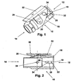
- the cable end serves to connect the coaxial connector 10 to an RF transmission line, such as a coaxial cable.
- a locking fork 22 is pivotally mounted about a pivot axis 24.
- the latching fork 22 comprises two latching prongs 26, one of which covers an axial slot 18 tangentially between the plug-side end 12 and the stopper 20 when the latching fork 22 in the in Fig. 1 and 2 is shown locking position.
- a leaf spring 28 acts on the latching fork 22 with an elastic spring force such that the latching fork 22 is pressed into the locking position.
- the locking fork 22 Upon pressure on the locking fork 22 at the point indicated by arrow 30, the locking fork 22 is pivoted about the pivot axis 24 in a release position (not shown) in which the locking prongs 26, the axial slots 18 no longer cover, so that the axial slots 18th are freely continuous in the axial direction.
- Each locking prongs 26 has at a plug-side end 12 of the coaxial connector 10 side facing a first inclined surface 32 such that seen in the locking position of the locking fork 22 in the direction of the plug-side end 12 of the coaxial connector 10 to the cable end 14 of the coaxial connector 10, the tangential Covering of the axial slot 18 by the locking prongs 26 increases, in particular from Fig. 2 seen.
- Each locking prongs 26 has on a side facing the cable end 14 of the coaxial connector 10 a second inclined surface 34 such that seen in the locking position of the locking fork 22 in the direction of the plug-side end 12 of the coaxial connector 10 to the cable-side end 14 of the coaxial connector 10, the tangential Covering of the axial slot 18 by the locking prongs 26 decreases, as in particular Fig. 2 seen.
- the 3 and 4 illustrate the coaxial connector 10 according to the invention in a plugged onto a BNC coaxial socket 36 state.
- This BNC coaxial socket 36 includes two BNC pins 38, which are originally for a known bayonet lock a suitably designed BNC connector with bayonet rotary sleeve, as is common with BNC connectors.
- the axial slots 18 engage over the BNC pins 38, so that the coaxial connector 10 according to the invention only in a certain position relative to the BNC coaxial socket 36 this can be plugged.
- the BNC pins 38 cooperating with the coaxial slots 18 additionally form a guide and an anti-twist device.
- the BNC pins 38 which project beyond the housing 16 in the radial direction, first slide along the first inclined surfaces 32 of the latching prongs 26 and thereby push or pivot the latching fork 22 counter to elastic spring force of the leaf spring 28 from the locking position to the release position. Thereby, the axial slots 18 are released and the BNC pins 38 can be further inserted in and along the axial slots 18 up to the respective stops 20 in the axial direction.
- the BNC pins 38 leave the region of the first inclined surfaces 32 and the locking fork 22 pivots under the elastic spring force of the leaf spring 28 back into the locking position.
- the BNC pins 38 are locked between the stops 20 and the locking prongs 26 and can not be pulled out of the axial slots 18 in the direction of arrow 40 again.
- the coaxial connector 10 and the BNC coaxial connector 36 are fixedly connected to each other.
- the second inclined surfaces 34 of the locking prongs 26 press on the BNC pins 38 under the action of the elastic spring force of the leaf spring 28, so that they are pressed in the direction or against the stops 20 or against the direction of arrow 40. This produces a corresponding contact pressure for establishing electrical contact between the coaxial connector 10 and the BNC coaxial connector 36.
- the mechanical and electrical connection of the coaxial connector 10 to the BNC coaxial connector 36 is made by simply attaching the coaxial connector 10 to the BNC coaxial connector 36 in the insertion direction 40 to the BNC pins 38 strike the attacks 20.
- the locking connection between coaxial connector 10 and BNC coaxial socket 36 is thereby automatically produced by the locking fork 22.
- a pressure is manually exerted on the locking fork 22 at arrow 30, so that the locking fork 22 is pivoted against the elastic spring force of the leaf spring 28 in the release position about the pivot axis 24.
Landscapes
- Details Of Connecting Devices For Male And Female Coupling (AREA)
- Coupling Device And Connection With Printed Circuit (AREA)
Claims (5)
- Connecteur coaxial mâle (10) comprenant un boîtier (16), une extrémité côté enfichage (12) à relier avec un connecteur coaxial femelle BNC (36) qui comporte deux ergots BNC (38) d'une fermeture à baïonnette, et une extrémité côté câble (14) pour la liaison avec une ligne de transmission HF, en particulier un câble coaxial,
caractérisé en ce que
le boîtier (16) du connecteur coaxial mâle (10) comporte deux fentes (18) agencées en opposition et s'étendant en direction axiale en partant de l'extrémité côté enfichage (12) du connecteur coaxial mâle (10), lesdites fentes étant agencées et réalisées pour la réception d'un ergot BNC (38) de telle manière qu'elles forment respectivement une butée axiale (20) pour un ergot BNC (38), dans lequel une fourchette d'enclenchement (22) est agencée sur le boîtier (16) du connecteur coaxial mâle (10), laquelle comporte deux doigts d'enclenchement (26), tels que chaque doigt d'enclenchement ou (26) coiffe tangentiellement une fente axiale (18) du boîtier (16) du connecteur coaxial mâle (10) entre la butée (20) et l'extrémité côté enfichage (12) du connecteur coaxial mâle (10) de telle façon que lorsque le connecteur coaxial mâle (10) est enfiché dans le connecteur coaxial femelle BNC (36) un ergot BNC (38) est respectivement fermement maintenu entre un doigt d'enclenchement (26) et une butée (20) de la fente axiale (18) et établit une liaison verrouillée entre le connecteur coaxial mâle (10) et le connecteur coaxial femelle BNC (36), et la fourchette d'enclenchement (22) est agencée en pivotement sur le boîtier (16) du connecteur coaxial mâle (10) est capable de pivoter entre une position de verrouillage, dans laquelle les doigts d'enclenchement (26) recouvrent tangentiellement les fentes axiales (18), et une position de libération, dans laquelle les doigts d'enclenchement (26) dégagent les fentes axiales (18) sur la totalité de leur longueur de sorte que les ergots BNC (38) peuvent être enfichés en direction axiale dans les fentes axiales (18) ou être extraits hors de celles-ci en direction axiale. - Connecteur coaxial mâle (10) selon la revendication 1, caractérisé en ce que la fourchette d'enclenchement (22) est sollicitée avec une force élastique en direction de la position de verrouillage.
- Connecteur coaxial mâle (10) selon la revendication 1 ou 2, caractérisé en ce que les fentes axiales (18) sont réalisées de telle manière que les ergots BNC (38) dépassent radialement vers l'extérieur depuis le boîtier (16).
- Connecteur coaxial mâle (10) selon l'une au moins des revendications précédentes, caractérisé en ce que chaque doigt d'enclenchement (26) comporte, sur un côté tourné vers l'extrémité côté enfichage (12) du connecteur coaxial mâle (10), une première surface en biais (32) de telle façon que, dans la position de verrouillage de la fourchette d'enclenchement (22), le recouvrement tangentiel de la fente axiale (18) par les doigts d'enclenchement (26) augmente, considéré en direction depuis l'extrémité côté enfichage (12) du connecteur coaxial mâle (10) jusqu'à l'extrémité côté câble (14) du connecteur coaxial mâle (10).
- Connecteur coaxial mâle (10) selon l'une au moins des revendications précédentes, caractérisé en ce que chaque doigt d'enclenchement (26) comporte, sur un côté tourné vers l'extrémité côté câble (14) du connecteur coaxial mâle (10), une seconde surface en biais (34) de telle façon que, dans la position de verrouillage de la fourchette d'enclenchement (22), le recouvrement tangentiel de la fente axiale (18) par les doigts d'enclenchement (26) diminue, considéré en direction depuis l'extrémité côté enfichage (12) du connecteur coaxial mâle (10) jusqu'à l'extrémité côté câble (14) du connecteur coaxial mâle (10).
Applications Claiming Priority (2)
| Application Number | Priority Date | Filing Date | Title |
|---|---|---|---|
| DE202006019203U DE202006019203U1 (de) | 2006-12-20 | 2006-12-20 | Koaxialstecker zum Verbinden mit einer BNC-Koaxialbuchse |
| PCT/EP2007/010623 WO2008080501A1 (fr) | 2006-12-20 | 2007-12-06 | Fiche coaxiale à relier à un connecteur coaxial bnc |
Publications (2)
| Publication Number | Publication Date |
|---|---|
| EP2092614A1 EP2092614A1 (fr) | 2009-08-26 |
| EP2092614B1 true EP2092614B1 (fr) | 2010-04-28 |
Family
ID=37833217
Family Applications (1)
| Application Number | Title | Priority Date | Filing Date |
|---|---|---|---|
| EP07856428A Active EP2092614B1 (fr) | 2006-12-20 | 2007-12-06 | Fiche coaxiale à relier à un connecteur coaxial bnc |
Country Status (6)
| Country | Link |
|---|---|
| US (1) | US7905742B2 (fr) |
| EP (1) | EP2092614B1 (fr) |
| CN (1) | CN101595605B (fr) |
| AT (1) | ATE466390T1 (fr) |
| DE (2) | DE202006019203U1 (fr) |
| WO (1) | WO2008080501A1 (fr) |
Families Citing this family (6)
| Publication number | Priority date | Publication date | Assignee | Title |
|---|---|---|---|---|
| JP5466025B2 (ja) * | 2010-01-22 | 2014-04-09 | 矢崎総業株式会社 | 嵌合補助治具及びこれを用いたコネクタ |
| US9052473B2 (en) * | 2012-11-02 | 2015-06-09 | Samtec, Inc. | Pivoting latch for cable housing |
| EP3028080A1 (fr) * | 2013-07-31 | 2016-06-08 | Corning Optical Communication Llc | Sous-ensembles de connecteur de fibres optiques ayant un organe de maintien de ferrule à verrouillage à chargement par l'avant et composants de fibre optique, dispositifs et procédés associés |
| US9577377B1 (en) * | 2016-01-11 | 2017-02-21 | Sumitomo Wiring Systems, Ltd. | Connector assembly with lever and shroud |
| DE102019125827A1 (de) * | 2019-09-25 | 2021-03-25 | Endress+Hauser Flowtec Ag | Elektrischer Verbinder und Feldgerät der Mess-/Automatisierungstechnik |
| GB2603965A (en) * | 2021-02-23 | 2022-08-24 | Cambridge Electronic Ind Ltd | Locking connector |
Family Cites Families (8)
| Publication number | Priority date | Publication date | Assignee | Title |
|---|---|---|---|---|
| JP2500247Y2 (ja) * | 1991-06-03 | 1996-06-05 | 矢崎総業株式会社 | レバ―付コネクタ |
| JP2762896B2 (ja) * | 1993-06-14 | 1998-06-04 | 住友電装株式会社 | レバー式コネクタ |
| JP3000129B2 (ja) * | 1994-09-06 | 2000-01-17 | 矢崎総業株式会社 | レバー式コネクタ |
| US5823808A (en) * | 1996-08-20 | 1998-10-20 | Chrysler Corporation | Cam lever operated connector |
| DE19923386C1 (de) * | 1999-05-21 | 2001-01-18 | Framatome Connectors Int | Elektrischer Steckverbinder, insbesondere für Kraftfahrzeuganwendungen |
| JP3538750B2 (ja) * | 1999-08-02 | 2004-06-14 | 住友電装株式会社 | レバー式コネクタ |
| JP2001237026A (ja) * | 2000-02-23 | 2001-08-31 | Yazaki Corp | レバー付コネクタ |
| US6921283B2 (en) * | 2001-08-27 | 2005-07-26 | Trompeter Electronics, Inc. | BNC connector having visual indication |
-
2006
- 2006-12-20 DE DE202006019203U patent/DE202006019203U1/de not_active Expired - Lifetime
-
2007
- 2007-12-06 EP EP07856428A patent/EP2092614B1/fr active Active
- 2007-12-06 CN CN2007800470293A patent/CN101595605B/zh active Active
- 2007-12-06 US US12/520,367 patent/US7905742B2/en active Active
- 2007-12-06 AT AT07856428T patent/ATE466390T1/de active
- 2007-12-06 DE DE502007003629T patent/DE502007003629D1/de active Active
- 2007-12-06 WO PCT/EP2007/010623 patent/WO2008080501A1/fr not_active Ceased
Also Published As
| Publication number | Publication date |
|---|---|
| US7905742B2 (en) | 2011-03-15 |
| EP2092614A1 (fr) | 2009-08-26 |
| HK1139511A1 (en) | 2010-09-17 |
| CN101595605B (zh) | 2011-09-07 |
| US20100105234A1 (en) | 2010-04-29 |
| ATE466390T1 (de) | 2010-05-15 |
| DE502007003629D1 (de) | 2010-06-10 |
| CN101595605A (zh) | 2009-12-02 |
| WO2008080501A1 (fr) | 2008-07-10 |
| DE202006019203U1 (de) | 2007-02-22 |
Similar Documents
| Publication | Publication Date | Title |
|---|---|---|
| EP1222717B1 (fr) | Connecteur enfichable coaxial | |
| EP1977484A1 (fr) | Arrangement de connecteur coaxial | |
| EP1955413B1 (fr) | Connecteur coaxial push-pull | |
| EP1239550B1 (fr) | Connecteur à fiche | |
| EP1747604B1 (fr) | Systeme d'accouplement de boitier pour connecteur a fiche coaxial | |
| EP0772261A2 (fr) | Connecteur coaxial | |
| EP4066325B1 (fr) | Appareil de verrouillage secondaire | |
| EP4000139B1 (fr) | Élément de contact | |
| DE1956162B2 (de) | Elektrische Steckverbindung | |
| WO2016173698A1 (fr) | Connexion par enfichage et jeu de connexions par enfichage | |
| EP3109949A1 (fr) | Connecteur a fiches et connecteur femelle | |
| EP2092614A1 (fr) | Fiche coaxiale à relier à un connecteur coaxial bnc | |
| DE202015001331U1 (de) | Steckverbinder mit Dämpfungselement | |
| DE102016108621B4 (de) | Steckverbindergehäuse und Steckverbinder | |
| WO2021078601A1 (fr) | Dispositif terminal servant à connecter un conducteur électrique | |
| DE102006025346B4 (de) | Steckverbindung mit einem Hebel | |
| EP1744408B1 (fr) | Connexion enfichable électrique | |
| DE202006020191U1 (de) | Steckvorrichtung nach EN 60 309 mit einem Drehkörper zur Abdichtung und Verriegelung ohne Klappdeckel | |
| EP4312322B1 (fr) | Connecteur réseau et connexion enfichable | |
| DE20318593U1 (de) | Anordnung eines Elementes in einem Rundsteckverbinder | |
| DE102012111125B4 (de) | RJ45-Stecker und Steckverbinderanordnung mit Positionierungselement | |
| WO2020064804A1 (fr) | Connecteur à enfichage électrique | |
| DE102010028802B4 (de) | Stecker mit einem Sperrelement | |
| DE102013014202B4 (de) | Steckverbindersystem | |
| AT410616B (de) | Elektrischer kabelstecker |
Legal Events
| Date | Code | Title | Description |
|---|---|---|---|
| PUAI | Public reference made under article 153(3) epc to a published international application that has entered the european phase |
Free format text: ORIGINAL CODE: 0009012 |
|
| 17P | Request for examination filed |
Effective date: 20090526 |
|
| AK | Designated contracting states |
Kind code of ref document: A1 Designated state(s): AT BE BG CH CY CZ DE DK EE ES FI FR GB GR HU IE IS IT LI LT LU LV MC MT NL PL PT RO SE SI SK TR |
|
| RIN1 | Information on inventor provided before grant (corrected) |
Inventor name: WOLLITZER, MICHAEL Inventor name: REICHEL, THOMAS Inventor name: KOENIG, HANS-DIETER Inventor name: HAGENBUSCH, RALF Inventor name: TATZEL, FRANK Inventor name: PESCHKE, MARTIN Inventor name: ULLRICH, STEFAN Inventor name: BABINGER, HERBERT Inventor name: FUEHRICH, MANUELA |
|
| RIN1 | Information on inventor provided before grant (corrected) |
Inventor name: FUEHRICH, MANUELA Inventor name: WOLLITZER, MICHAEL Inventor name: ULLRICH, STEFAN Inventor name: HAGENBUSCH, RALF Inventor name: BABINGER, HERBERT Inventor name: KOENIG, HANS-DIETER Inventor name: TATZEL, FRANK Inventor name: PESCHKE, MARTIN Inventor name: REICHEL, THOMAS |
|
| GRAP | Despatch of communication of intention to grant a patent |
Free format text: ORIGINAL CODE: EPIDOSNIGR1 |
|
| DAX | Request for extension of the european patent (deleted) | ||
| GRAS | Grant fee paid |
Free format text: ORIGINAL CODE: EPIDOSNIGR3 |
|
| GRAA | (expected) grant |
Free format text: ORIGINAL CODE: 0009210 |
|
| AK | Designated contracting states |
Kind code of ref document: B1 Designated state(s): AT BE BG CH CY CZ DE DK EE ES FI FR GB GR HU IE IS IT LI LT LU LV MC MT NL PL PT RO SE SI SK TR |
|
| REG | Reference to a national code |
Ref country code: GB Ref legal event code: FG4D Free format text: NOT ENGLISH |
|
| REG | Reference to a national code |
Ref country code: CH Ref legal event code: EP |
|
| REG | Reference to a national code |
Ref country code: IE Ref legal event code: FG4D Free format text: LANGUAGE OF EP DOCUMENT: GERMAN |
|
| REF | Corresponds to: |
Ref document number: 502007003629 Country of ref document: DE Date of ref document: 20100610 Kind code of ref document: P |
|
| REG | Reference to a national code |
Ref country code: NL Ref legal event code: VDEP Effective date: 20100428 |
|
| LTIE | Lt: invalidation of european patent or patent extension |
Effective date: 20100428 |
|
| PG25 | Lapsed in a contracting state [announced via postgrant information from national office to epo] |
Ref country code: SE Free format text: LAPSE BECAUSE OF FAILURE TO SUBMIT A TRANSLATION OF THE DESCRIPTION OR TO PAY THE FEE WITHIN THE PRESCRIBED TIME-LIMIT Effective date: 20100428 Ref country code: ES Free format text: LAPSE BECAUSE OF FAILURE TO SUBMIT A TRANSLATION OF THE DESCRIPTION OR TO PAY THE FEE WITHIN THE PRESCRIBED TIME-LIMIT Effective date: 20100808 Ref country code: LT Free format text: LAPSE BECAUSE OF FAILURE TO SUBMIT A TRANSLATION OF THE DESCRIPTION OR TO PAY THE FEE WITHIN THE PRESCRIBED TIME-LIMIT Effective date: 20100428 Ref country code: NL Free format text: LAPSE BECAUSE OF FAILURE TO SUBMIT A TRANSLATION OF THE DESCRIPTION OR TO PAY THE FEE WITHIN THE PRESCRIBED TIME-LIMIT Effective date: 20100428 |
|
| REG | Reference to a national code |
Ref country code: IE Ref legal event code: FD4D |
|
| PG25 | Lapsed in a contracting state [announced via postgrant information from national office to epo] |
Ref country code: LV Free format text: LAPSE BECAUSE OF FAILURE TO SUBMIT A TRANSLATION OF THE DESCRIPTION OR TO PAY THE FEE WITHIN THE PRESCRIBED TIME-LIMIT Effective date: 20100428 Ref country code: SI Free format text: LAPSE BECAUSE OF FAILURE TO SUBMIT A TRANSLATION OF THE DESCRIPTION OR TO PAY THE FEE WITHIN THE PRESCRIBED TIME-LIMIT Effective date: 20100428 Ref country code: FI Free format text: LAPSE BECAUSE OF FAILURE TO SUBMIT A TRANSLATION OF THE DESCRIPTION OR TO PAY THE FEE WITHIN THE PRESCRIBED TIME-LIMIT Effective date: 20100428 Ref country code: IS Free format text: LAPSE BECAUSE OF FAILURE TO SUBMIT A TRANSLATION OF THE DESCRIPTION OR TO PAY THE FEE WITHIN THE PRESCRIBED TIME-LIMIT Effective date: 20100828 |
|
| PG25 | Lapsed in a contracting state [announced via postgrant information from national office to epo] |
Ref country code: CY Free format text: LAPSE BECAUSE OF FAILURE TO SUBMIT A TRANSLATION OF THE DESCRIPTION OR TO PAY THE FEE WITHIN THE PRESCRIBED TIME-LIMIT Effective date: 20100616 Ref country code: PL Free format text: LAPSE BECAUSE OF FAILURE TO SUBMIT A TRANSLATION OF THE DESCRIPTION OR TO PAY THE FEE WITHIN THE PRESCRIBED TIME-LIMIT Effective date: 20100428 |
|
| PG25 | Lapsed in a contracting state [announced via postgrant information from national office to epo] |
Ref country code: PT Free format text: LAPSE BECAUSE OF FAILURE TO SUBMIT A TRANSLATION OF THE DESCRIPTION OR TO PAY THE FEE WITHIN THE PRESCRIBED TIME-LIMIT Effective date: 20100830 Ref country code: DK Free format text: LAPSE BECAUSE OF FAILURE TO SUBMIT A TRANSLATION OF THE DESCRIPTION OR TO PAY THE FEE WITHIN THE PRESCRIBED TIME-LIMIT Effective date: 20100428 Ref country code: IE Free format text: LAPSE BECAUSE OF FAILURE TO SUBMIT A TRANSLATION OF THE DESCRIPTION OR TO PAY THE FEE WITHIN THE PRESCRIBED TIME-LIMIT Effective date: 20100428 Ref country code: EE Free format text: LAPSE BECAUSE OF FAILURE TO SUBMIT A TRANSLATION OF THE DESCRIPTION OR TO PAY THE FEE WITHIN THE PRESCRIBED TIME-LIMIT Effective date: 20100428 |
|
| PG25 | Lapsed in a contracting state [announced via postgrant information from national office to epo] |
Ref country code: CZ Free format text: LAPSE BECAUSE OF FAILURE TO SUBMIT A TRANSLATION OF THE DESCRIPTION OR TO PAY THE FEE WITHIN THE PRESCRIBED TIME-LIMIT Effective date: 20100428 Ref country code: RO Free format text: LAPSE BECAUSE OF FAILURE TO SUBMIT A TRANSLATION OF THE DESCRIPTION OR TO PAY THE FEE WITHIN THE PRESCRIBED TIME-LIMIT Effective date: 20100428 Ref country code: SK Free format text: LAPSE BECAUSE OF FAILURE TO SUBMIT A TRANSLATION OF THE DESCRIPTION OR TO PAY THE FEE WITHIN THE PRESCRIBED TIME-LIMIT Effective date: 20100428 |
|
| PLBE | No opposition filed within time limit |
Free format text: ORIGINAL CODE: 0009261 |
|
| STAA | Information on the status of an ep patent application or granted ep patent |
Free format text: STATUS: NO OPPOSITION FILED WITHIN TIME LIMIT |
|
| PG25 | Lapsed in a contracting state [announced via postgrant information from national office to epo] |
Ref country code: IT Free format text: LAPSE BECAUSE OF FAILURE TO SUBMIT A TRANSLATION OF THE DESCRIPTION OR TO PAY THE FEE WITHIN THE PRESCRIBED TIME-LIMIT Effective date: 20100428 |
|
| 26N | No opposition filed |
Effective date: 20110131 |
|
| PG25 | Lapsed in a contracting state [announced via postgrant information from national office to epo] |
Ref country code: GR Free format text: LAPSE BECAUSE OF FAILURE TO SUBMIT A TRANSLATION OF THE DESCRIPTION OR TO PAY THE FEE WITHIN THE PRESCRIBED TIME-LIMIT Effective date: 20100729 |
|
| BERE | Be: lapsed |
Owner name: ROSENBERGER HOCHFREQUENZTECHNIK G.M.B.H. & CO. KG Effective date: 20101231 Owner name: ROHDE & SCHWARZ G.M.B.H. & CO. KG Effective date: 20101231 |
|
| PG25 | Lapsed in a contracting state [announced via postgrant information from national office to epo] |
Ref country code: MC Free format text: LAPSE BECAUSE OF NON-PAYMENT OF DUE FEES Effective date: 20101231 |
|
| PG25 | Lapsed in a contracting state [announced via postgrant information from national office to epo] |
Ref country code: BE Free format text: LAPSE BECAUSE OF NON-PAYMENT OF DUE FEES Effective date: 20101231 |
|
| PG25 | Lapsed in a contracting state [announced via postgrant information from national office to epo] |
Ref country code: MT Free format text: LAPSE BECAUSE OF FAILURE TO SUBMIT A TRANSLATION OF THE DESCRIPTION OR TO PAY THE FEE WITHIN THE PRESCRIBED TIME-LIMIT Effective date: 20100428 |
|
| REG | Reference to a national code |
Ref country code: CH Ref legal event code: PL |
|
| PG25 | Lapsed in a contracting state [announced via postgrant information from national office to epo] |
Ref country code: LU Free format text: LAPSE BECAUSE OF NON-PAYMENT OF DUE FEES Effective date: 20101206 Ref country code: BG Free format text: LAPSE BECAUSE OF FAILURE TO SUBMIT A TRANSLATION OF THE DESCRIPTION OR TO PAY THE FEE WITHIN THE PRESCRIBED TIME-LIMIT Effective date: 20100428 Ref country code: HU Free format text: LAPSE BECAUSE OF FAILURE TO SUBMIT A TRANSLATION OF THE DESCRIPTION OR TO PAY THE FEE WITHIN THE PRESCRIBED TIME-LIMIT Effective date: 20101029 |
|
| PG25 | Lapsed in a contracting state [announced via postgrant information from national office to epo] |
Ref country code: CH Free format text: LAPSE BECAUSE OF NON-PAYMENT OF DUE FEES Effective date: 20111231 Ref country code: TR Free format text: LAPSE BECAUSE OF FAILURE TO SUBMIT A TRANSLATION OF THE DESCRIPTION OR TO PAY THE FEE WITHIN THE PRESCRIBED TIME-LIMIT Effective date: 20100428 Ref country code: LI Free format text: LAPSE BECAUSE OF NON-PAYMENT OF DUE FEES Effective date: 20111231 |
|
| PG25 | Lapsed in a contracting state [announced via postgrant information from national office to epo] |
Ref country code: BG Free format text: LAPSE BECAUSE OF FAILURE TO SUBMIT A TRANSLATION OF THE DESCRIPTION OR TO PAY THE FEE WITHIN THE PRESCRIBED TIME-LIMIT Effective date: 20100728 |
|
| REG | Reference to a national code |
Ref country code: AT Ref legal event code: MM01 Ref document number: 466390 Country of ref document: AT Kind code of ref document: T Effective date: 20121206 |
|
| PG25 | Lapsed in a contracting state [announced via postgrant information from national office to epo] |
Ref country code: AT Free format text: LAPSE BECAUSE OF NON-PAYMENT OF DUE FEES Effective date: 20121206 |
|
| REG | Reference to a national code |
Ref country code: FR Ref legal event code: PLFP Year of fee payment: 9 |
|
| REG | Reference to a national code |
Ref country code: FR Ref legal event code: PLFP Year of fee payment: 10 |
|
| REG | Reference to a national code |
Ref country code: FR Ref legal event code: PLFP Year of fee payment: 11 |
|
| P01 | Opt-out of the competence of the unified patent court (upc) registered |
Effective date: 20230526 |
|
| REG | Reference to a national code |
Ref country code: DE Ref legal event code: R082 Ref document number: 502007003629 Country of ref document: DE Representative=s name: KANDLBINDER, MARKUS, DIPL.-PHYS., DE |
|
| PGFP | Annual fee paid to national office [announced via postgrant information from national office to epo] |
Ref country code: GB Payment date: 20251229 Year of fee payment: 19 |
|
| PGFP | Annual fee paid to national office [announced via postgrant information from national office to epo] |
Ref country code: FR Payment date: 20251230 Year of fee payment: 19 |
|
| PGFP | Annual fee paid to national office [announced via postgrant information from national office to epo] |
Ref country code: DE Payment date: 20260223 Year of fee payment: 19 |