EP4000139B1 - Élément de contact - Google Patents
Élément de contact Download PDFInfo
- Publication number
- EP4000139B1 EP4000139B1 EP20733771.8A EP20733771A EP4000139B1 EP 4000139 B1 EP4000139 B1 EP 4000139B1 EP 20733771 A EP20733771 A EP 20733771A EP 4000139 B1 EP4000139 B1 EP 4000139B1
- Authority
- EP
- European Patent Office
- Prior art keywords
- contact
- contact element
- clamping sleeve
- plug
- mating
- Prior art date
- Legal status (The legal status is an assumption and is not a legal conclusion. Google has not performed a legal analysis and makes no representation as to the accuracy of the status listed.)
- Active
Links
Images
Classifications
-
- H—ELECTRICITY
- H01—ELECTRIC ELEMENTS
- H01R—ELECTRICALLY-CONDUCTIVE CONNECTIONS; STRUCTURAL ASSOCIATIONS OF A PLURALITY OF MUTUALLY-INSULATED ELECTRICAL CONNECTING ELEMENTS; COUPLING DEVICES; CURRENT COLLECTORS
- H01R4/00—Electrically-conductive connections between two or more conductive members in direct contact, i.e. touching one another; Means for effecting or maintaining such contact; Electrically-conductive connections having two or more spaced connecting locations for conductors and using contact members penetrating insulation
- H01R4/28—Clamped connections, spring connections
- H01R4/50—Clamped connections, spring connections utilising a cam, wedge, cone or ball also combined with a screw
- H01R4/5041—Clamped connections, spring connections utilising a cam, wedge, cone or ball also combined with a screw using a tapered groove
-
- H—ELECTRICITY
- H01—ELECTRIC ELEMENTS
- H01R—ELECTRICALLY-CONDUCTIVE CONNECTIONS; STRUCTURAL ASSOCIATIONS OF A PLURALITY OF MUTUALLY-INSULATED ELECTRICAL CONNECTING ELEMENTS; COUPLING DEVICES; CURRENT COLLECTORS
- H01R13/00—Details of coupling devices of the kinds covered by groups H01R12/70 or H01R24/00 - H01R33/00
- H01R13/02—Contact members
- H01R13/193—Means for increasing contact pressure at the end of engagement of coupling part, e.g. zero insertion force or no friction
-
- H—ELECTRICITY
- H01—ELECTRIC ELEMENTS
- H01R—ELECTRICALLY-CONDUCTIVE CONNECTIONS; STRUCTURAL ASSOCIATIONS OF A PLURALITY OF MUTUALLY-INSULATED ELECTRICAL CONNECTING ELEMENTS; COUPLING DEVICES; CURRENT COLLECTORS
- H01R13/00—Details of coupling devices of the kinds covered by groups H01R12/70 or H01R24/00 - H01R33/00
- H01R13/02—Contact members
- H01R13/10—Sockets for co-operation with pins or blades
- H01R13/11—Resilient sockets
- H01R13/111—Resilient sockets co-operating with pins having a circular transverse section
-
- H—ELECTRICITY
- H01—ELECTRIC ELEMENTS
- H01R—ELECTRICALLY-CONDUCTIVE CONNECTIONS; STRUCTURAL ASSOCIATIONS OF A PLURALITY OF MUTUALLY-INSULATED ELECTRICAL CONNECTING ELEMENTS; COUPLING DEVICES; CURRENT COLLECTORS
- H01R4/00—Electrically-conductive connections between two or more conductive members in direct contact, i.e. touching one another; Means for effecting or maintaining such contact; Electrically-conductive connections having two or more spaced connecting locations for conductors and using contact members penetrating insulation
- H01R4/28—Clamped connections, spring connections
- H01R4/50—Clamped connections, spring connections utilising a cam, wedge, cone or ball also combined with a screw
- H01R4/5083—Clamped connections, spring connections utilising a cam, wedge, cone or ball also combined with a screw using a wedge
Definitions
- the invention relates to a contact element
- connectors In the area of connectors, e.g. in the automotive industry, customers expect ergonomic handling of connectors, particularly with regard to the maximum actuation forces for the plug-in process.
- the plug-in forces should become ever lower.
- the number of pins in connectors is increasing for many applications due to higher functionality, which leads to higher (direct) plug-in forces.
- One approach to solving this conflict of objectives is connectors in which the pins are initially inserted into the socket contacts without force, and the required contact pressure of the contact blades is only applied towards the end of the plug-in process or in a second step. This can in particular avoid the strong force increase during the plug-in process (beak peak).
- a connector which has a contact element, wherein contact blades are provided on the contact element for electrically contacting a counter-contact element which can be inserted into the contact element.
- the pressing force or contact force of the contact blades on an inserted counter-contact element is only generated at the end of the plug-in path of the counter-contact element into the connector or into the contact element by displacing a plastic element arranged on a housing of the connector relative to the housing.
- This document shows a contact socket for connection to a contact blade, wherein the contact socket exerts no or only a slight pressure on the contact blade in the resting state and until the contact blade is partially inserted, and wherein the further insertion of the contact blade presses a clamping device against the resistance of a spring, which thus increases the contact pressure of the contact socket by means of rollers rising on opposing cam surfaces.
- the invention is based on the realization that, due to limited space and the increasing number of current-carrying and/or signal-carrying cables, the dimensions of connectors should become ever smaller and that high demands are placed on the contact force between the contact element and the inserted mating contact element over the service life. In other words: the contact force, once set, should remain as constant as possible over the service life and under the various operating conditions.
- a contact element a contact arrangement comprising a contact element and a mating contact element, a connector or a connector arrangement in which the insertion of a mating contact element into the contact element requires very little or almost no insertion force at least during a large part of the insertion path up to the final insertion position (e.g. along more than 70% or more than 80% of the insertion path), e.g. less than 3N per contact element-mating contact element pairing or even less than 2N or less than 1N, e.g. 0.05N to 0.9N.
- a contact element for inserting a mating contact element along an insertion direction is proposed.
- the contact element has an insertion opening for inserting the counter-contact element and at least one contact blade for electrically contacting the counter-contact element.
- the contact element also has a clamping sleeve which can be displaced along the insertion direction relative to the at least one contact blade between a first position and a second position.
- the clamping sleeve and the at least one contact blade are operatively related to one another in such a way that when the clamping sleeve is displaced from the first position to the second position, the at least one contact blade is displaced radially inward in a radial direction perpendicular to the insertion direction.
- the clamping sleeve has a run-on element which, in a projection along the insertion direction through the insertion opening, at least partially covers the insertion opening, so that when the counter-contact element is inserted into the contact element, the counter-contact element abuts the run-on element and when the counter-contact element is further inserted, the clamping sleeve is displaced in the direction of the second position by means of the run-on element.
- the contact blades can be spaced apart from the not yet fully inserted mating contact element in a radial direction perpendicular to the plug-in direction or can only be in contact with the mating contact element with an extremely low force.
- the overrun element arranged on the clamping sleeve also makes it advantageous to dispense with a separate or additional element. This is because the clamping sleeve is displaced by the overrun element so that towards the end of the plug-in path of the counter-contact element, the required contact force is applied from the at least one contact blade to the counter-contact element by means of the clamping sleeve.
- the contact element and counter-contact element can be plugged together in a single step. There is no need to operate another element to apply the contact force. This is because the counter-contact element simply takes the clamping sleeve with it along the insertion direction as a result of the plugging process by bumping into the run-up element and, as the plugging process continues, shifting or relocating the clamping sleeve relative to at least one contact blade.
- the bumping into the run-up element can, for example, occur towards the end of the plugging path, e.g. after 70% or 80% of a defined length of the plugging path, calculated, for example, from passing through the plug-in opening. This also advantageously reduces the risk of the counter-contact element and contact element jamming.
- the clamping sleeve can, for example, have a metal as a material or consist of metal.
- the clamping sleeve can, for example, be made of a material with good relaxation resistance (e.g. spring steel). It can, for example, be designed to be ring-shaped and closed in at least one section. In this way, the risk can be advantageously reduced that the contact force transmitted to the at least one contact lamella by means of the clamping sleeve decreases due to aging processes, e.g. as a result of material fatigue. In other words: in this way, a decrease in the spring force with aging can be reduced.
- the contact element can be connected to a cable or line, e.g. by means of a fastening section or a crimping section, e.g. in a force-fitting or material-fitting manner. It can have a contact box in which the at least one contact blade is arranged. The at least one contact blade can be cut out or cut free from a part of the contact box. However, the contact box can also be designed as a type of enveloping box separate from the at least one contact blade, which is e.g. inserted into it and/or fastened in it.
- the contact element can have a locking lance, e.g.
- elastically reversibly deflectable which can be Contact element protrudes and is designed to lock the contact element in a contact chamber of a housing of a connector.
- An undercut can be provided on the contact element, for example, which is engaged by a housing locking lance of the contact chamber of the connector and thus locks the contact element in the contact chamber.
- the contact element can have exactly one contact blade or several contact blades, e.g. two, three, four or even more contact blades. These can, for example, be arranged in a circle in a circumferential direction around the insertion direction. With two contact blades, for example, it can be provided that they lie opposite one another, so that when the mating contact element is inserted, it lies on a line between the two contact blades.
- the at least one contact blade can comprise a metal, e.g. copper or aluminum or spring steel. It can be designed to be elastically reversible and springy. It can be designed, for example, such that it is in a force-free state in the first position of the clamping sleeve and is spaced apart from the counter-contact element in the radial direction during a normal insertion process of the counter-contact element (i.e., non-tilted insertion) or only lightly touches or contacts the counter-contact element. It can also be designed such that in the second position of the clamping sleeve it is elastically reversibly pressed or twisted or shifted or displaced radially inwards by the clamping sleeve, i.e.
- the first position of the plug-in sleeve can be designed in such a way that the mating contact element to be inserted abuts the run-on element after 70% of the defined length of the plug-in path, e.g. calculated from passing the plug-in opening.
- the run-on element can protrude inwards from the clamping sleeve, e.g. transversely to the plug-in direction, i.e. in the radial direction.
- the run-on element can be designed in such a way that it protrudes into the plug-in path or plug-in channel of the mating contact element, so that the mating contact element can abut the run-on element, e.g.
- the run-on element can be a metal plate protruding inwards from the clamping sleeve. It can be designed in such a way that it is torsionally rigid, ie it is not bent so much by the impact of the counter-contact element that the counter-contact element dips under the - then bent - overrun element.
- the overrun element can, for example, be designed as one piece with the clamping sleeve.
- the clamping sleeve and the overrun element can, for example, be manufactured as a one-piece stamped/bent part. However, it is also possible for the overrun element to be a separate part from the clamping sleeve and only to be operatively connected to the clamping sleeve when the contact element is finished.
- the second position of the plug sleeve can be designed in such a way that it is reached or has been reached when the mating contact element inserted into the contact element is in its final plug position.
- the insertion opening can be formed, for example, by the front end of the at least one contact blade that faces the counter-contact element. If the contact element has a contact box, a front opening in the contact box through which the counter-contact element is inserted into the contact element can also be regarded as an insertion opening.
- the clamping sleeve can apply the contact force to the at least one contact blade, for example, by a purely linear displacement of the contact sleeve or by a tilting of the clamping sleeve linked to a linear movement or by a rotation of the clamping sleeve linked to a linear movement, to give just a few examples of displacements of the clamping sleeve.
- the clamping sleeve can also have a further element which, for example, is tilted or rotates as a result of the displacement of the clamping sleeve and thereby exerts the contact force on the at least one contact blade.
- the counter-contact element can, for example, be part of a mating connector that has a mating connector housing.
- the counter-contact element can be arranged on or in the mating contact element housing.
- the counter-contact element can, for example, be designed as a contact blade or as a contact pin or as a round contact. It can, for example, be designed with respect to its dimensions in the radial direction to be subjected to a defined contact force by the at least one contact blade when the counter-contact element is pushed into the contact element up to a defined final plug position.
- the counter-contact element can, for example, have a metal as its material, e.g. copper or aluminum.
- the proposed contact element allows the maximum necessary insertion force to be limited to less than 3N, preferably less than 2N and most preferably to less than 1N per contact element-counter-contact element pairing, e.g. to 0.05N to 0.9N.
- the fact that the clamping sleeve has a first section that runs diagonally inwards in a front area facing the mating contact element has the advantageous effect that the at least one contact blade is not suddenly displaced radially inwards, but rather over a certain distance, and the contact force is thereby applied to the mating contact element.
- the increase in the insertion force can be adjusted by the steepness of the slope in the first section.
- the first section can, for example, be designed such that the diameter of the clamping sleeve is reduced in the first section.
- the diameter of the clamping sleeve can be constant.
- a first securing element is provided on the clamping sleeve, which prevents the clamping sleeve from moving from the first position towards the second position if no counter-contact element is inserted into the contact element.
- the first securing element can serve as a type of transport lock when transporting the contact element.
- the first safety element can be operated manually, i.e. independently of the counter contact element, before the counter contact element is inserted into the contact element is inserted or plugged in. In this way, the lock can be unlocked and the clamping sleeve can be moved from the first to the second position.
- first securing element is operatively connected to the overrun element enables the first securing element to function particularly reliably and automatically. For example, when the counter-contact element hits the overrun element, the first securing element can automatically release the blockage of the clamping sleeve from the first position to the second position.
- the first securing element can be designed as a type of locking hook that is operatively connected to the overrun element and, in the first position of the clamping sleeve, engages behind a first undercut of the contact element or the contact box or the contact lamella.
- this locking hook can then slip out of the first undercut, for example by slightly tilting the overrun element, and thus enable the clamping sleeve to be moved in the direction of the second position.
- first securing element can also be designed as a recess into which a latching hook engages, which is provided on the contact element or on the contact box or on the contact blade.
- a second securing element is provided on the clamping sleeve, which prevents the clamping sleeve from being moved from the second position towards the first position when the clamping sleeve is in the second position, has the advantageous effect that the contact force once applied by means of the clamping sleeve is not reduced again by an inadvertent displacement of the contact sleeve.
- the second securing element prevents the clamping sleeve from being moved inadvertently, even if the overrun element is bent, damaged or lost.
- the second securing element can be designed in such a way that it can be unlocked again, for example, using an unlocking tool or another mechanism that can be operated from the outside, so that the clamping sleeve can then be moved again from the second position towards the first position.
- the second securing element can be designed as a separate element from the first securing element.
- the first securing element also fulfills the function of the second securing element. and therefore represents a first and a second securing element at the same time.
- the second securing element can be designed, for example, as a type of latching hook which can engage behind a second undercut which is formed on the contact element or on the contact box or on the contact blade.
- an undercut can be provided on the contact element for locking the contact element in a contact chamber of a connector. This advantageously makes it particularly easy to set a defined length of the plug path or a defined plug length or a defined plug path for the mating contact element.
- a locking lance in particular one that can be elastically reversibly deflected, can be provided on the contact element for locking the contact element in a contact chamber of a connector. This advantageously makes it particularly easy to set a defined plug-in path or a defined length of the plug-in path for the counter-contact element.
- a contact arrangement comprises or has a contact element as described above.
- the contact arrangement further comprises a counter-contact element which is inserted into the contact element along the insertion direction. This advantageously creates a contact arrangement which requires particularly low insertion forces, has few parts and can be assembled in a few work steps. Another advantage is that the contact arrangement can be easily maintained.
- the at least one contact blade does not touch the counter-contact element at least as long as the counter-contact element does not abut the contact element advantageously results in a particularly low insertion force for plugging the contact arrangement together.
- the state of non-contact can be realized, for example, at least when the counter-contact element is inserted into the contact element without tilting, i.e. along the insertion direction.
- the at least one contact blade rests on the counter contact element with a defined force transverse to the insertion direction when the clamping sleeve is in the second position, an electrical interface with a reproducible electrical behavior, e.g. a reproducible electrical contact resistance. This advantageously increases the reliability and fault tolerance of electrical components that are connected to one another by means of the contact arrangement.
- a connector is proposed.
- the connector has a housing with a contact chamber.
- the connector also has a contact element arranged in the contact chamber as described above.
- the contact element can, for example, be locked into the contact chamber. This makes it possible to set a defined length of the plug-in path or a defined plug-in path for the counter-contact element, which in turn makes it possible to achieve a defined contact force at the end of the plug-in path in a reproducible and reliable manner.
- a connector arrangement is proposed.
- the connector arrangement has a connector as described above.
- the connector arrangement also has a mating connector.
- the mating connector comprises a mating connector housing and a mating contact element. When the connector and mating connector are fully plugged together, the clamping sleeve is moved into the second position by means of the mating contact element.
- the at least one contact blade can rest against the mating contact element, for example, with a defined force transverse to the insertion direction. This advantageously makes it possible to provide a connector arrangement with particularly well reproducible electrical properties.
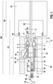
- Figure 1 shows a schematic cross section of a connector arrangement 100.
- the connector arrangement 100 has a connector 50 and a mating connector 60 which can be plugged together with the connector 50.
- the connector 50 has a housing 51 with a contact chamber 52 and a contact element 1 arranged in the contact chamber 52.
- the mating connector 60 has a mating connector housing 61, which is designed like a cup, and a mating contact element 62 arranged in the mating connector housing 61.
- the mating contact element 62 can be designed, for example, in the form of a flat contact blade or a pin or a round contact.
- a radial seal 63 is arranged on a side of the mating connector housing 61 facing the connector 50, which seals when the connectors are plugged together. 50 and mating connector 60 seal the common interior of the connector arrangement 100 against the ingress of dirt and moisture.
- the contact element 1 is suitable for inserting the counter contact element 62 along an insertion direction E.
- the contact element 1 has an insertion opening 2 for inserting the counter contact element 62.
- the contact element 1 also has at least one contact blade 3 for electrically contacting the counter contact element 62. In the cross section of the Fig. 1 two contact blades 3 can be seen. In principle, however, exactly one contact blade 3 or more than two contact blades 3 can be provided.
- the contact element 1 also has a clamping sleeve 4 which can be displaced along the insertion direction E relative to the at least one contact blade 3 between a first position P1 and a second position P2.
- the clamping sleeve 4 and the at least one contact blade 3 are operatively related to one another in such a way that when the clamping sleeve 4 is displaced from the first position P1 to the second position P2, the at least one contact blade 3 is displaced in a radial direction R perpendicular to the insertion direction E, e.g. radially inwards.
- the clamping sleeve 4 has a run-on element 5, which in a projection along the insertion direction E through the insertion opening 2 at least partially covers the insertion opening 2, so that when the counter-contact element 62 is inserted into the contact element 1, the counter-contact element 62 abuts the run-on element 5 (see Figs. 2b , 3b and 3c ) and upon further insertion of the counter contact element 62, the clamping sleeve 4 is displaced by means of the run-up element 5 in the direction of the second position P2.
- the clamping sleeve 4 can be made from a sheet metal, for example.
- the overrun element 5 can be bent radially inwards and protrude into the insertion path of the counter contact element 62 in the manner of a shield.
- the insertion opening 2 is in Fig. 1 through an opening in the housing 51 of the connector 50. If the contact element 1 is considered alone, the insertion opening 2 can be provided by the front end of the at least one contact blade 3 ( Figs. 2a-3c ).
- the clamping sleeve 4 has a first section 7 extending obliquely radially inwards in a front region 6 facing the counter-contact element 62. In the front region, a diameter D of the clamping sleeve 4 decreases from a first diameter D1 to a second diameter D2.
- the first section 7 of the clamping sleeve 4 is followed by a second section 8 which runs essentially parallel to the insertion direction E.
- the diameter D of the clamping sleeve 4 is constant, in the present Fig. 1 this is the second diameter D2.
- the clamping sleeve 4 can, for example, be fixed to the contact element 1 in a captive manner and can be displaced at the same time.
- a link structure can be provided on the contact element 1, for example, which specifies the possible displacement path of the clamping sleeve 4.
- the contact element 1 has Fig. 1 a contact box 35 which surrounds the contact blades 3.
- the contact blades 3 can be cut out of the contact box 35, for example.
- the contact box 35 can also be designed as a box into which the contact blades 3 are inserted or folded into.
- a front contact region 30 viewed along the insertion direction E, is followed by a front contact region 30, a central section 31 and a fastening section 32 for fastening an electrical line or a cable 40.
- the cable 40 has an electrical conductor 42 and insulation 41 which surrounds the conductor 42.
- an insulation crimp 37 and a line crimp 38 are provided here as an example (each shown schematically in dashed lines), although other types of fastening (e.g. soldering, welding, etc.) are also possible.
- the insulation crimp 37 is used to fix the insulation 41 of the cable in the fastening section 32
- the line crimp 38 is used to mechanically fasten the electrical conductor 42 to the contact element 1 and electrically connect it.
- This locking lance 9 can latch into a housing undercut 53 of the housing 51 of the connector 50, so that the contact element 1 is arranged in the contact chamber 52 of the housing 51 in a way that prevents it from being lost - it is then latched into the contact chamber 52.
- an inverse arrangement is also possible, i.e.: an undercut arranged on the contact element 1 in which a housing locking lance arranged on the housing 51 latches.
- the contact box 35 can also be formed by the two contact blades 3. Likewise, the locking lance 9 can be cut out of a contact blade 3.
- An ensemble consisting of the contact element 1 and the mating contact element 62 can also be referred to as a contact arrangement 70, in particular when the mating contact element 62 is inserted into the contact element 1.
- Fig. 1 it is clearly visible that the contact blades 3 are spaced apart from the counter-contact element 62 in the radial direction R as long as the clamping sleeve 4 is in the first position P1.
- Fig. 1 In addition to the insertion direction E, the radial direction R is specified as well as a circumferential direction U surrounding the insertion direction.
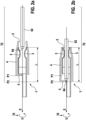
- Figure 2a shows a - simplified - schematic cross-section of a contact element 1 with the clamping sleeve 4 in the first position P1.
- the counter contact element 62 is still in front of the insertion opening 2 or is just passing through it.
- the insertion opening 2 is defined here by the front end of the contact blades 3.
- the counter contact element 62 is thus at the beginning of the plug-in path and thus at the beginning of a defined length L of the plug-in path. This plug-in path is completed here when the counter contact element 62 is completely inserted, i.e. is in a final plug-in position.
- Fig. 2a the contact element 1 is shown without a contact box 35 surrounding the contact blades 3.
- the box formed by the contact blades 3 could also be regarded as a contact box 35.
- Figure 2b shows a schematic cross-section of the contact element 1 from Fig. 2a with the inserted counter contact element 62 in the final plug-in position or final plug-in position and the clamping sleeve 4 in the second position P2.
- the counter contact element 62 with its free end 64 or with its tip has hit the run-up element 5 during the insertion process after approximately 75% of the defined length L of the insertion path.
- the run-up element 5 has dragged or taken the clamping sleeve 4 along the insertion path and thus displaced it relative to the contact blades 3 from the first position P1 to the second position P2.
- the run-up element 5 and the clamping sleeve 4 are operatively connected, e.g. by a relatively rigid coupling or in such a way that the run-up element 5 is only slightly tilted relative to its rest position when the counter contact element 62 hits the run-up element 5.
- the contact blades 3 By moving the clamping sleeve 4 into the second position P2, the contact blades 3 come into contact with an inner wall of the clamping sleeve 4 in its first section 7, in which the diameter D of the clamping sleeve 4 is reduced. As a result, the contact blades 3 are deflected radially inwards and thus pressed against the counter-contact element 62 towards the end of the plug-in path. Shortly before the end of the defined length L of the plug-in path, the diameter D of the clamping sleeve then remains constant in its second section 8, so that the set contact force also remains constant.
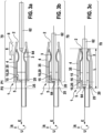
- Figure 3a shows a schematic cross-section of another contact element 1 with the clamping sleeve 4 in the first position P1.
- the locking lance 9 is not shown for reasons of clarity.
- the contact element 1 from Fig. 3a differs from that of Fig. 2a in that a first securing element 10 and a second securing element 10 are formed, arranged or provided on the clamping sleeve 4.
- Figure 3b shows a state in which the counter contact element 61 is inserted into the contact element 1 and is just abutting against the contact element 5 of the contact element 1, with the clamping sleeve 4 still in the first position P1.
- Figure 3c shows the contact element 1 with the inserted counter contact element 61 in the final plug-in position and with the clamping sleeve 4 in the second position P2.
- the first securing element 10 is designed as a type of latching hook. This latching hook engages behind a first undercut 15 of the contact box 35 when or as long as the clamping sleeve 4 is in the first position P1. The first securing element 10 thus prevents the clamping sleeve 4 from being accidentally moved from the first position P1 towards the second position P2 when no counter-contact element 62 is inserted into the contact element 1.
- Fig. 3a It can be seen that the first securing element 10 is operatively connected to the overrun element 5.
- the first securing element 10, which is designed as a latching hook only by way of example, is designed in one piece with the overrun element 5. It projects approximately parallel to the insertion direction E from the overrun element 5 in the direction of the insertion opening 2, the latching hook being formed at the free end of the first securing element 10 and projecting radially outwards.
- the second securing element 20 is intended to prevent a displacement of the clamping sleeve 4 from the second position P2 towards the first position P1 when the clamping sleeve 4 is in the second position P2, see Fig. 3c .
- the second securing element 20 is present twice here.
- Fig. 3a A radially inwardly directed locking hook is formed on the lower part of the clamping sleeve 4 at the end facing away from the insertion opening 2. This can be formed, for example, by bending the clamping sleeve 4 radially inward.
- Fig. 3a In the lower contact blade 3, a second recess 25 is provided in the area of the second position P2, into which this second securing element 20, designed as a latching hook, can engage when the clamping sleeve reaches the second position P2 ( Fig. 3c ).
- the first securing element 10 serves only as an example at the same time as the second securing element 20.
- the contact element 5 can be deflected elastically reversibly in the direction of the insertion direction E by the counter-contact element 61 when it hits in the manner of a spring.
- the overrun element 5 can spring back into its rest position ( Fig. 3c ).
- the locking hook of the first securing element 10 can catch the end of the Fig. 3a upper contact plate 3 and thus prevent unintentional relocation of the clamping sleeve 4 from the second position P2 into the first position P1.
- the first safety element 10 can also have a dual function as the second safety element 20.
- each securing element serves either only as the first securing element 10 or only as the second securing element 20.
- Figure 3b shows that when the counter-contact element 62 abuts against the run-on element 5, the latter is tilted slightly along the insertion direction E. This releases the first securing element 10, which is designed as a latching hook. This is because the latching hook tilts out of the first undercut 15. As a result, the clamping sleeve 4 can be displaced from the first position P1 towards the second position P2 by further moving the counter-contact element 62 along the insertion direction E.
- the clamping sleeve 4 can be moved from the second position P2 to the first position P1, whereby the contact blades 3 are released again from the front area 6 of the clamping sleeve and spring radially outwards. As a result, they are removed or released from the counter-contact element 62 and this can then be removed from the contact element 1 (almost) force-free.
- the clamping sleeve is moved from the second position P2 to the first position P1, the counter-contact element 62 can already be taken in the direction of the insertion opening, e.g. by means of the run-up element 5.
- the contact element 1 or the contact arrangement 70 or the connector 50 or the connector arrangement 100 is or can be intended or suitable or designed for use in motor vehicles or in inverters, motors, control units, batteries, chargers or generators.
- the contact element 1 or the contact arrangement 70 or the Connector 50 or connector assembly 100 is not limited to such applications or uses.
Landscapes
- Connector Housings Or Holding Contact Members (AREA)
- Details Of Connecting Devices For Male And Female Coupling (AREA)
Claims (11)
- Élément de contact pour insérer un élément de contact complémentaire (62) le long d'une direction d'insertion (E), l'élément de contact (1) présentant :-- une ouverture d'insertion (2) pour insérer l'élément de contact complémentaire (62) ;-- au moins une lamelle de contact (3) pour établir un contact électrique avec l'élément de contact complémentaire (62) ;-- un manchon de serrage (4) qui peut être déplacé le long de la direction d'insertion (E) par rapport à l'au moins une lamelle de contact (3) entre une première position (P1) et une deuxième position (P2) ;dans lequel le manchon de serrage (4) et l'au moins une lamelle de contact (3) sont en relation active l'un avec l'autre de telle sorte que, lors du déplacement du manchon de serrage (4) de la première position (P1) à la deuxième position (P2), l'au moins une lamelle de contact (3) est déplacée radialement vers l'intérieur dans une direction radiale (R) perpendiculaire à la direction d'insertion (E) ;dans lequel le manchon de serrage (4) présente un élément d'arrivée (5) qui, dans une projection le long de la direction d'insertion (E) à travers l'ouverture d'insertion (2), recouvre au moins partiellement l'ouverture d'insertion (2), de telle sorte que, lors de l'insertion de l'élément de contact complémentaire (62) dans l'élément de contact (1), l'élément de contact complémentaire (62) vient buter contre l'élément d'arrivée (5) et, lors de la poursuite de l'insertion de l'élément de contact complémentaire (62), le manchon de serrage (4) est déplacé en direction de la deuxième position (P2) au moyen de l'élément d'arrivée (5),dans lequel un premier élément de sécurité (10) est prévu sur le manchon de serrage (4), lequel empêche un déplacement du manchon de serrage (4) de la première position (P1) en direction de la deuxième position (P2) lorsqu'aucun élément de contact complémentaire (62) n'est inséré dans l'élément de contact (1).
- Élément de contact selon la revendication 1,dans lequel le manchon de serrage (4) présente, dans une zone avant (6) tournée vers l'élément de contact complémentaire (62), une première section (7) s'étendant obliquement radialement vers l'intérieur,dans laquelle, notamment, le diamètre (D) du manchon de serrage (4) diminue.
- Élément de contact selon la revendication précédente,dans lequel une deuxième section (8), qui s'étend parallèlement à la direction d'insertion (E), se raccorde à la première section (7) du manchon de serrage (4), en observant à l'encontre de la direction d'insertion (E),dans laquelle, notamment, le diamètre (D) du manchon de serrage (4) est constant.
- Élément de contact selon l'une quelconque des revendications précédentes, dans lequel le premier élément de sécurité (10) est relié fonctionnellement à l'élément d'arrivée (5).
- Élément de contact selon l'une quelconque des revendications précédentes, dans lequel un deuxième élément de sécurité (20) est prévu sur le manchon de serrage (4), lequel empêche un déplacement du manchon de serrage (4) de la deuxième position (P2) en direction de la première position (P1) lorsque le manchon de serrage (4) se trouve dans la deuxième position (P2).
- Élément de contact selon l'une quelconque des revendications précédentes, dans lequel une contre-dépouille est prévue sur l'élément de contact (1) pour l'encliquetage de l'élément de contact (1) dans une chambre de contact (52) d'un connecteur enfichable (50) et/ou
dans lequel une lance d'encliquetage (9), notamment pouvant être déviée de manière élastique et réversible, est prévue sur l'élément de contact (1) pour encliqueter l'élément de contact (1) dans une chambre de contact (52) d'un connecteur enfichable (50). - Agencement de contact comprenant :-- un élément de contact (1) selon l'une quelconque des revendications précédentes ;-- un élément de contact complémentaire (62) qui est inséré dans l'élément de contact (1) le long de la direction d'insertion (E).
- Agencement de contact selon la revendication précédente,
dans lequel l'au moins une lamelle de contact (3) ne touche pas l'élément de contact complémentaire (62) au moins tant que l'élément de contact complémentaire (62) ne vient pas en butée contre l'élément d'arrivée (5) lorsque l'élément de contact complémentaire (62) est inséré dans l'élément de contact (1) le long de la direction d'insertion (E). - Agencement de contact selon l'une quelconque des deux revendications précédentes,
dans lequel l'au moins une lamelle de contact (3) s'appuie sur l'élément de contact complémentaire (62) avec une force définie transversalement à la direction d'insertion (E) lorsque le manchon de serrage (4) se trouve dans la deuxième position (P2). - Connecteur enfichable, présentant :- un boîtier (51) avec une chambre de contact (52) ;-- un élément de contact (1) selon l'une quelconque des revendications 1 à 6 agencé dans la chambre de contact (52), l'élément de contact (1) étant notamment encliqueté dans la chambre de contact (52).
- Agencement de connecteur enfichable, présentant :- un connecteur enfichable (50) selon la revendication précédente ;-- un connecteur enfichable complémentaire (60)-- avec un boîtier de connecteur enfichable complémentaire (61)-- avec un élément de contact complémentaire (62) ;dans lequel le manchon de serrage (4) est déplacé dans la deuxième position (P2) au moyen de l'élément de contact complémentaire (62) à l'état complètement assemblé du connecteur enfichable (50) et du connecteur enfichable complémentaire (60),dans lequel, notamment, l'au moins une lamelle de contact (3) s'appuie sur l'élément de contact complémentaire (62) avec une force définie transversalement à la direction d'insertion (E).
Applications Claiming Priority (2)
| Application Number | Priority Date | Filing Date | Title |
|---|---|---|---|
| DE102019210695.1A DE102019210695B3 (de) | 2019-07-19 | 2019-07-19 | Kontaktelement |
| PCT/EP2020/066888 WO2021013442A1 (fr) | 2019-07-19 | 2020-06-18 | Élément de contact |
Publications (2)
| Publication Number | Publication Date |
|---|---|
| EP4000139A1 EP4000139A1 (fr) | 2022-05-25 |
| EP4000139B1 true EP4000139B1 (fr) | 2024-10-02 |
Family
ID=71108615
Family Applications (1)
| Application Number | Title | Priority Date | Filing Date |
|---|---|---|---|
| EP20733771.8A Active EP4000139B1 (fr) | 2019-07-19 | 2020-06-18 | Élément de contact |
Country Status (6)
| Country | Link |
|---|---|
| US (1) | US12308590B2 (fr) |
| EP (1) | EP4000139B1 (fr) |
| JP (1) | JP7326580B2 (fr) |
| DE (1) | DE102019210695B3 (fr) |
| ES (1) | ES3001460T3 (fr) |
| WO (1) | WO2021013442A1 (fr) |
Families Citing this family (4)
| Publication number | Priority date | Publication date | Assignee | Title |
|---|---|---|---|---|
| DE102019133032A1 (de) | 2019-12-04 | 2021-08-12 | Te Connectivity Germany Gmbh | Elektrische Kleinkraft-Kontakteinrichtung sowie elektrischer Kleinkraft-Verbinder |
| JP7560803B2 (ja) * | 2021-03-17 | 2024-10-03 | 株式会社オートネットワーク技術研究所 | コネクタ |
| DE102022212777A1 (de) * | 2022-11-29 | 2024-05-29 | Robert Bosch Gesellschaft mit beschränkter Haftung | Steckverbinderanordnung und Steckverbinder |
| EP4586414A1 (fr) * | 2024-01-11 | 2025-07-16 | ZF CV Systems Global GmbH | Connecteur électrique haute tension, ensemble de contact, câble de connexion et véhicule |
Citations (1)
| Publication number | Priority date | Publication date | Assignee | Title |
|---|---|---|---|---|
| EP1764875A1 (fr) * | 2005-09-14 | 2007-03-21 | Robert Bosch Gmbh | Connecteur électrique avec des contacts précontrainte |
Family Cites Families (13)
| Publication number | Priority date | Publication date | Assignee | Title |
|---|---|---|---|---|
| AT182150B (de) * | 1952-11-11 | 1955-05-25 | Rudolf Bogenschuetz Gmbh Elekt | Anordnung an Messerkontakten von Sicherungen |
| JPS62150875U (fr) | 1986-03-17 | 1987-09-24 | ||
| DE8907845U1 (de) * | 1989-06-27 | 1989-08-24 | Siemens AG, 1000 Berlin und 8000 München | Andruckstellverbinder |
| JPH0449488U (fr) | 1990-08-30 | 1992-04-27 | ||
| US6368129B1 (en) * | 1999-12-24 | 2002-04-09 | Delta Electronics, Inc. | Electrical connector with outer and inner sleeves |
| US6644995B1 (en) * | 2002-08-05 | 2003-11-11 | Hon Hai Precision Ind. Co., Ltd. | Low insertion force electrical connector |
| DE102005043693A1 (de) * | 2005-09-14 | 2007-03-15 | Robert Bosch Gmbh | Elektrischer Steckverbinder mit einer vorgespannten Kontaktlamelle |
| DE102005062889A1 (de) * | 2005-12-29 | 2007-07-05 | Robert Bosch Gmbh | Elektrische Null-Kraft-Steckvorrichtung |
| DE102012002145A1 (de) * | 2012-02-04 | 2013-08-08 | Kostal Kontakt Systeme Gmbh | Hülsenkontakt für einen elektrischen Nullkraftsteckverbinder |
| DE102012015568B4 (de) * | 2012-08-08 | 2018-12-20 | Auto-Kabel Management Gmbh | Steckverbinder |
| DE102013225513A1 (de) * | 2013-05-29 | 2014-12-04 | Tyco Electronics Amp Gmbh | Anordnung zur elektrischen Kontaktierung und Steckverbindung umfassend eine solche Anordnung, und Verfahren zum Zusammenstecken einer solchen Anordnung mit einer Gegenanordnung |
| JP6372675B1 (ja) * | 2017-12-14 | 2018-08-15 | Smk株式会社 | カードエッジ接続装置 |
| US10454203B2 (en) * | 2018-03-06 | 2019-10-22 | Te Connectivity Corporation | Receptacle connector of an electrical connector system |
-
2019
- 2019-07-19 DE DE102019210695.1A patent/DE102019210695B3/de not_active Expired - Fee Related
-
2020
- 2020-06-18 WO PCT/EP2020/066888 patent/WO2021013442A1/fr not_active Ceased
- 2020-06-18 ES ES20733771T patent/ES3001460T3/es active Active
- 2020-06-18 EP EP20733771.8A patent/EP4000139B1/fr active Active
- 2020-06-18 JP JP2022503580A patent/JP7326580B2/ja active Active
- 2020-06-18 US US17/625,396 patent/US12308590B2/en active Active
Patent Citations (1)
| Publication number | Priority date | Publication date | Assignee | Title |
|---|---|---|---|---|
| EP1764875A1 (fr) * | 2005-09-14 | 2007-03-21 | Robert Bosch Gmbh | Connecteur électrique avec des contacts précontrainte |
Also Published As
| Publication number | Publication date |
|---|---|
| WO2021013442A1 (fr) | 2021-01-28 |
| US20220271459A1 (en) | 2022-08-25 |
| JP7326580B2 (ja) | 2023-08-15 |
| ES3001460T3 (en) | 2025-03-05 |
| JP2022541300A (ja) | 2022-09-22 |
| EP4000139A1 (fr) | 2022-05-25 |
| US12308590B2 (en) | 2025-05-20 |
| DE102019210695B3 (de) | 2020-10-08 |
Similar Documents
| Publication | Publication Date | Title |
|---|---|---|
| EP2690716B1 (fr) | Elément de raccordement électrique | |
| DE102007004067B4 (de) | Steckverbinder | |
| EP3937313B1 (fr) | Connecteur à fiches électrique | |
| DE69709271T2 (de) | Elektrischer Steckverbinder für Kabel, Montage und dazugehörige Methode | |
| EP4066325B1 (fr) | Appareil de verrouillage secondaire | |
| EP3259810B1 (fr) | Connecteur avec un élément amortisseur | |
| EP1901402A1 (fr) | Connecteur solaire doté de moyens d'encliquetage améliorés | |
| DE102019210695B3 (de) | Kontaktelement | |
| EP3895256B1 (fr) | Connecteur enfichable rond présentant un dispositif de verrouillage | |
| EP2559112B1 (fr) | Élément de connexion enfichable électrique et pièce de connexion enfichable comportant plusieurs éléments de connexion enfichable | |
| EP2559110B1 (fr) | Dispositif de connexion électrique d'un câble, en particulier pièce de connexion enfichable avec un élément de contact au blindage | |
| EP2559105B1 (fr) | Dispositif de connexion électrique d'un câble, en particulier pièce de connexion enfichable | |
| EP3713018A1 (fr) | Connecteur enfichable électrique, fixation secondaire et procédé de montage d'un connecteur enfichable électrique | |
| EP2780986B1 (fr) | Connexion enfichable | |
| DE102018212135A1 (de) | Elektrischer Verbinder | |
| EP1936755B1 (fr) | Connecteur comportant une prise et une douille avec un support de contacts et une collerette de protection | |
| EP2031707A2 (fr) | Elément de connecteur à fiches électrique | |
| EP3288121A1 (fr) | Connecteur enfichable entièrement hermétique doté des forces de rétention améliorées | |
| DE102020110647A1 (de) | Primärverriegelung | |
| EP1641086B1 (fr) | Connecteur coaxial | |
| DE102020126541B4 (de) | Elektrischer Stecker und Fixiervorrichtung zur Fixierung eines Kontaktelements in einem Gehäuse des elektrischen Steckers | |
| EP4544644B1 (fr) | Ensemble boîtier de connecteur et connecteur | |
| EP2200127B1 (fr) | Agencement de connecteur à fiches | |
| EP1764874B1 (fr) | Connecteur électrique avec lame de contact précontraint | |
| DE202020005530U1 (de) | Primärverriegelung |
Legal Events
| Date | Code | Title | Description |
|---|---|---|---|
| STAA | Information on the status of an ep patent application or granted ep patent |
Free format text: STATUS: UNKNOWN |
|
| STAA | Information on the status of an ep patent application or granted ep patent |
Free format text: STATUS: THE INTERNATIONAL PUBLICATION HAS BEEN MADE |
|
| PUAI | Public reference made under article 153(3) epc to a published international application that has entered the european phase |
Free format text: ORIGINAL CODE: 0009012 |
|
| STAA | Information on the status of an ep patent application or granted ep patent |
Free format text: STATUS: REQUEST FOR EXAMINATION WAS MADE |
|
| 17P | Request for examination filed |
Effective date: 20220221 |
|
| AK | Designated contracting states |
Kind code of ref document: A1 Designated state(s): AL AT BE BG CH CY CZ DE DK EE ES FI FR GB GR HR HU IE IS IT LI LT LU LV MC MK MT NL NO PL PT RO RS SE SI SK SM TR |
|
| DAV | Request for validation of the european patent (deleted) | ||
| DAX | Request for extension of the european patent (deleted) | ||
| GRAP | Despatch of communication of intention to grant a patent |
Free format text: ORIGINAL CODE: EPIDOSNIGR1 |
|
| STAA | Information on the status of an ep patent application or granted ep patent |
Free format text: STATUS: GRANT OF PATENT IS INTENDED |
|
| RIC1 | Information provided on ipc code assigned before grant |
Ipc: H01R 4/50 20060101ALN20240422BHEP Ipc: H01R 13/11 20060101ALI20240422BHEP Ipc: H01R 13/193 20060101AFI20240422BHEP |
|
| INTG | Intention to grant announced |
Effective date: 20240510 |
|
| GRAS | Grant fee paid |
Free format text: ORIGINAL CODE: EPIDOSNIGR3 |
|
| GRAA | (expected) grant |
Free format text: ORIGINAL CODE: 0009210 |
|
| STAA | Information on the status of an ep patent application or granted ep patent |
Free format text: STATUS: THE PATENT HAS BEEN GRANTED |
|
| AK | Designated contracting states |
Kind code of ref document: B1 Designated state(s): AL AT BE BG CH CY CZ DE DK EE ES FI FR GB GR HR HU IE IS IT LI LT LU LV MC MK MT NL NO PL PT RO RS SE SI SK SM TR |
|
| REG | Reference to a national code |
Ref country code: GB Ref legal event code: FG4D Free format text: NOT ENGLISH |
|
| REG | Reference to a national code |
Ref country code: CH Ref legal event code: EP |
|
| REG | Reference to a national code |
Ref country code: DE Ref legal event code: R096 Ref document number: 502020009374 Country of ref document: DE |
|
| REG | Reference to a national code |
Ref country code: IE Ref legal event code: FG4D Free format text: LANGUAGE OF EP DOCUMENT: GERMAN |
|
| REG | Reference to a national code |
Ref country code: LT Ref legal event code: MG9D |
|
| REG | Reference to a national code |
Ref country code: NL Ref legal event code: MP Effective date: 20241002 |
|
| PG25 | Lapsed in a contracting state [announced via postgrant information from national office to epo] |
Ref country code: NL Free format text: LAPSE BECAUSE OF FAILURE TO SUBMIT A TRANSLATION OF THE DESCRIPTION OR TO PAY THE FEE WITHIN THE PRESCRIBED TIME-LIMIT Effective date: 20241002 |
|
| PG25 | Lapsed in a contracting state [announced via postgrant information from national office to epo] |
Ref country code: NL Free format text: LAPSE BECAUSE OF FAILURE TO SUBMIT A TRANSLATION OF THE DESCRIPTION OR TO PAY THE FEE WITHIN THE PRESCRIBED TIME-LIMIT Effective date: 20241002 |
|
| PG25 | Lapsed in a contracting state [announced via postgrant information from national office to epo] |
Ref country code: PT Free format text: LAPSE BECAUSE OF FAILURE TO SUBMIT A TRANSLATION OF THE DESCRIPTION OR TO PAY THE FEE WITHIN THE PRESCRIBED TIME-LIMIT Effective date: 20250203 Ref country code: HR Free format text: LAPSE BECAUSE OF FAILURE TO SUBMIT A TRANSLATION OF THE DESCRIPTION OR TO PAY THE FEE WITHIN THE PRESCRIBED TIME-LIMIT Effective date: 20241002 Ref country code: IS Free format text: LAPSE BECAUSE OF FAILURE TO SUBMIT A TRANSLATION OF THE DESCRIPTION OR TO PAY THE FEE WITHIN THE PRESCRIBED TIME-LIMIT Effective date: 20250202 |
|
| PG25 | Lapsed in a contracting state [announced via postgrant information from national office to epo] |
Ref country code: FI Free format text: LAPSE BECAUSE OF FAILURE TO SUBMIT A TRANSLATION OF THE DESCRIPTION OR TO PAY THE FEE WITHIN THE PRESCRIBED TIME-LIMIT Effective date: 20241002 |
|
| PG25 | Lapsed in a contracting state [announced via postgrant information from national office to epo] |
Ref country code: BG Free format text: LAPSE BECAUSE OF FAILURE TO SUBMIT A TRANSLATION OF THE DESCRIPTION OR TO PAY THE FEE WITHIN THE PRESCRIBED TIME-LIMIT Effective date: 20241002 |
|
| PG25 | Lapsed in a contracting state [announced via postgrant information from national office to epo] |
Ref country code: NO Free format text: LAPSE BECAUSE OF FAILURE TO SUBMIT A TRANSLATION OF THE DESCRIPTION OR TO PAY THE FEE WITHIN THE PRESCRIBED TIME-LIMIT Effective date: 20250102 |
|
| PG25 | Lapsed in a contracting state [announced via postgrant information from national office to epo] |
Ref country code: GR Free format text: LAPSE BECAUSE OF FAILURE TO SUBMIT A TRANSLATION OF THE DESCRIPTION OR TO PAY THE FEE WITHIN THE PRESCRIBED TIME-LIMIT Effective date: 20250103 Ref country code: LV Free format text: LAPSE BECAUSE OF FAILURE TO SUBMIT A TRANSLATION OF THE DESCRIPTION OR TO PAY THE FEE WITHIN THE PRESCRIBED TIME-LIMIT Effective date: 20241002 |
|
| PG25 | Lapsed in a contracting state [announced via postgrant information from national office to epo] |
Ref country code: CZ Free format text: LAPSE BECAUSE OF FAILURE TO SUBMIT A TRANSLATION OF THE DESCRIPTION OR TO PAY THE FEE WITHIN THE PRESCRIBED TIME-LIMIT Effective date: 20241002 Ref country code: PL Free format text: LAPSE BECAUSE OF FAILURE TO SUBMIT A TRANSLATION OF THE DESCRIPTION OR TO PAY THE FEE WITHIN THE PRESCRIBED TIME-LIMIT Effective date: 20241002 |
|
| PG25 | Lapsed in a contracting state [announced via postgrant information from national office to epo] |
Ref country code: RS Free format text: LAPSE BECAUSE OF FAILURE TO SUBMIT A TRANSLATION OF THE DESCRIPTION OR TO PAY THE FEE WITHIN THE PRESCRIBED TIME-LIMIT Effective date: 20250102 |
|
| PG25 | Lapsed in a contracting state [announced via postgrant information from national office to epo] |
Ref country code: SM Free format text: LAPSE BECAUSE OF FAILURE TO SUBMIT A TRANSLATION OF THE DESCRIPTION OR TO PAY THE FEE WITHIN THE PRESCRIBED TIME-LIMIT Effective date: 20241002 |
|
| REG | Reference to a national code |
Ref country code: DE Ref legal event code: R097 Ref document number: 502020009374 Country of ref document: DE |
|
| PG25 | Lapsed in a contracting state [announced via postgrant information from national office to epo] |
Ref country code: DK Free format text: LAPSE BECAUSE OF FAILURE TO SUBMIT A TRANSLATION OF THE DESCRIPTION OR TO PAY THE FEE WITHIN THE PRESCRIBED TIME-LIMIT Effective date: 20241002 |
|
| PGFP | Annual fee paid to national office [announced via postgrant information from national office to epo] |
Ref country code: GB Payment date: 20250620 Year of fee payment: 6 |
|
| PG25 | Lapsed in a contracting state [announced via postgrant information from national office to epo] |
Ref country code: EE Free format text: LAPSE BECAUSE OF FAILURE TO SUBMIT A TRANSLATION OF THE DESCRIPTION OR TO PAY THE FEE WITHIN THE PRESCRIBED TIME-LIMIT Effective date: 20241002 |
|
| PGFP | Annual fee paid to national office [announced via postgrant information from national office to epo] |
Ref country code: FR Payment date: 20250626 Year of fee payment: 6 |
|
| PG25 | Lapsed in a contracting state [announced via postgrant information from national office to epo] |
Ref country code: RO Free format text: LAPSE BECAUSE OF FAILURE TO SUBMIT A TRANSLATION OF THE DESCRIPTION OR TO PAY THE FEE WITHIN THE PRESCRIBED TIME-LIMIT Effective date: 20241002 |
|
| PG25 | Lapsed in a contracting state [announced via postgrant information from national office to epo] |
Ref country code: SK Free format text: LAPSE BECAUSE OF FAILURE TO SUBMIT A TRANSLATION OF THE DESCRIPTION OR TO PAY THE FEE WITHIN THE PRESCRIBED TIME-LIMIT Effective date: 20241002 |
|
| PLBE | No opposition filed within time limit |
Free format text: ORIGINAL CODE: 0009261 |
|
| STAA | Information on the status of an ep patent application or granted ep patent |
Free format text: STATUS: NO OPPOSITION FILED WITHIN TIME LIMIT |
|
| PG25 | Lapsed in a contracting state [announced via postgrant information from national office to epo] |
Ref country code: SE Free format text: LAPSE BECAUSE OF FAILURE TO SUBMIT A TRANSLATION OF THE DESCRIPTION OR TO PAY THE FEE WITHIN THE PRESCRIBED TIME-LIMIT Effective date: 20241002 |
|
| 26N | No opposition filed |
Effective date: 20250703 |
|
| PGFP | Annual fee paid to national office [announced via postgrant information from national office to epo] |
Ref country code: ES Payment date: 20250718 Year of fee payment: 6 |
|
| PGFP | Annual fee paid to national office [announced via postgrant information from national office to epo] |
Ref country code: DE Payment date: 20250814 Year of fee payment: 6 |
|
| PGFP | Annual fee paid to national office [announced via postgrant information from national office to epo] |
Ref country code: IT Payment date: 20250630 Year of fee payment: 6 |
|
| REG | Reference to a national code |
Ref country code: CH Ref legal event code: H13 Free format text: ST27 STATUS EVENT CODE: U-0-0-H10-H13 (AS PROVIDED BY THE NATIONAL OFFICE) Effective date: 20260127 |
|
| PG25 | Lapsed in a contracting state [announced via postgrant information from national office to epo] |
Ref country code: MC Free format text: LAPSE BECAUSE OF FAILURE TO SUBMIT A TRANSLATION OF THE DESCRIPTION OR TO PAY THE FEE WITHIN THE PRESCRIBED TIME-LIMIT Effective date: 20241002 |
|
| PG25 | Lapsed in a contracting state [announced via postgrant information from national office to epo] |
Ref country code: LU Free format text: LAPSE BECAUSE OF NON-PAYMENT OF DUE FEES Effective date: 20250618 |
|
| REG | Reference to a national code |
Ref country code: BE Ref legal event code: MM Effective date: 20250630 |
|
| PG25 | Lapsed in a contracting state [announced via postgrant information from national office to epo] |
Ref country code: IE Free format text: LAPSE BECAUSE OF NON-PAYMENT OF DUE FEES Effective date: 20250618 |
|
| PG25 | Lapsed in a contracting state [announced via postgrant information from national office to epo] |
Ref country code: BE Free format text: LAPSE BECAUSE OF NON-PAYMENT OF DUE FEES Effective date: 20250630 |
|
| PG25 | Lapsed in a contracting state [announced via postgrant information from national office to epo] |
Ref country code: CH Free format text: LAPSE BECAUSE OF NON-PAYMENT OF DUE FEES Effective date: 20250630 |