EP2092633B1 - Antriebssteuervorrichtung und verfahren für einen lüftermotor des kühlschranktyps - Google Patents
Antriebssteuervorrichtung und verfahren für einen lüftermotor des kühlschranktyps Download PDFInfo
- Publication number
- EP2092633B1 EP2092633B1 EP07833215.2A EP07833215A EP2092633B1 EP 2092633 B1 EP2092633 B1 EP 2092633B1 EP 07833215 A EP07833215 A EP 07833215A EP 2092633 B1 EP2092633 B1 EP 2092633B1
- Authority
- EP
- European Patent Office
- Prior art keywords
- fan motor
- fan
- unit
- driving
- fan motors
- Prior art date
- Legal status (The legal status is an assumption and is not a legal conclusion. Google has not performed a legal analysis and makes no representation as to the accuracy of the status listed.)
- Not-in-force
Links
- 238000000034 method Methods 0.000 title claims description 15
- 238000007710 freezing Methods 0.000 claims description 28
- 230000008014 freezing Effects 0.000 claims description 28
- 238000001514 detection method Methods 0.000 claims description 4
- 239000003985 ceramic capacitor Substances 0.000 claims description 3
- 239000003990 capacitor Substances 0.000 description 4
- NTKSJAPQYKCFPP-UHFFFAOYSA-N 1,2,4,5-tetrachloro-3-(3-chlorophenyl)benzene Chemical compound ClC1=CC=CC(C=2C(=C(Cl)C=C(Cl)C=2Cl)Cl)=C1 NTKSJAPQYKCFPP-UHFFFAOYSA-N 0.000 description 2
- 238000010276 construction Methods 0.000 description 2
- 238000010586 diagram Methods 0.000 description 2
- 101100365087 Arabidopsis thaliana SCRA gene Proteins 0.000 description 1
- 238000001816 cooling Methods 0.000 description 1
- 230000008878 coupling Effects 0.000 description 1
- 238000010168 coupling process Methods 0.000 description 1
- 238000005859 coupling reaction Methods 0.000 description 1
- 230000007812 deficiency Effects 0.000 description 1
- 230000003111 delayed effect Effects 0.000 description 1
- 230000000694 effects Effects 0.000 description 1
- 239000012212 insulator Substances 0.000 description 1
- 230000007257 malfunction Effects 0.000 description 1
- 239000000463 material Substances 0.000 description 1
- 238000000465 moulding Methods 0.000 description 1
- 210000002445 nipple Anatomy 0.000 description 1
- 239000004033 plastic Substances 0.000 description 1
- 230000001012 protector Effects 0.000 description 1
- 239000012815 thermoplastic material Substances 0.000 description 1
- 229920005992 thermoplastic resin Polymers 0.000 description 1
- XLYOFNOQVPJJNP-UHFFFAOYSA-N water Substances O XLYOFNOQVPJJNP-UHFFFAOYSA-N 0.000 description 1
Images


Classifications
-
- H—ELECTRICITY
- H02—GENERATION; CONVERSION OR DISTRIBUTION OF ELECTRIC POWER
- H02P—CONTROL OR REGULATION OF ELECTRIC MOTORS, ELECTRIC GENERATORS OR DYNAMO-ELECTRIC CONVERTERS; CONTROLLING TRANSFORMERS, REACTORS OR CHOKE COILS
- H02P27/00—Arrangements or methods for the control of AC motors characterised by the kind of supply voltage
- H02P27/02—Arrangements or methods for the control of AC motors characterised by the kind of supply voltage using supply voltage with constant frequency and variable amplitude
-
- F—MECHANICAL ENGINEERING; LIGHTING; HEATING; WEAPONS; BLASTING
- F25—REFRIGERATION OR COOLING; COMBINED HEATING AND REFRIGERATION SYSTEMS; HEAT PUMP SYSTEMS; MANUFACTURE OR STORAGE OF ICE; LIQUEFACTION SOLIDIFICATION OF GASES
- F25D—REFRIGERATORS; COLD ROOMS; ICE-BOXES; COOLING OR FREEZING APPARATUS NOT OTHERWISE PROVIDED FOR
- F25D17/00—Arrangements for circulating cooling fluids; Arrangements for circulating gas, e.g. air, within refrigerated spaces
- F25D17/04—Arrangements for circulating cooling fluids; Arrangements for circulating gas, e.g. air, within refrigerated spaces for circulating air, e.g. by convection
- F25D17/06—Arrangements for circulating cooling fluids; Arrangements for circulating gas, e.g. air, within refrigerated spaces for circulating air, e.g. by convection by forced circulation
- F25D17/062—Arrangements for circulating cooling fluids; Arrangements for circulating gas, e.g. air, within refrigerated spaces for circulating air, e.g. by convection by forced circulation in household refrigerators
- F25D17/065—Arrangements for circulating cooling fluids; Arrangements for circulating gas, e.g. air, within refrigerated spaces for circulating air, e.g. by convection by forced circulation in household refrigerators with compartments at different temperatures
-
- H—ELECTRICITY
- H02—GENERATION; CONVERSION OR DISTRIBUTION OF ELECTRIC POWER
- H02P—CONTROL OR REGULATION OF ELECTRIC MOTORS, ELECTRIC GENERATORS OR DYNAMO-ELECTRIC CONVERTERS; CONTROLLING TRANSFORMERS, REACTORS OR CHOKE COILS
- H02P1/00—Arrangements for starting electric motors or dynamo-electric converters
- H02P1/16—Arrangements for starting electric motors or dynamo-electric converters for starting dynamo-electric motors or dynamo-electric converters
- H02P1/54—Arrangements for starting electric motors or dynamo-electric converters for starting dynamo-electric motors or dynamo-electric converters for starting two or more dynamo-electric motors
- H02P1/58—Arrangements for starting electric motors or dynamo-electric converters for starting dynamo-electric motors or dynamo-electric converters for starting two or more dynamo-electric motors sequentially
-
- H—ELECTRICITY
- H02—GENERATION; CONVERSION OR DISTRIBUTION OF ELECTRIC POWER
- H02P—CONTROL OR REGULATION OF ELECTRIC MOTORS, ELECTRIC GENERATORS OR DYNAMO-ELECTRIC CONVERTERS; CONTROLLING TRANSFORMERS, REACTORS OR CHOKE COILS
- H02P7/00—Arrangements for regulating or controlling the speed or torque of electric DC motors
- H02P7/06—Arrangements for regulating or controlling the speed or torque of electric DC motors for regulating or controlling an individual DC dynamo-electric motor by varying field or armature current
-
- F—MECHANICAL ENGINEERING; LIGHTING; HEATING; WEAPONS; BLASTING
- F25—REFRIGERATION OR COOLING; COMBINED HEATING AND REFRIGERATION SYSTEMS; HEAT PUMP SYSTEMS; MANUFACTURE OR STORAGE OF ICE; LIQUEFACTION SOLIDIFICATION OF GASES
- F25D—REFRIGERATORS; COLD ROOMS; ICE-BOXES; COOLING OR FREEZING APPARATUS NOT OTHERWISE PROVIDED FOR
- F25D2317/00—Details or arrangements for circulating cooling fluids; Details or arrangements for circulating gas, e.g. air, within refrigerated spaces, not provided for in other groups of this subclass
- F25D2317/06—Details or arrangements for circulating cooling fluids; Details or arrangements for circulating gas, e.g. air, within refrigerated spaces, not provided for in other groups of this subclass with forced air circulation
- F25D2317/068—Details or arrangements for circulating cooling fluids; Details or arrangements for circulating gas, e.g. air, within refrigerated spaces, not provided for in other groups of this subclass with forced air circulation characterised by the fans
- F25D2317/0681—Details thereof
-
- F—MECHANICAL ENGINEERING; LIGHTING; HEATING; WEAPONS; BLASTING
- F25—REFRIGERATION OR COOLING; COMBINED HEATING AND REFRIGERATION SYSTEMS; HEAT PUMP SYSTEMS; MANUFACTURE OR STORAGE OF ICE; LIQUEFACTION SOLIDIFICATION OF GASES
- F25D—REFRIGERATORS; COLD ROOMS; ICE-BOXES; COOLING OR FREEZING APPARATUS NOT OTHERWISE PROVIDED FOR
- F25D2317/00—Details or arrangements for circulating cooling fluids; Details or arrangements for circulating gas, e.g. air, within refrigerated spaces, not provided for in other groups of this subclass
- F25D2317/06—Details or arrangements for circulating cooling fluids; Details or arrangements for circulating gas, e.g. air, within refrigerated spaces, not provided for in other groups of this subclass with forced air circulation
- F25D2317/068—Details or arrangements for circulating cooling fluids; Details or arrangements for circulating gas, e.g. air, within refrigerated spaces, not provided for in other groups of this subclass with forced air circulation characterised by the fans
- F25D2317/0682—Two or more fans
-
- F—MECHANICAL ENGINEERING; LIGHTING; HEATING; WEAPONS; BLASTING
- F25—REFRIGERATION OR COOLING; COMBINED HEATING AND REFRIGERATION SYSTEMS; HEAT PUMP SYSTEMS; MANUFACTURE OR STORAGE OF ICE; LIQUEFACTION SOLIDIFICATION OF GASES
- F25D—REFRIGERATORS; COLD ROOMS; ICE-BOXES; COOLING OR FREEZING APPARATUS NOT OTHERWISE PROVIDED FOR
- F25D2323/00—General constructional features not provided for in other groups of this subclass
- F25D2323/002—Details for cooling refrigerating machinery
- F25D2323/0023—Control of the air flow cooling refrigerating machinery
-
- F—MECHANICAL ENGINEERING; LIGHTING; HEATING; WEAPONS; BLASTING
- F25—REFRIGERATION OR COOLING; COMBINED HEATING AND REFRIGERATION SYSTEMS; HEAT PUMP SYSTEMS; MANUFACTURE OR STORAGE OF ICE; LIQUEFACTION SOLIDIFICATION OF GASES
- F25D—REFRIGERATORS; COLD ROOMS; ICE-BOXES; COOLING OR FREEZING APPARATUS NOT OTHERWISE PROVIDED FOR
- F25D2323/00—General constructional features not provided for in other groups of this subclass
- F25D2323/002—Details for cooling refrigerating machinery
- F25D2323/0028—Details for cooling refrigerating machinery characterised by the fans
- F25D2323/00281—Two or more fans
-
- H—ELECTRICITY
- H02—GENERATION; CONVERSION OR DISTRIBUTION OF ELECTRIC POWER
- H02P—CONTROL OR REGULATION OF ELECTRIC MOTORS, ELECTRIC GENERATORS OR DYNAMO-ELECTRIC CONVERTERS; CONTROLLING TRANSFORMERS, REACTORS OR CHOKE COILS
- H02P6/00—Arrangements for controlling synchronous motors or other dynamo-electric motors using electronic commutation dependent on the rotor position; Electronic commutators therefor
- H02P6/14—Electronic commutators
- H02P6/16—Circuit arrangements for detecting position
- H02P6/18—Circuit arrangements for detecting position without separate position detecting elements
- H02P6/182—Circuit arrangements for detecting position without separate position detecting elements using back-emf in windings
Definitions
- the present invention relates to an apparatus and method for controlling driving of a fan motor for a refrigerator, and more particularly, to an apparatus and method for controlling driving of a fan motor for a refrigerator capable of improving operation efficiency of a plurality of fan motors installed in the refrigerator by sequentially operating the plurality of fan motors at certain delay times.
- a cool air supplying fan motor assembly is installed within a refrigerator in order to supply cool air in the refrigerator.
- an inner rotor type BLDC motor having a magnet rotor within a stator is used as the cool air supplying fan motor.
- the cool air supplying fan motor can hardly accomplish high efficiency because a fan load is mounted at an inner rotor-type motor or an axial flow fan motor is employed, and because the size is increased in an axial direction and in a radial direction of the motor, the cool air supplying fan motor assembly cannot become compact, resulting in a problem in that the capacity of the refrigerator cannot be increased.
- a control method includes the steps of (a) determining whether or not a plurality of air blast devices, respectively connected to a plurality of storage chambers, and a compressor are respectively in starting conditions; (b) in case that it is determined that at least two air blast devices and the compressor are in the starting conditions, turning a part of the at least two air blast devices in the starting condition and the compressor on; and (c) turning all of the air blast devices in the starting condition on after a designated time from the turning-on of the air blast device elapses.
- US 2002/043946 A1 describes an apparatus for controlling a cooling fan for a vehicle.
- a filter circuit which is constructed by capacitors and a reactor, is provided to suppress passage of a current flowing in a positive power supply line and a negative power supply line to a battery via power source terminals in association with switching of an inverter circuit.
- US 2002/0144510 A1 describes a method for controlling a power saving operation of a refrigerator with two evaporators. Operation of at least any one of a freezing chamber evaporator fan, a refrigerating chamber evaporator fan, or a condenser fan is extended or delayed, as necessary.
- WO 2005/067131 A1 describes a method for driving a brushless DC motor comprising a step for rectifying the AC voltage of an AC power supply through a rectifier circuit having a capacitor connected between the output terminals and receiving the AC voltage of the AC power supply.
- JP S55-133690 A relates to sequentially starting a plurality of motors when power is restored after power failure during the operation of the motors.
- a first timer is energized.
- a first motor is energized.
- a second motor M2 is driven.
- Other motors are also sequentially driven.
- the possibility of voltage drop and generation of operation deficiency can be reduced to thus improve operation efficiency with respect to the plurality of fan motors.
- a single MLCC Multilayer Ceramic Capacitor
- MLCC Multilayer Ceramic Capacitor
- a fan motor to which the apparatus and method for controlling driving of a fan motor for a refrigerator according to the present invention is applied, is a device configured by integrally molding a stator and a printed circuit board (PCB) with a thermoplastic material to thus accomplish a compact cool air supplying fan motor assembly.
- PCB printed circuit board
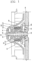
- FIG. 1 is a vertical sectional view showing a cool air supplying fan motor assembly according to the present invention
- FIG. 2 is a view illustrating a major part in FIG. 1 .
- the cool air supplying fan motor assembly 100 includes a stator 11 with a coil 113 wound thereon; a mold type stator assembly 110 configured such that a PCB 112 is integrally molded and connected with one side of the stator 111; a bearing assembly 120 inserted at a central portion of the stator assembly 110; a permanent magnet 130 positioned at an outer side of the stator assembly 110; and a fan 150 including a shaft 140 inserted to be rotatable at a central portion of the bearing assembly 120 and fixed at one side of the permanent magnet 130.
- the stator assembly 110 is made of a thermoplastic resin, e.g., micromelt.
- a protrusion 110a is formed at one face of the stator assembly 110a, by which a foreign material such as water can be prevented from infiltrating into the stator assembly 110 from an outer side of the motor.
- the PCB 112 includes a 3-phase drive IC 112a and an MLCC (Multilayer Ceramic Capacitor) 112b.
- MLCC Multilayer Ceramic Capacitor
- a hub 151 is formed at an inner central portion of the fan 150, and an outer diameter of the permanent magnet 130 is inserted into the inner diameter of the hub 151.
- the permanent magnet 130 is fixed at the hub 151 of the fan 150, and in this case, preferably, a bonding process is used.
- a shaft base 141 is fixed at one end portion of the shaft 140 such that the end portion of the shaft 140 may protrude, and the a nipple 152 is formed at a central portion of the fan 150 into which the end of the shaft 140 is inserted. Accordingly, the shaft 140 is inserted into the hub 151 of the fan 150, and the shaft 140 is firmly fixed in the fan 150.
- the bearing assembly 120 includes a first bearing assembly 121 positioned at the side of the fan 150 and a second bearing assembly 122 positioned at the opposite side of the fan 150.
- a felt 121 b is positioned within a housing 121a, and a bearing 121c, which contacts with the shaft 140, is installed at a central portion of the felt 121 b.
- a felt 122b is positioned within a housing 122a, and a bearing 122c, which contacts with the shaft 140, is installed at a central portion of the felt 122b.
- the permanent magnet 130 is a plastic magnet, is parlyene-coated, and anisotropic-magnetized.
- Reference numeral 122c denotes a coupling recess
- 142 denotes a stop ring inserted into the end of the shaft 140
- 115 denotes an insulator
- 160 denotes a motor mount plate that supports a motor
- 'C' denotes cable
- 143 denotes an oil protector.
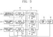
- FIG. 3 is a schematic block diagram showing the construction of an apparatus for controlling driving of a fan motor used for a refrigerator according to an embodiment of the present invention.
- the apparatus for controlling driving of a fan motor for a refrigerator includes a refrigerating chamber fan motor 10, a freezing chamber fan motor 20, a mechanic chamber fan motor 30, a driving unit 40, a control unit 60, a power unit 70, and cutoff unit 50.
- the fan motors 10, 20 and 30 may be additionally configured according to the size or characteristics of the refrigerator. For example, when two fan motors can be used for the refrigerating chamber or two fan motor may be additionally used for the freezing chamber. Accordingly, more driving units may be used to drive the respective fan motors. However, basically, there is no problem in applying the present invention in which the respective fan motors are sequentially controlled at certain time intervals.
- the refrigerating chamber fan motor 10 supplies cool air to a refrigerating chamber.
- the freezing chamber fan motor 20 supplies cool air to a freezing chamber.
- the mechanic chamber fan motor 30 lowers temperature of a compressor (not shown) by circulating air in a mechanic chamber.
- the driving unit 40 generates drive signals for driving the refrigerating chamber fan motor 10, the freezing chamber fan motor 20 and the mechanic chamber fan motor 30.
- the driving unit 40 includes a first driving unit 41 that drives the refrigerating chamber fan motor 10, a second driving unit 42 that drives the freezing chamber fan motor 20, and a third driving unit 43 that drives the mechanic chamber fan motor 30.
- the first driving unit 41 detects a position of a rotor with a counter electromotive force of the refrigerating chamber fan motor, and drives the refrigerating chamber fan motor according to the detection result.
- the second driving unit 42 detects a position of the rotor with a counter electromotive force of the freezing chamber fan motor and drives the freezing chamber fan motor according to the detection result.
- the third driving unit 43 detects a position of the rotor with a counter electromotive force of the mechanic chamber fan motor and drives the mechanic chamber fan motor according to the detection result.
- the control unit 60 controls the operations of the first, the second, and the third driving units 41, 42, and 43 such that the refrigerating chamber fan motor 10, the freezing chamber fan motor 20 and the mechanic chamber fan motor 30 are sequentially operated at certain delay times.
- the cutoff unit 50 is positioned between the driving unit 40 and the power unit 70 and cuts off noise and a surge voltage generated from the power unit 70.
- the cutoff unit 50 includes a first filter 51 that removes noise and a surge voltage and smoothes voltage applied to the first driving unit 41, a second filter 52 that removes noise and a surge voltage and smoothes voltage applied to the second driving unit 42, and a third filter 53 that removes noise and a surge voltage and smoothes voltage applied to the third driving unit 43.
- a single large capacity MLCC instead of a noise reducing bypass capacitor, is used as the first, the second, and the third filters 51, 52 and 53.
- control unit 60 checks whether or not a fan motor operation command for supplying cool air in the refrigerator is inputted (SP10).
- the control unit 60 applies control signals for driving the refrigerating chamber fan motor 10, the freezing chamber fan motor 20 and the mechanic chamber fan motor 30 to the driving unit 40 (SP11 ⁇ SP15).
- control unit 60 sequentially generates the control signals for driving the refrigerating chamber fan motor 10, the freezing chamber fan motor 20 and the mechanic chamber fan motor 30 at certain delay time intervals (about one second, but not limited thereto and it can be variably set by less than or more than the delay time one second according to characteristics of each element).
- the operation order of the refrigerating chamber fan motor 10, the freezing chamber fan motor 20 and the mechanic chamber fan motor 30 may be previously set, and any type of combinations may be used.
- the refrigerating chamber fan motor 10, the freezing chamber fan motor 20, the mechanic chamber fan motor 30 may be operated in sequence at certain delay times.
- the refrigerating chamber fan motor 10, the mechanic chamber fan motor 30 and the freezing chamber fan motor 20 may be operated in sequence at certain delay times.
- the freezing chamber fan motor 20, the refrigerating chamber fan motor 10, the mechanic chamber fan motor 30 may be operated in sequence at certain delay times.
- the freezing chamber fan motor 20, the mechanic chamber fan motor 30 and the refrigerating chamber fan motor 10 may be operated in sequence at certain delay times.
- the mechanic chamber fan motor 30, the refrigerating chamber fan motor 10 and the freezing chamber fan motor 20 may be operated in sequence at certain delay times.
- the mechanic chamber fan motor 30, the freezing chamber fan motor 20 and the refrigerating chamber fan motor 10 may be operated in sequence at certain delay times.
- the driving unit 40 sequentially outputs drive signals for driving the refrigerating chamber fan motor 10, the freezing chamber fan motor 20 and the mechanic chamber fan motor 30 at certain delay times according to the control signals (e.g., operating in the order of the refrigerating chamber fan motor, the freezing chamber fan motor and the mechanic chamber fan motor) outputted from the control unit 60.
- control signals e.g., operating in the order of the refrigerating chamber fan motor, the freezing chamber fan motor and the mechanic chamber fan motor
- the first driving unit 41 outputs a first drive signal for driving the refrigerating chamber fan motor 10 under the control of the control unit 60
- the second driving unit 42 outputs a second driver signal for driving the freezing chamber fan motor 20 under the control of the control unit 60
- the third driving unit 43 outputs a third drive signal for driving the mechanic chamber fan motor 30 under the control of the control unit 60.
- the refrigerating chamber fan motor 10 is operated by the first drive signal, and after a certain time (about one second), the freezing chamber fan motor 20 is operated by the second drive signal, and after a certain time (about one second), the mechanic chamber fan motor 30 is operated by the third drive signal.
- the power unit 70 supplies operation power to the driving unit 40, the control unit 60, the refrigerating chamber fan motor 10, the freezing chamber fan motor 20 and the mechanic chamber fan motor 30.
- the power unit 70 supplies power, noise and a surge voltage may be generated from the power.
- EMI noise may be generated due to external power.
- a bypass capacitor is provided between the power unit 70 and the control unit 60, but in the present invention, the cutoff unit 50 for cutting off noise, a surge voltage and external EMI noise is provided between the power unit 70 and the control unit 60.
- the cutoff unit 50 removes noise and a surge voltage, and includes the first, the second and the third filters 51, 52 and 53 that smooth the voltage applied to the driving unit 40.
- the first, the second and the third filters 51, 52 and 53 include the MLCC.
- the plurality of fan motors provided in the refrigerator are sequentially operated at certain delay times to thus improve the operation efficiency of the plurality of fan motors, and removing noise and the surge voltage by using the single MLCC.
Landscapes
- Engineering & Computer Science (AREA)
- Power Engineering (AREA)
- Chemical & Material Sciences (AREA)
- Combustion & Propulsion (AREA)
- Physics & Mathematics (AREA)
- Mechanical Engineering (AREA)
- Thermal Sciences (AREA)
- General Engineering & Computer Science (AREA)
- Cold Air Circulating Systems And Constructional Details In Refrigerators (AREA)
- Devices That Are Associated With Refrigeration Equipment (AREA)
Claims (7)
- Vorrichtung, die konfiguriert ist, das Antreiben eines Gebläsemotors, der für einen Kühlschrank verwendet wird, zu steuern, wobei die Vorrichtung umfasst:einen Kühlkammer-Gebläsemotor (10), der dafür ausgelegt ist, einer Kühlklammer Kühlluft zuzuführen,einen Gefrierkammer-Gebläsemotor (20), der dafür ausgelegt ist, einer Gefrierkammer Kühlluft zuzuführen, undeinen Mechanikkammer-Gebläsemotor (30), der konfiguriert ist, die Luft in einer Mechanikkammer zirkulieren zu lassen;eine Antriebseinheit (40), die konfiguriert ist, die Antriebssignale zum Antreiben der mehreren Gebläsemotoren (10, 20, 30) zu erzeugen;eine Steuereinheit (60), die konfiguriert ist, den Betrieb der Antriebseinheit (40) zu steuern; undeine Leistungseinheit (70), die konfiguriert ist, der Antriebseinheit (40) und der Steuereinheit (60) Betriebsleistung bereitzustellen;gekennzeichnet durcheine Sperreinheit (50), die zwischen der Antriebseinheit (40) und der Leistungseinheit (70) positioniert ist und konfiguriert ist, das Rauschen und eine Stoßspannung, die von der Leistungseinheit (70) zu der Antriebseinheit (40) eingeleitet wird, zu sperren;wobei die Steuereinheit (60) konfiguriert ist, die mehreren Gebläsemotoren (10, 20, 30) mit bestimmten Verzögerungszeiten gemäß einer im Voraus festgelegten Reihenfolge sequentiell zu betreiben, wenn ein Betriebsbefehl eingegeben wird, wobei dann, wenn ein erster der Gebläsemotoren (10, 20, 30) betrieben wird, ein zweiter der Gebläsemotoren (10, 20, 30) folgen soll, nachdem eine bestimmte Verzögerungszeit vergangen ist, und dann, wenn der zweite der Gebläsemotoren (10, 20, 30) betrieben wird, ein dritter der Gebläsemotoren (10, 20, 30) folgen soll, nachdem eine bestimmte Verzögerungszeit vergangen ist, wobei die bestimmten Verzögerungszeiten vorher festgelegt werden.
- Vorrichtung nach Anspruch 1, wobei die Antriebseinheit (40) mehrere Antriebseinheiten (41, 42, 43) umfasst, die die jeweiligen Gebläsemotoren (10, 20, 30) antreiben.
- Vorrichtung nach Anspruch 2, wobei die Antriebseinheit (40) dafür ausgelegt ist, eine Position eines Rotors jedes Gebläsemotors (10, 20, 30) zu detektieren und jeden Gebläsemotor (10, 20, 30) gemäß dem Detektionsergebnis anzutreiben.
- Vorrichtung nach Anspruch 1, wobei die Sperreinheit (50) ein oder mehrere Filter (51, 52, 53) umfasst, die dafür ausgelegt sind, das Rauschen und eine von der Leistungseinheit (70) erzeugte Stoßspannung zu entfernen und die an jede Antriebseinheit (40) angelegte Spannung zu glätten.
- Vorrichtung nach Anspruch 4, wobei das eine oder die mehreren Filter (51, 52, 53) wenigstens einen MLCC (Mehrschicht-Keramikkondensator) umfassen.
- Vorrichtung nach Anspruch 1, wobei die vorgegebenen Zeitverzögerungen bis auf mehr als eine Sekunde variabel gesetzt werden.
- Verfahren zum Steuern mehrerer Gebläsemotoren, die für einen Kühlschrank verwendet werden, wobei das Verfahren Folgendes umfasst:Bestimmen, ob ein Betriebsbefehl eingegeben wird,dadurch gekennzeichnet, dass das Verfahren ferner umfasst:sequentielles Betreiben der mehreren Gebläsemotoren einschließlich eines Kühlkammer-Gebläsemotors (10), der dafür ausgelegt ist, einer Kühlkammer Kühlluft zuzuführen, eines Gefrierkammer-Gebläsemotors (20), der dafür ausgelegt ist, einer Gefrierkammer Kühlluft zuzuführen, und eines Mechanikkammer-Gebläsemotors (30), der dafür ausgelegt ist, die Luft in einer Mechanikkammer zirkulieren zu lassen, gemäß einer im Voraus festgelegten Reihenfolge mit bestimmten Verzögerungszeiten, um Kühlluft zuzuführen oder die Luft innerhalb des Kühlschranks zirkulieren zu lassen, wenn der Betriebsbefehl eingegeben wird,wobei dann, wenn ein erster der Gebläsemotoren (10, 20, 30) betrieben wird, ein zweiter der Gebläsemotoren (10, 20, 30) folgen soll, nachdem eine bestimmte Verzögerungszeit vergangen ist, und dann, wenn der zweite der Gebläsemotoren (10, 20, 30) betrieben wird, ein dritter der Gebläsemotoren (10, 20, 30) folgen soll, nachdem eine bestimmte Verzögerungszeit vergangen ist, wobei die bestimmten Verzögerungszeiten vorher festgelegt werden.
Applications Claiming Priority (2)
| Application Number | Priority Date | Filing Date | Title |
|---|---|---|---|
| KR1020060131217A KR101285614B1 (ko) | 2006-12-20 | 2006-12-20 | 냉장고용 팬모터의 구동제어장치 및 방법 |
| PCT/KR2007/004904 WO2008075828A1 (en) | 2006-12-20 | 2007-10-08 | Drive control apparatus and method for refrigerator type fan motor |
Publications (3)
| Publication Number | Publication Date |
|---|---|
| EP2092633A1 EP2092633A1 (de) | 2009-08-26 |
| EP2092633A4 EP2092633A4 (de) | 2014-03-12 |
| EP2092633B1 true EP2092633B1 (de) | 2017-03-29 |
Family
ID=39536428
Family Applications (1)
| Application Number | Title | Priority Date | Filing Date |
|---|---|---|---|
| EP07833215.2A Not-in-force EP2092633B1 (de) | 2006-12-20 | 2007-10-08 | Antriebssteuervorrichtung und verfahren für einen lüftermotor des kühlschranktyps |
Country Status (6)
| Country | Link |
|---|---|
| US (1) | US8341972B2 (de) |
| EP (1) | EP2092633B1 (de) |
| KR (1) | KR101285614B1 (de) |
| CN (1) | CN101569087B (de) |
| ES (1) | ES2628291T3 (de) |
| WO (1) | WO2008075828A1 (de) |
Families Citing this family (3)
| Publication number | Priority date | Publication date | Assignee | Title |
|---|---|---|---|---|
| US8241008B2 (en) | 2009-02-26 | 2012-08-14 | Standard Microsystems Corporation | RPM controller using drive profiles |
| CN103883551B (zh) * | 2014-03-31 | 2016-01-20 | 国家电网公司 | 一种消除轴流风机喘振的控制方法 |
| CN105386992A (zh) * | 2015-12-08 | 2016-03-09 | 国网山东省电力公司电力科学研究院 | 一种基于风机出力动态平衡的优化控制系统及方法 |
Citations (1)
| Publication number | Priority date | Publication date | Assignee | Title |
|---|---|---|---|---|
| JPS55133690A (en) * | 1979-04-05 | 1980-10-17 | Mitsubishi Electric Corp | Start controller for motor |
Family Cites Families (14)
| Publication number | Priority date | Publication date | Assignee | Title |
|---|---|---|---|---|
| JP3720180B2 (ja) * | 1997-12-12 | 2005-11-24 | 三菱電機株式会社 | 冷蔵庫の運転制御方法および運転制御装置 |
| KR100319932B1 (ko) * | 1998-10-07 | 2002-04-22 | 장병우 | 전동기의과전압방지장치 |
| JP4048698B2 (ja) | 2000-07-28 | 2008-02-20 | 株式会社デンソー | 車両用冷却ファンの制御装置および制御方法 |
| JP4442006B2 (ja) * | 2000-08-23 | 2010-03-31 | 株式会社デンソー | 車両用冷却ファンの制御装置 |
| US6463893B1 (en) | 2000-10-31 | 2002-10-15 | Caterpillar Inc | Cooling fan drive system |
| US6883339B2 (en) * | 2001-04-04 | 2005-04-26 | Lg Electronics Inc. | Method for controlling power saving operation of refrigerator with two evaporator |
| JP2003219683A (ja) * | 2002-01-22 | 2003-07-31 | Fujitsu General Ltd | 永久磁石電動機の制御方法 |
| JP3861704B2 (ja) | 2002-01-31 | 2006-12-20 | 株式会社デンソー | 車両用冷却ファンモータの駆動装置 |
| KR20050056722A (ko) | 2003-12-10 | 2005-06-16 | 삼성전자주식회사 | 냉장고 및 그 제어 방법 |
| JP2005198376A (ja) * | 2004-01-05 | 2005-07-21 | Matsushita Electric Ind Co Ltd | ブラシレスdcモータの駆動方法およびその装置 |
| KR20050096338A (ko) * | 2004-03-30 | 2005-10-06 | 삼성전자주식회사 | 냉장고 및 그 제어방법 |
| KR100665059B1 (ko) * | 2004-12-01 | 2007-01-09 | 삼성전자주식회사 | 모터 구동 장치 |
| JP2006238626A (ja) | 2005-02-25 | 2006-09-07 | Toshiba Corp | 電気車用電力変換装置 |
| JP2006304444A (ja) * | 2005-04-19 | 2006-11-02 | Matsushita Electric Ind Co Ltd | モータ駆動装置と冷蔵庫 |
-
2006
- 2006-12-20 KR KR1020060131217A patent/KR101285614B1/ko not_active Expired - Fee Related
-
2007
- 2007-10-08 EP EP07833215.2A patent/EP2092633B1/de not_active Not-in-force
- 2007-10-08 US US12/518,542 patent/US8341972B2/en not_active Expired - Fee Related
- 2007-10-08 WO PCT/KR2007/004904 patent/WO2008075828A1/en not_active Ceased
- 2007-10-08 CN CN2007800478736A patent/CN101569087B/zh not_active Expired - Fee Related
- 2007-10-08 ES ES07833215.2T patent/ES2628291T3/es active Active
Patent Citations (1)
| Publication number | Priority date | Publication date | Assignee | Title |
|---|---|---|---|---|
| JPS55133690A (en) * | 1979-04-05 | 1980-10-17 | Mitsubishi Electric Corp | Start controller for motor |
Also Published As
| Publication number | Publication date |
|---|---|
| EP2092633A4 (de) | 2014-03-12 |
| US20100017039A1 (en) | 2010-01-21 |
| CN101569087B (zh) | 2013-09-04 |
| EP2092633A1 (de) | 2009-08-26 |
| US8341972B2 (en) | 2013-01-01 |
| ES2628291T3 (es) | 2017-08-02 |
| KR20080057648A (ko) | 2008-06-25 |
| WO2008075828A1 (en) | 2008-06-26 |
| CN101569087A (zh) | 2009-10-28 |
| KR101285614B1 (ko) | 2013-07-12 |
Similar Documents
| Publication | Publication Date | Title |
|---|---|---|
| EP2464915B1 (de) | Verdichter- und kondensatoranordnungen für hvac-systeme | |
| JP6530174B2 (ja) | 冷凍サイクル装置 | |
| JP6491455B2 (ja) | 電動機 | |
| US9479108B2 (en) | Electric compressor | |
| CN104254463B (zh) | 鼓风装置以及车辆中的鼓风装置的控制方法 | |
| CA2625503A1 (en) | Refrigeration system | |
| KR20040023546A (ko) | 압축기 구동장치 및 냉동 공기조절장치 | |
| JP6235381B2 (ja) | 圧縮機 | |
| US6525505B2 (en) | Device for driving an air-conditioning compressor | |
| EP2092633B1 (de) | Antriebssteuervorrichtung und verfahren für einen lüftermotor des kühlschranktyps | |
| JP2008271687A (ja) | 電力変換装置およびこれを用いたモータ駆動用インバータ制御装置 | |
| US10767650B2 (en) | Drive device for electric compressor | |
| JP2012159270A (ja) | 制御装置及びヒートポンプ装置 | |
| WO2015025475A1 (ja) | 電動圧縮機 | |
| EP2447535B1 (de) | Steuerung für einen motorbetriebenen Verdichter | |
| JP2018174630A (ja) | 車載用電動圧縮機 | |
| KR20130027856A (ko) | 전동 압축기의 제어방법 | |
| JP2006291878A (ja) | 電動圧縮機の制御方法および制御装置 | |
| KR100804958B1 (ko) | 냉장고용 압축기 모터 구동 제어방법 | |
| JP6830178B2 (ja) | 回路内蔵ブラシレスdcモータおよびそれを用いた熱交換型冷却機 | |
| JP2009250123A (ja) | 電動コンプレッサ | |
| JP2009203839A (ja) | 冷凍装置 | |
| GB2500297A (en) | Refrigeration power supply system, particularly for use in transport refrigeration |
Legal Events
| Date | Code | Title | Description |
|---|---|---|---|
| PUAI | Public reference made under article 153(3) epc to a published international application that has entered the european phase |
Free format text: ORIGINAL CODE: 0009012 |
|
| 17P | Request for examination filed |
Effective date: 20090515 |
|
| AK | Designated contracting states |
Kind code of ref document: A1 Designated state(s): AT BE BG CH CY CZ DE DK EE ES FI FR GB GR HU IE IS IT LI LT LU LV MC MT NL PL PT RO SE SI SK TR |
|
| DAX | Request for extension of the european patent (deleted) | ||
| A4 | Supplementary search report drawn up and despatched |
Effective date: 20140207 |
|
| RIC1 | Information provided on ipc code assigned before grant |
Ipc: F25D 17/06 20060101ALI20140203BHEP Ipc: H02P 6/18 20060101AFI20140203BHEP |
|
| 17Q | First examination report despatched |
Effective date: 20160330 |
|
| REG | Reference to a national code |
Ref country code: DE Ref legal event code: R079 Ref document number: 602007050425 Country of ref document: DE Free format text: PREVIOUS MAIN CLASS: H02P0027020000 Ipc: H02P0006180000 |
|
| GRAP | Despatch of communication of intention to grant a patent |
Free format text: ORIGINAL CODE: EPIDOSNIGR1 |
|
| RIC1 | Information provided on ipc code assigned before grant |
Ipc: H02P 1/58 20060101ALI20161007BHEP Ipc: H02P 6/18 20160101AFI20161007BHEP Ipc: H02P 6/182 20160101ALI20161007BHEP Ipc: F25D 17/06 20060101ALI20161007BHEP |
|
| INTG | Intention to grant announced |
Effective date: 20161028 |
|
| RAP1 | Party data changed (applicant data changed or rights of an application transferred) |
Owner name: LG ELECTRONICS INC. |
|
| GRAS | Grant fee paid |
Free format text: ORIGINAL CODE: EPIDOSNIGR3 |
|
| GRAA | (expected) grant |
Free format text: ORIGINAL CODE: 0009210 |
|
| AK | Designated contracting states |
Kind code of ref document: B1 Designated state(s): AT BE BG CH CY CZ DE DK EE ES FI FR GB GR HU IE IS IT LI LT LU LV MC MT NL PL PT RO SE SI SK TR |
|
| REG | Reference to a national code |
Ref country code: GB Ref legal event code: FG4D |
|
| REG | Reference to a national code |
Ref country code: CH Ref legal event code: EP |
|
| REG | Reference to a national code |
Ref country code: AT Ref legal event code: REF Ref document number: 880619 Country of ref document: AT Kind code of ref document: T Effective date: 20170415 |
|
| REG | Reference to a national code |
Ref country code: IE Ref legal event code: FG4D |
|
| REG | Reference to a national code |
Ref country code: DE Ref legal event code: R096 Ref document number: 602007050425 Country of ref document: DE |
|
| PG25 | Lapsed in a contracting state [announced via postgrant information from national office to epo] |
Ref country code: FI Free format text: LAPSE BECAUSE OF FAILURE TO SUBMIT A TRANSLATION OF THE DESCRIPTION OR TO PAY THE FEE WITHIN THE PRESCRIBED TIME-LIMIT Effective date: 20170329 Ref country code: GR Free format text: LAPSE BECAUSE OF FAILURE TO SUBMIT A TRANSLATION OF THE DESCRIPTION OR TO PAY THE FEE WITHIN THE PRESCRIBED TIME-LIMIT Effective date: 20170630 Ref country code: LT Free format text: LAPSE BECAUSE OF FAILURE TO SUBMIT A TRANSLATION OF THE DESCRIPTION OR TO PAY THE FEE WITHIN THE PRESCRIBED TIME-LIMIT Effective date: 20170329 |
|
| REG | Reference to a national code |
Ref country code: ES Ref legal event code: FG2A Ref document number: 2628291 Country of ref document: ES Kind code of ref document: T3 Effective date: 20170802 Ref country code: NL Ref legal event code: MP Effective date: 20170329 |
|
| REG | Reference to a national code |
Ref country code: AT Ref legal event code: MK05 Ref document number: 880619 Country of ref document: AT Kind code of ref document: T Effective date: 20170329 |
|
| PG25 | Lapsed in a contracting state [announced via postgrant information from national office to epo] |
Ref country code: BG Free format text: LAPSE BECAUSE OF FAILURE TO SUBMIT A TRANSLATION OF THE DESCRIPTION OR TO PAY THE FEE WITHIN THE PRESCRIBED TIME-LIMIT Effective date: 20170629 Ref country code: SE Free format text: LAPSE BECAUSE OF FAILURE TO SUBMIT A TRANSLATION OF THE DESCRIPTION OR TO PAY THE FEE WITHIN THE PRESCRIBED TIME-LIMIT Effective date: 20170329 Ref country code: LV Free format text: LAPSE BECAUSE OF FAILURE TO SUBMIT A TRANSLATION OF THE DESCRIPTION OR TO PAY THE FEE WITHIN THE PRESCRIBED TIME-LIMIT Effective date: 20170329 |
|
| REG | Reference to a national code |
Ref country code: FR Ref legal event code: PLFP Year of fee payment: 11 |
|
| PG25 | Lapsed in a contracting state [announced via postgrant information from national office to epo] |
Ref country code: NL Free format text: LAPSE BECAUSE OF FAILURE TO SUBMIT A TRANSLATION OF THE DESCRIPTION OR TO PAY THE FEE WITHIN THE PRESCRIBED TIME-LIMIT Effective date: 20170329 |
|
| PG25 | Lapsed in a contracting state [announced via postgrant information from national office to epo] |
Ref country code: SK Free format text: LAPSE BECAUSE OF FAILURE TO SUBMIT A TRANSLATION OF THE DESCRIPTION OR TO PAY THE FEE WITHIN THE PRESCRIBED TIME-LIMIT Effective date: 20170329 Ref country code: IT Free format text: LAPSE BECAUSE OF FAILURE TO SUBMIT A TRANSLATION OF THE DESCRIPTION OR TO PAY THE FEE WITHIN THE PRESCRIBED TIME-LIMIT Effective date: 20170329 Ref country code: CZ Free format text: LAPSE BECAUSE OF FAILURE TO SUBMIT A TRANSLATION OF THE DESCRIPTION OR TO PAY THE FEE WITHIN THE PRESCRIBED TIME-LIMIT Effective date: 20170329 Ref country code: AT Free format text: LAPSE BECAUSE OF FAILURE TO SUBMIT A TRANSLATION OF THE DESCRIPTION OR TO PAY THE FEE WITHIN THE PRESCRIBED TIME-LIMIT Effective date: 20170329 Ref country code: RO Free format text: LAPSE BECAUSE OF FAILURE TO SUBMIT A TRANSLATION OF THE DESCRIPTION OR TO PAY THE FEE WITHIN THE PRESCRIBED TIME-LIMIT Effective date: 20170329 Ref country code: EE Free format text: LAPSE BECAUSE OF FAILURE TO SUBMIT A TRANSLATION OF THE DESCRIPTION OR TO PAY THE FEE WITHIN THE PRESCRIBED TIME-LIMIT Effective date: 20170329 |
|
| PG25 | Lapsed in a contracting state [announced via postgrant information from national office to epo] |
Ref country code: PL Free format text: LAPSE BECAUSE OF FAILURE TO SUBMIT A TRANSLATION OF THE DESCRIPTION OR TO PAY THE FEE WITHIN THE PRESCRIBED TIME-LIMIT Effective date: 20170329 Ref country code: IS Free format text: LAPSE BECAUSE OF FAILURE TO SUBMIT A TRANSLATION OF THE DESCRIPTION OR TO PAY THE FEE WITHIN THE PRESCRIBED TIME-LIMIT Effective date: 20170729 Ref country code: PT Free format text: LAPSE BECAUSE OF FAILURE TO SUBMIT A TRANSLATION OF THE DESCRIPTION OR TO PAY THE FEE WITHIN THE PRESCRIBED TIME-LIMIT Effective date: 20170731 |
|
| REG | Reference to a national code |
Ref country code: DE Ref legal event code: R097 Ref document number: 602007050425 Country of ref document: DE |
|
| PG25 | Lapsed in a contracting state [announced via postgrant information from national office to epo] |
Ref country code: DK Free format text: LAPSE BECAUSE OF FAILURE TO SUBMIT A TRANSLATION OF THE DESCRIPTION OR TO PAY THE FEE WITHIN THE PRESCRIBED TIME-LIMIT Effective date: 20170329 |
|
| PLBE | No opposition filed within time limit |
Free format text: ORIGINAL CODE: 0009261 |
|
| STAA | Information on the status of an ep patent application or granted ep patent |
Free format text: STATUS: NO OPPOSITION FILED WITHIN TIME LIMIT |
|
| 26N | No opposition filed |
Effective date: 20180103 |
|
| PG25 | Lapsed in a contracting state [announced via postgrant information from national office to epo] |
Ref country code: SI Free format text: LAPSE BECAUSE OF FAILURE TO SUBMIT A TRANSLATION OF THE DESCRIPTION OR TO PAY THE FEE WITHIN THE PRESCRIBED TIME-LIMIT Effective date: 20170329 Ref country code: MC Free format text: LAPSE BECAUSE OF FAILURE TO SUBMIT A TRANSLATION OF THE DESCRIPTION OR TO PAY THE FEE WITHIN THE PRESCRIBED TIME-LIMIT Effective date: 20170329 |
|
| REG | Reference to a national code |
Ref country code: CH Ref legal event code: PL |
|
| REG | Reference to a national code |
Ref country code: IE Ref legal event code: MM4A |
|
| PG25 | Lapsed in a contracting state [announced via postgrant information from national office to epo] |
Ref country code: LU Free format text: LAPSE BECAUSE OF NON-PAYMENT OF DUE FEES Effective date: 20171008 Ref country code: LI Free format text: LAPSE BECAUSE OF NON-PAYMENT OF DUE FEES Effective date: 20171031 Ref country code: CH Free format text: LAPSE BECAUSE OF NON-PAYMENT OF DUE FEES Effective date: 20171031 |
|
| REG | Reference to a national code |
Ref country code: BE Ref legal event code: MM Effective date: 20171031 |
|
| PG25 | Lapsed in a contracting state [announced via postgrant information from national office to epo] |
Ref country code: BE Free format text: LAPSE BECAUSE OF NON-PAYMENT OF DUE FEES Effective date: 20171031 |
|
| REG | Reference to a national code |
Ref country code: FR Ref legal event code: PLFP Year of fee payment: 12 |
|
| PG25 | Lapsed in a contracting state [announced via postgrant information from national office to epo] |
Ref country code: MT Free format text: LAPSE BECAUSE OF NON-PAYMENT OF DUE FEES Effective date: 20171008 |
|
| PG25 | Lapsed in a contracting state [announced via postgrant information from national office to epo] |
Ref country code: IE Free format text: LAPSE BECAUSE OF NON-PAYMENT OF DUE FEES Effective date: 20171008 |
|
| PG25 | Lapsed in a contracting state [announced via postgrant information from national office to epo] |
Ref country code: HU Free format text: LAPSE BECAUSE OF FAILURE TO SUBMIT A TRANSLATION OF THE DESCRIPTION OR TO PAY THE FEE WITHIN THE PRESCRIBED TIME-LIMIT; INVALID AB INITIO Effective date: 20071008 |
|
| PG25 | Lapsed in a contracting state [announced via postgrant information from national office to epo] |
Ref country code: CY Free format text: LAPSE BECAUSE OF NON-PAYMENT OF DUE FEES Effective date: 20170329 |
|
| PG25 | Lapsed in a contracting state [announced via postgrant information from national office to epo] |
Ref country code: TR Free format text: LAPSE BECAUSE OF FAILURE TO SUBMIT A TRANSLATION OF THE DESCRIPTION OR TO PAY THE FEE WITHIN THE PRESCRIBED TIME-LIMIT Effective date: 20170329 |
|
| PGFP | Annual fee paid to national office [announced via postgrant information from national office to epo] |
Ref country code: FR Payment date: 20210913 Year of fee payment: 15 |
|
| PGFP | Annual fee paid to national office [announced via postgrant information from national office to epo] |
Ref country code: GB Payment date: 20220905 Year of fee payment: 16 |
|
| PGFP | Annual fee paid to national office [announced via postgrant information from national office to epo] |
Ref country code: ES Payment date: 20221114 Year of fee payment: 16 Ref country code: DE Payment date: 20220615 Year of fee payment: 16 |
|
| PG25 | Lapsed in a contracting state [announced via postgrant information from national office to epo] |
Ref country code: FR Free format text: LAPSE BECAUSE OF NON-PAYMENT OF DUE FEES Effective date: 20221031 |
|
| REG | Reference to a national code |
Ref country code: DE Ref legal event code: R119 Ref document number: 602007050425 Country of ref document: DE |
|
| GBPC | Gb: european patent ceased through non-payment of renewal fee |
Effective date: 20231008 |
|
| PG25 | Lapsed in a contracting state [announced via postgrant information from national office to epo] |
Ref country code: GB Free format text: LAPSE BECAUSE OF NON-PAYMENT OF DUE FEES Effective date: 20231008 |
|
| PG25 | Lapsed in a contracting state [announced via postgrant information from national office to epo] |
Ref country code: GB Free format text: LAPSE BECAUSE OF NON-PAYMENT OF DUE FEES Effective date: 20231008 Ref country code: DE Free format text: LAPSE BECAUSE OF NON-PAYMENT OF DUE FEES Effective date: 20240501 |
|
| REG | Reference to a national code |
Ref country code: ES Ref legal event code: FD2A Effective date: 20241128 |
|
| PG25 | Lapsed in a contracting state [announced via postgrant information from national office to epo] |
Ref country code: ES Free format text: LAPSE BECAUSE OF NON-PAYMENT OF DUE FEES Effective date: 20231009 |
|
| PG25 | Lapsed in a contracting state [announced via postgrant information from national office to epo] |
Ref country code: ES Free format text: LAPSE BECAUSE OF NON-PAYMENT OF DUE FEES Effective date: 20231009 |