EP2092696B1 - Réservation et admission de ressources d'accès pour une sélection d'accès dans des réseaux à multiples accès - Google Patents
Réservation et admission de ressources d'accès pour une sélection d'accès dans des réseaux à multiples accès Download PDFInfo
- Publication number
- EP2092696B1 EP2092696B1 EP07847166A EP07847166A EP2092696B1 EP 2092696 B1 EP2092696 B1 EP 2092696B1 EP 07847166 A EP07847166 A EP 07847166A EP 07847166 A EP07847166 A EP 07847166A EP 2092696 B1 EP2092696 B1 EP 2092696B1
- Authority
- EP
- European Patent Office
- Prior art keywords
- access
- access resource
- resource
- information
- entity
- Prior art date
- Legal status (The legal status is an assumption and is not a legal conclusion. Google has not performed a legal analysis and makes no representation as to the accuracy of the status listed.)
- Not-in-force
Links
- 238000000034 method Methods 0.000 claims description 55
- 238000012545 processing Methods 0.000 claims description 12
- 230000008569 process Effects 0.000 claims description 10
- 238000004590 computer program Methods 0.000 claims description 6
- 238000005259 measurement Methods 0.000 claims description 4
- 238000004891 communication Methods 0.000 description 69
- 230000006870 function Effects 0.000 description 36
- 238000010586 diagram Methods 0.000 description 25
- 230000000875 corresponding effect Effects 0.000 description 8
- 230000011664 signaling Effects 0.000 description 8
- 230000005540 biological transmission Effects 0.000 description 6
- 238000010187 selection method Methods 0.000 description 5
- 230000008901 benefit Effects 0.000 description 4
- 230000008859 change Effects 0.000 description 4
- 238000005516 engineering process Methods 0.000 description 3
- 238000013475 authorization Methods 0.000 description 2
- 230000002596 correlated effect Effects 0.000 description 2
- 230000001960 triggered effect Effects 0.000 description 2
- 229910000906 Bronze Inorganic materials 0.000 description 1
- 230000000903 blocking effect Effects 0.000 description 1
- 239000010974 bronze Substances 0.000 description 1
- 239000000969 carrier Substances 0.000 description 1
- 230000001413 cellular effect Effects 0.000 description 1
- 238000012790 confirmation Methods 0.000 description 1
- KUNSUQLRTQLHQQ-UHFFFAOYSA-N copper tin Chemical compound [Cu].[Sn] KUNSUQLRTQLHQQ-UHFFFAOYSA-N 0.000 description 1
- 230000007423 decrease Effects 0.000 description 1
- 230000003247 decreasing effect Effects 0.000 description 1
- 238000001514 detection method Methods 0.000 description 1
- 230000004069 differentiation Effects 0.000 description 1
- 239000000835 fiber Substances 0.000 description 1
- PCHJSUWPFVWCPO-UHFFFAOYSA-N gold Chemical compound [Au] PCHJSUWPFVWCPO-UHFFFAOYSA-N 0.000 description 1
- 229910052737 gold Inorganic materials 0.000 description 1
- 239000010931 gold Substances 0.000 description 1
- 230000007774 longterm Effects 0.000 description 1
- 238000010295 mobile communication Methods 0.000 description 1
- 238000012986 modification Methods 0.000 description 1
- 230000004048 modification Effects 0.000 description 1
- 238000012544 monitoring process Methods 0.000 description 1
- 230000006855 networking Effects 0.000 description 1
- 238000005457 optimization Methods 0.000 description 1
- 230000008707 rearrangement Effects 0.000 description 1
- 238000000926 separation method Methods 0.000 description 1
- 229910052709 silver Inorganic materials 0.000 description 1
- 239000004332 silver Substances 0.000 description 1
- 238000006467 substitution reaction Methods 0.000 description 1
Images






Classifications
-
- H—ELECTRICITY
- H04—ELECTRIC COMMUNICATION TECHNIQUE
- H04W—WIRELESS COMMUNICATION NETWORKS
- H04W28/00—Network traffic management; Network resource management
- H04W28/16—Central resource management; Negotiation of resources or communication parameters, e.g. negotiating bandwidth or QoS [Quality of Service]
-
- H—ELECTRICITY
- H04—ELECTRIC COMMUNICATION TECHNIQUE
- H04L—TRANSMISSION OF DIGITAL INFORMATION, e.g. TELEGRAPHIC COMMUNICATION
- H04L47/00—Traffic control in data switching networks
- H04L47/10—Flow control; Congestion control
- H04L47/15—Flow control; Congestion control in relation to multipoint traffic
-
- H—ELECTRICITY
- H04—ELECTRIC COMMUNICATION TECHNIQUE
- H04L—TRANSMISSION OF DIGITAL INFORMATION, e.g. TELEGRAPHIC COMMUNICATION
- H04L47/00—Traffic control in data switching networks
- H04L47/70—Admission control; Resource allocation
- H04L47/72—Admission control; Resource allocation using reservation actions during connection setup
-
- H—ELECTRICITY
- H04—ELECTRIC COMMUNICATION TECHNIQUE
- H04L—TRANSMISSION OF DIGITAL INFORMATION, e.g. TELEGRAPHIC COMMUNICATION
- H04L47/00—Traffic control in data switching networks
- H04L47/70—Admission control; Resource allocation
- H04L47/78—Architectures of resource allocation
- H04L47/788—Autonomous allocation of resources
-
- H—ELECTRICITY
- H04—ELECTRIC COMMUNICATION TECHNIQUE
- H04L—TRANSMISSION OF DIGITAL INFORMATION, e.g. TELEGRAPHIC COMMUNICATION
- H04L47/00—Traffic control in data switching networks
- H04L47/70—Admission control; Resource allocation
- H04L47/82—Miscellaneous aspects
- H04L47/822—Collecting or measuring resource availability data
-
- H—ELECTRICITY
- H04—ELECTRIC COMMUNICATION TECHNIQUE
- H04L—TRANSMISSION OF DIGITAL INFORMATION, e.g. TELEGRAPHIC COMMUNICATION
- H04L47/00—Traffic control in data switching networks
- H04L47/70—Admission control; Resource allocation
- H04L47/82—Miscellaneous aspects
- H04L47/824—Applicable to portable or mobile terminals
-
- H—ELECTRICITY
- H04—ELECTRIC COMMUNICATION TECHNIQUE
- H04L—TRANSMISSION OF DIGITAL INFORMATION, e.g. TELEGRAPHIC COMMUNICATION
- H04L47/00—Traffic control in data switching networks
- H04L47/70—Admission control; Resource allocation
- H04L47/82—Miscellaneous aspects
- H04L47/828—Allocation of resources per group of connections, e.g. per group of users
-
- H—ELECTRICITY
- H04—ELECTRIC COMMUNICATION TECHNIQUE
- H04L—TRANSMISSION OF DIGITAL INFORMATION, e.g. TELEGRAPHIC COMMUNICATION
- H04L47/00—Traffic control in data switching networks
- H04L47/70—Admission control; Resource allocation
- H04L47/83—Admission control; Resource allocation based on usage prediction
Definitions
- the present invention relates to methods, devices and computer programs that optimize access in a multi-access communications network environment.
- Ambient Networks is an integrated project that is sponsored by the European Union's 6th Framework Programme (see http://www.ambient-networks.org).
- the AN project has a goal of providing scalable and affordable wireless networking in an environment which is populated by a multitude of user devices, wireless technologies, network operators and business actors.
- the AN project has a goal of enabling a user network to use one or more access systems to connect to a remote communications network.
- This goal can be satisfied and also be applied to existing communication systems is the subject of the present invention.
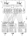
- FIGURE 1 there is shown a block diagram of an exemplary communication system 100 within which there are multiple user networks 102a, 102b...102n each of which utilize one more access systems 104a, 104b...104n to connect to a remote communications network 106.
- Each user network 102a, 102b... 102n is shown to be a single device, e.g. a user terminal like a mobile phone or a computer, with access capability provided by one reconfigurable access system or multiple access systems 104a, 104b...104n.
- the user networks 102a, 102b...102n can be an interconnection of multiple nodes, like for example a personal area network or a moving network within a vehicle, where the access capabilities are provided by the different nodes.
- the access systems 104a, 104b...104n can be either a wireless access system such as GSM, UMTS, UTRAN, E-UTRAN, GERAN, HSPA, LTE, WiMAX, WLAN, Bluetooth, etc... and/or a fixed access system such as Ethernet, CableModem, xDSL, fiber, etc....
- the availability and capabilities of the individual access systems 104a, 104b...104n can vary over time, e.g. due to movement of the user network 102a, 102b...102n, changes in the load of the access systems 104a, 104b...104n, etc.
- each user network 102a, 102b...102n has many different types of possible access connections 108 which can exist with multiple access systems 110a, 110b...110n that are associated with the remote communication network 106 (or multiple remote communications networks 106 where some access connections 108 belong to one remote communication network 106 and other access connections 108 belong to other remote communication networks 106).
- Each user network 102a, 102b...102n needs to be able to select one or more of these possible access connections 108 to establish one or more communication sessions with the remote communications network 106 (or multiple remote communications networks 106).
- each user network 102a, 102b...102n has a processor 112 that uses a MRRM entity 114 and a GLL entity 116 (or multiple GLL entities which correspond with the multiple access systems) to perform this access selection and to help establish the communication session(s) with the remote communications network 106 (or multiple remote communications networks 106).
- a processor 112 that uses a MRRM entity 114 and a GLL entity 116 (or multiple GLL entities which correspond with the multiple access systems) to perform this access selection and to help establish the communication session(s) with the remote communications network 106 (or multiple remote communications networks 106).
- each MRRM entity 114 maintains a number of different access sets (which are stored in memory 118) that have been classified as follows:
- Each user network 102a, 102b...102n has one DS and one VS, but they can be multiple CSs and ASs (indicated by CS i and AS i when appropriate) because a single CS and a single AS exists for every data bearer, which can transport either user or control data.
- CS i and AS may exist for a speech transmission which requires a low bandwidth
- AS may be exist for a video stream which requires a high bandwidth.
- a DS contains "possible access connections" (or access resources)
- the AS contains “access connections”
- the VS/CS can contain either one or the other (the difference between access resources and access connections is discussed in detail below with respect to FIGURES 6-8 ).
- the exemplary remote communications network 106 shown includes two separate nodes 118a and 118b each of which has a base station/radio access controller 120a and 120b.
- the exemplary remote communications network 106 includes a single MRRM entity 124 and two GLL entities 126a and 126b. If desired, the MRRM entity 124 could be co-located within one of the access systems 110a, 110b... 110n.
- Each access system 110a, 110b...110n is shown to have a RRM 111a, 111b...111n the function of which is to manage access resources as will be discussed later in this document.
- the MRRM entity 124 could be located in a core network such as for example an evolved packet core that is standardized in 3GPP mobile packet telecommunications networks. Plus, the GLL entities 126a and 126b could each be divided into multiple GLL entities with one GLL entity for each access system 110a, 110b...110n.
- Each user network 102a, 102b... 102n and in particular their respective MRRM entity 114 and GLL entity 116 function to determine and maintain the possible access connection(s) 108 which can be used to establish the communication session (s) with the remote communications network 106 (or multiple remote communications networks 106).
- each GLL entity 116 functions to monitor and observe the availability, capabilities and characteristics of each possible access connections 108 with the remote communications network 106 (or multiple remote communications networks 106). Then, the corresponding MRRM entity 114 uses this information to determine/validate which of the possible access connections 108 are to be admitted into the DS (in this example it is assumed that all of the possible access connections 108 are added to the DS).
- the MRRM entity 114 uses policy functions (e.g., security functions, compensation functions, local policies, remote policies) to determine which of the possible access connections 108 within the DS are to be admitted into the VS.
- policy functions e.g., security functions, compensation functions, local policies, remote policies
- the MRRM entity 114 upon receiving a bearer request determines which of the possible access connections 108 within the VS are to be admitted into the CS.
- the MRRM entity 114 determines which of the possible access connections 108 within the CS are to be placed in the AS and used as data bearer (s) for the communication session(s) with the remote communications network 106.
- FIGURE 2 there is illustrated a diagram which is used to help explain how one user network 102a (for example) and in particular their MRRM entity 114 and GLL entity 116 is able to determine and maintain the possible access connection (s) 108 which can be used to establish the communication session (s) with the remote communications network 106 (or multiple remote communications networks 106).
- the GLL entity 116 functions to monitor and observe the availability, capabilities and characteristics of each of the possible access connections 108 with the remote communications network 106 (or multiple remote communications networks 106).
- the GLL entity 116 can conduct quality measurements on the possible access connections 108 by measuring the field strength of a beacon signal and/or by measuring the possible bandwidth/access load based on broadcast information.
- the GLL entity 116 reports this information to the MRRM entity 114 (see dashed lines indicated by numerals 202a, 202b and 202c). Further, this information does not need to be retrieved from the broadcast information but instead it could be obtained from dedicated messages (e.g., after network attachment (discussed below) or via an already attached access). Alternatively, the MRRM entity 114 can obtain information/parameters which are signaled from other entities, like e.g., the MRRM entity 124 within the remote network 106.
- the MRRM entity 114 has an access detection function 204 which uses access discovery/monitoring information 202a (received from the GLL entity 116) to determine which of the possible access connections 108 are to be admitted into the DS (in this example it is assumed that all of the possible access connections 108 are added to the DS) .
- the MRRM entity 114 also has a first access control function 206 that determines which of the possible access connections 108 in the DS are to be added to the VS.
- the MRRM entity 114 implements the first access control function 206 which interacts with a policy function 208 (associated with processor 112) to obtain policy constraints 209a (e.g., security functions, compensation functions, local policies) and then uses this policy information 209a to determine/validate which of the possible access connections 508 from the DS are to be admitted within the VS.
- policy constraints 209a e.g., security functions, compensation functions, local policies
- the MRRM entity 114 has a second access control function 210 which upon receiving a data bearer request 212 which defines the service requirements from a bearer management function 214 (associated with processor 112) functions to interact with the policy function 208 to obtain policy constraints 209b and then uses this information along with the access performance/characteristics information 202b (received from the GLL entity 116) to determine which of the possible access connections 108 within the VS are to be admitted into the CS.
- the MRRM entity 114 implements the second access control function 210 and determines which of the possible access connections 108 within the VS could be placed within the CS and then possibly used as communication bearer(s) with the remote communications network 106.
- this procedure can be triggered by other events besides receiving the data bearer request 212 like, for instance, this procedure could be triggered when the GLL 116 detects a new AR 108 or when there is a change in the performance/characteristics of the monitored ARs 108.
- This process is performed for each communications session (e.g., data session) which means that there can be multiple CSs.
- the access connections 108 which are placed within anyone of the CSs depends on the requirements of the particular data bearer (e.g., the quality of service, required security, acceptable amount of costs etc%) and to what extent these requirements can be satisified by the access systems 104a, 104b...104n.
- the policy constraints 209b can dictate or restrict which of the access connections 108 can be admitted to the CSs.
- the MRRM entity 114 has an access selection function 216 which interacts with the policy function 208 to obtain policy constraints 209c and then uses this information along with the access performance/characteristics information 202c (received from the GLL entity 116) to determine which of the possible access connections 108 within the CS are to be used as data bearer(s) for the communication session(s) with the remote communications network 106 (note: anyone of the policy constraints 209a, 209b and 209c could alternatively be e.g., pushed or transmitted from any one of the access networks 110a, 110b...110n).
- the MRRM entity 114 implements the access selection function 216 to determine which one of the possible access connections 108 in the CS is to be placed in the AS and actually used as a communication bearer in a communication session that is established with the remote communications network 106.
- the access connection 108 which is best suited to be used for a particular communication session e.g., data bearer
- this AS selection can be seen as an optimization with respect to a certain cost or utility function.
- an AR is a resource which could be used for establishing connectivity and transmitting data (note: the RRMs 111a, 111b...111n manage the ARs).
- Examples of an AR include frequency bands/sub carriers, time slots, CDMA codes, transmit power, interference headroom and connection identifiers.
- An AR can be identified by an AR identity which can be composed of the id of the resource owner such as the network id and a resource specific id such as a cell id in a wireless access system. For instance, the AR identity could be ⁇ network id; access type; resource id ⁇ .
- the AR can be further characterized by AR-related information/AR-descriptor, such as total/occupied/available resources, resource costs, efficiency of the resource usage like a signal-to-noise-and-interference ratio.
- AR-related information/AR-descriptor such as total/occupied/available resources, resource costs, efficiency of the resource usage like a signal-to-noise-and-interference ratio.
- the AR corresponds to the underlying physical resources which are associated with the specific access system, e.g. for a UMTS cell it may correspond to available power, a certain number of codes, etc...
- the other connectivity element in the access systems 104a, 104b...104n is the logical connection (LC) (also known as access flow (AF)).
- the access system 104a, 104b...104n establishes the LC with the other access system 110a, 110b...110n based on the corresponding access resource.
- identifiers sometimes called locators
- the setup of the LC can include: (1) reserving radio resources for the LC; (2) performing AAA procedures; (3) establishing LC security associations; and (4) negotiating LC usage policies.
- the AR provides the capability to establish the connectivity and the LC is the data bearer on which data could be transmitted.
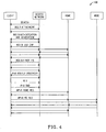
- FIGURES 3-5 illustrate three exemplary signal flow diagrams 300, 400 and 500 which are provided to indicate that there is a lot of signaling associated with establishing a network attachment.
- the signal flow diagram 300 shows an example of an attachment of a device to a cellular access system (e.g., the 3GPP LTE system described in 3GPP TR 23.882 V.1.2.3 (June 2006)).
- the signal flow diagram 400 shows an example of an attachment of a device to a WLAN network (the signaling shown includes link attachment, authentication, authorization, establishment of a security association for encryption and integrity protection, and IP address assignment).
- the signal flow diagram 500 shows an improved network attachment procedure which was developed by the AN project to help enable seamless connections between systems like the ones shown in FIGURES 3 and 4 .
- These signal flow diagrams 300, 400 and 500 are well known to those skilled in the art and have only been provided herein to indicate that it takes a lot of time and resources to change an AR into a LC.
- FIGURE 6 shows a user network 102a (for example) that currently has a DS, VS and CS that contain ARs and an AS that contains a LC.
- FIGURE 7 there is a user network 102b (for example) shown which has a DS and VS that contains ARs and a CS and AS that contains LCs.
- FIGURE 8 shows a user network 102n (for example) that currently has a DS which contains ARs, a VS and CS that contains ARs and LCs, and an AS which contains a LC.
- the pros and cons of these different scenarios are described in the aforementioned PCT Patent Application No. PCT/EP2006/068529 (note: the VS was not discussed in this document however many of the pros and cons of the different scenarios are still relevant).
- the user networks 102a, 102b...102n can all monitor the same AR and have it included in their VS and CS which means that this particular AR can be considered and evaluated for access selection by multiple user networks 102a, 102b...102n.
- This situation can be problematic because a large number of these user networks 102a, 102b...102n may try to access the AR in a short time period which may lead to an overload of the AR, a failure of the connection establishment, or a failure of the access selection procedure.
- this problem there is a need to address this problem and this need and other needs are satisfied by the present invention.
- the present invention provides a multi-resource management entity which implements a method comprising the steps of: (a) obtaining information about a potentially required access resource of one access network; (b) determining that more than a certain number of a user networks may potentially use the access resource to establish a connection with the one access network; (c) obtaining information indicating an availability of the access resource; and (d) limiting a number of the user networks that may potentially access the access resource in view of the obtained availability information.
- the limiting of the number of user networks that may potentially access the access resource is a marked-improvement over the state of art where a large number of the user networks could try to access the same access resource in a short time period which may lead to an overload of the access resource, a failure of the connection establishment, or a failure of the access selection procedure.
- the present invention provides an access resource managing entity which implements a method comprising the steps of: (a) obtaining information from a multi-resource managing entity where the information is related to a potentially required access resource that may be used by one or more user networks; (b) checking the availability of the potentially required access resource; (c) sending a report containing availability information back to the multi-resource managing entity.
- the multi-resource managing entity upon receiving the report is now able to limit the number of the user networks that may potentially access the access resource.
- the limiting of the number of user networks that may potentially access the access resource is a marked-improvement over the state of art where a large number of the user networks could try to access the same access resource in a short time period which may lead to an overload of the access resource, a failure of the connection establishment, or a failure of the access selection procedure.
- FIGURE 9 there is shown a block diagram of an exemplary communication system 900 within which there are multiple user networks 902a, 902b...902n each of which utilize one more access systems 904a, 904b...904n to connect to one or more remote communication networks 906 in accordance with the present invention.
- the communication system 900 has basically the same components and basically the same functionality as the communication system 100 except that the remote communication network 906 and in particular the MRM entity 924 and ARMs 911a, 911b...911n located therein implement a method 1000 to solve the aforementioned problem where too many user networks 902a, 902b...902n can monitor and try to access the same AR a short time period which could lead to an overload of the AR, a failure of the connection establishment, or a failure of the access selection procedure (note: the ARMs 911a, 911b... 911n could also be referred to as RRMs and the MRM entities 914 and 924 could also be referred to as MRRM entities 914 and 924 since this is a wireless access example).
- the MRM entity 924 upon implementing method 1000 would keep a list of ARs which are used in the VSs and/or CSs of different user networks 902a, 902b...902n. If a specific AR is in more than a certain number of VSs/CSs in the user networks 902a, 902b...902n, then the MRM entity 924 interacts with the corresponding ARM 911b (for example) which manages that particular AR to ask if sufficient resources of the AR are available to be used by this many user networks 902a, 902b...902n. If no, then the MRM entity 924 limits the number of user networks 902a, 902b...902n that may include that particular AR in their VSs/CSs. A detailed description is provided next about several different exemplary embodiments of method 1000.
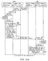
- FIGURE 10A there is a signal flow diagram which is used to help explain the steps of a method 1000a for optimizing access in a multi-access network environment in accordance with a first embodiment of the present invention.
- the signal flow diagram has the following steps:
- Steps 12-18 are associated with method 1000a while steps 1-11 and 19-24 are existing technology.
- the ARM 911b can notify the MRM entity 924 about a change of this situation. Then, the MRM entity 924 for example could limit the amount of time the AR can be allowed in the VS/CS of the user networks 902a, 902b...902n.
- MRM entity 924 there are different options of realizing the MRM entity 924. For instance, there can be one centralized MRM entity 924 in the remote communications network 906. Or, the MRM functionality can be distributed in multiple MRM entities 924. Alternatively, the MRM entity 924 could be co-located/embedded with the ARMs 911a, 911b...911n.
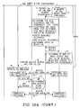
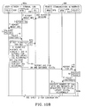
- FIGURE 10B there is a signal flow diagram which is used to help explain the steps of a method 1000b for optimizing access in a multi-access network environment in accordance with a second embodiment of the present invention.
- the signal flow diagram has the following steps:
- Steps 12-18 are associated with method 1000b while steps 1-11 and 19-24 are existing technology.
- the ARM 911b can notify the MRM entity 924 about a change of this situation. Then, the MRM entity 924 for example could limit the amount of time the AR can be allowed in the VS/CS of the user networks 902a, 902b...902n.
- MRM entity 924 there are different options of realizing the MRM entity 924. For instance, there can be one centralized MRM entity 924 in the remote communications network 906. Or, the MRM functionality can be distributed in multiple MRM entities 924. Alternatively, the MRM entity 924 can be co-located/embedded with the ARMs 911a, 911b...911n.
- the two methods 1000a and 1000b indicate that the ARM 911a (for example) knows about the usage of resources (load, availability) while the MRM entity 924 knows about what candidate ARs in the CS/VS are being considered as access connections by the user networks 902a, 902b...902n. Then, in method 1000a the MRM entity 924 reports to the ARM 911b the number of user networks 902a, 902b....902n that consider a particular AR as a candidate for an access connection. Thereafter, the ARM 911b determines depending on their resource knowledge if and to what extent this situation is feasible, and then sends a report back to the MRM entity 924.
- the ARM 911b has the major logic for determining whether to block or admit this AR in the CSs/VSs of the user networks 902a, 902b....902n. While, in method 1000b the MRM entity 924 sends a resource request to the ARM 911b and then receives "resource information" in the form of a report from the ARM 911b and then determines if and how many user networks 902a, 902b...902n should have the same AR in their CSs/VSs. In this scheme, the MRM entity 924 has the major logic for determining whether to block or admit this AR in the CSs/VSs of the user networks 902a, 902b....902n.
- the ARM 911b (in method 1000a) or the MRM entity 924 (in method 1000b) needs to estimate the required resources based on the number of user networks 902a, 902b...902n that are considering to use the same AR as a candidate for access connections.
- Exemplary ways/logic about how the ARM 911b (and other ARMS 911a...911n) or the MRM entity 924 can estimate the required resources are as follows:
- FIGURES 11A-11C there are several diagrams of an exemplary MRRM 924 and an exemplary ARM 911b which are used to help explain another method for optimizing access in a multi-access network environment in accordance with a third embodiment of the present invention.
- the steps are as follows:
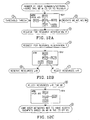
- FIGURES 12A-12C there are several diagrams of an exemplary MRRM 924' and an exemplary ARM 911b' which are used to help explain one way that different components can be incorporated therein to implement the method discussed with respect to FIGURES 11A-11C .
- FIGURE 12A depicts an exemplary MRM entity 924' (which corresponds with the MRM entity 924 shown in FIGURE 11A ) that determines R and sends a resource reservation request R by using at least one receiving unit RU11 (which receives the aforementioned N, n, M and m values), at least one receiving unit RU12 (which receives the weights w 1 -w 4 ), at least one receiving unit RU13 (which receives Thresh), at least one processing unit PU11 (which processes all of the received values), at least one transmission unit TU11 (which transmits the resource reservation request R) , and preferably at least one storage unit SU11 (which stores various values and program instructions).
- the units may be combined, e.g. multiple receiving units RU11-RU13 and transmitting unit TU11 may be implemented within a single transmitter. Plus, the Thresh and/or the weights w 1 -w 4 may alternatively be obtained from the storage SU11.
- FIGURE 12B depicts an exemplary ARM 911b' (which corresponds with the ARM 911b shown in FIGURE 11B ) that receives the resource reservation request R and outputs the amount of resources that are reserved (reserve resources ⁇ *R) and the amount of resources that are rejected (reject resources v*R).
- the exemplary ARM 911b' does this by using at least one receiving unit RU21 (which receives the resource reservation request R), at least one processing unit PU21 (which processes the resource reservation request R), at least one transmission unit TU21 (which transmits the reserve resources ⁇ *R), at least one transmission unit T22 (which transmits the reject resources v*R) and preferably at least one storage unit SU21.
- the units may be combined, e.g. the receiving unit RU21 and multiple transmitting units TU21 and TU22 may be implemented within a single transmitter.
- FIGURE 12C depicts an exemplary MRM entity 924' (which corresponds with the MRM entity 924 shown in FIGURE 11C ) that receives the reject resources v*R and outputs information associated with limiting the usage of the AR in the VS and/or CS of the user networks 902a, 902b...902n.
- the exemplary MRM entity 924' does this by using at least one receiving unit RU31 (which receives the reject resources v*R), at least one processing unit PU31, at least one transmission unit TU31 (which outputs information associated with limiting the usage of the AR in user networks 902a, 902b...902n), and preferably at least one storage unit SU31.
- the units may be combined, e.g. the receiving unit RU31 and transmitting unit TU31 may be implemented within a single transmitter.
- the present invention also concerns computer programs that include portions of software codes that can be retrieved to enable the implementation of anyone of the methods 1000 described herein when operated at a multi-resource managing entity like e.g. a MRM and an access resource managing entity like e.g. an ARM.
- the respective computer programs can be stored on one or more computer readable media.
- the computer readable media can be a permanent or rewritable memory within the MRM entity 924, the ARM 911a, 911b...911n, or located externally.
- the respective computer programs can be also transferred to the MRM entity 924 and the ARM 911a, 911b...911n for example via a cable or a wireless link as a sequence of signals.
- MRRM refers to a multi-radio resource management entity. This term is used on a common basis in the context of an wireless access environment. However, the present invention can also be used in a fixed access environment and not just in a wireless access environment. Therefore, although the term MRRM is used in some the examples provided in the aforementioned description, the term MRM alias Multi-Resource Management could have also been used to reflect that the present invention applies to wireless and/or fixed access environment. Thus, for pure wireless embodiments the term MRRM is strictly correct and may be applied unchanged. But, for fixed access embodiments with or without wireless access, the term MRM may be used.
- the examples provided herein could be easily adapted to such fixed and/or wireless network access environments by replacing the MRRM by MRM.
- the term ARM is an example for an access resource managing entity which may manage wireless and/or fixed access resources.
- the term RRM can be used to describe an access resource managing entity which manages only wireless access resources.
- the present invention relates to a MRM entity 924 (or MRRM 924) that keeps a list of ARs which are used in the VSs and/or CSs of different user networks 902a, 902b...902n. If a specific AR is in more than a certain number of VSs/CSs in the user networks 902a, 902b...902n, then the MRM entity 924 interacts with the corresponding ARM 911b (for example) which manages that particular AR to ask if sufficient resources of the AR are available to be used by this many user networks 902a, 902b...902n. If no, then the MRM entity 924 limits the number of user networks 902a, 902b...
- the present invention solves the aforementioned problem where too many user networks 902a, 902b... 902n could monitor and try to access the same AR in a short time period which could lead to an overload of the AR, a failure of the connection establishment, or a failure of the access selection procedure. Plus, the present invention has many other advantages some of which are as follows:
- the present invention in addition to the aforementioned multi-access network is applicable to different types of multi-access network environments wherein for instance an access resource managing entity may be embodied in a network intrinsic RRM and the MRRM may communicate with the network intrinsic RRM via the GLL.
- the network intrinsic RRM (as examples for access resource managing entities) may reside at an RNC or a WLAN access point.
- an intrinsic RRM is an access-specific RRM which is also often used in an AN.
Landscapes
- Engineering & Computer Science (AREA)
- Computer Networks & Wireless Communication (AREA)
- Signal Processing (AREA)
- Quality & Reliability (AREA)
- Mobile Radio Communication Systems (AREA)
- Data Exchanges In Wide-Area Networks (AREA)
Claims (20)
- Procédé pour optimiser l'accès dans un environnement de réseau à accès multiples, dans lequel une entité de gestion de ressources multiples (924,924') pour gérer l'accès à au moins un réseau d'accès (904a, 904...904n) effectue les étapes suivantes consistant à :obtenir une information concernant une ressource d'accès potentiellement requise d'un de au moins un réseau d'accès (904a, 904...904n) ;déterminer que plus d'un certain nombre de réseaux d'utilisateur (902a,902b...902n) peuvent potentiellement utiliser la ressource d'accès afin d'établir une connexion avec un réseau d'accès ;obtenir une information indiquant une disponibilité de la ressource d'accès ; etlimiter un nombre de réseaux d'utilisateur (902a,902b...902n) qui peuvent potentiellement accéder à la ressource d'accès en vue de l'information de disponibilité obtenue.
- Procédé selon la revendication 1, dans lequel ladite information concernant la ressource d'accès potentiellement requise comprend une information de ce que la ressource d'accès et/ou un flux d'accès afférent fait partie d'un ensemble validé ou d'un ensemble candidat dans chacun des réseaux d'utilisateur (902a, 902b...902n) .
- rocédé selon la revendication 1 ou 2, dans lequel ladite étape d'obtention d'une information indiquant la disponibilité de la ressource d'accès comprend en outre de :envoyer un message indiquant un nombre des réseaux d'utilisateur (902a,902b...902n) qui peuvent potentiellement utiliser la ressource d'accès à une entité de gestion de ressource d' a c c è s (911a, 911b...911n, 911b') qui est aussi associée à un réseau d'accès, dans lequel l'entité de gestion de ressource d'accès (911a, 911b...911n, 911b' détermine combien de ressources doivent être réservées en calculant une quantité requise de ressources qui sont escomptées être utilisées par les réseaux d'utilisateur (902a,902b..902n), vérifie la disponibilité de la ressource d'accès, pré-réserve les ressources associées à la ressource d'accès, et renvoie un rapport contenant une information de disponibilité concernant les ressources pré-réservées à l'entité de gestion de ressources multiplex (924, 924').
- Procédé selon la revendication 1 ou 2, dans lequel ladite étape d'obtention d'une information indiquant la disponibilité de la ressource d'accès comprend en outre de :déterminer combien de ressources doivent être réservées en calculant une quantité requise de ressources qui sont escomptées être utilisées par les réseaux d'utilisateur (902a,902b...902n) ; et envoyer un message de demande de réservation indiquant au moins la quantité requise de ressources à une entité de gestion de ressources d'accès (911a, 911b...911n, 911b') qui est aussi associée à un réseau d'accès, dans lequel l'entité de gestion de ressource d'accès (911a,911b...911n,911b') vérifie la disponibilité de la ressource d'accès, pré-réserve les ressources associées à la ressource d'accès, et renvoie un rapport contenant une information de disponibilité concernant les ressources pré-réservées à l'entité de gestion de ressources multiples (924,924').
- Procédé selon la revendication 3 ou 4, dans lequel la quantité requise de ressources calculée est au moins basée sur une probabilité que ces ressources sont escomptées être utilisées par les réseaux d'utilisateur (902a, 902b...902n) .
- Procédé selon la revendication 3 ou 4, dans lequel la quantité requise de ressources calculée est au moins basée sur au moins une d'une mesure antérieure, une valeur prédéterminée, une exigence de support estimée ou des valeurs pondérées.
- Procédé selon la revendication 3 ou 4, dans lequel ledit rapport contient en outre une information de disponibilité concernant une fraction des réseaux d'utilisateur (902a,902b...902n) qui doivent être rejetés.
- Procédé selon la revendication 3 ou 4, dans lequel ladite entité de gestion de ressources d'accès (911a, 911b...911n, 911b') est réalisée en une entité de gestion de ressources radio intrinsèque au réseau.
- Produit de programme informatique comprenant du code logiciel chargeable dans une unité de traitement (PU11,PU31) d'une entité de gestion de ressources multiples (924,924') adaptée afin d'exécuter toutes les étapes d'un procédé selon une quelconque des revendications 1 à 6.
- Entité de gestion de ressources multiples (924,924') comprenant :une unité de traitement (PU11,PU31) ; etune unité de mémorisation (SU11,SU31), où ladite unité de traitement (PU11,PU31) obtient des instructions de ladite unité de mémorisation (SU11,SU31) et traite ces instructions afin de permettre ce qui suit :obtenir une information concernant une ressource d'accès potentiellement requise d'un de au moins un réseau d'accès (904a, 904...904n) ;déterminer que plus d'un certain nombre de réseaux d'utilisateur (902a,902b...902n) peuvent potentiellement utiliser la ressource d'accès afin d'établir une connexion avec un réseau d'accès ;obtenir une information indiquant une disponibilité de la ressource d'accès ; etlimiter un nombre de réseaux d'utilisateur (902a,902b...902n) qui peuvent potentiellement accéder à la ressource d'accès en vue de l'information de disponibilité obtenue.
- Entité de gestion de ressources multiples (924,924') selon la revendication 10, dans laquelle ladite information concernant la ressource d'accès potentiellement requise inclut une information de ce que la ressource d'accès et/ou un flux d'accès afférent fait partie d'un ensemble validé ou d'un ensemble candidat dans chacun des réseaux d'utilisateur (902a, 902b...902n) .
- Entité de gestion de ressources multiples (924,924') selon la revendication 10, dans lequel ladite unité de traitement (PU11,PU31) est adaptée afin d'exécuter les étapes du procédé selon une quelconque des revendications 3 à 7.
- Procédé pour optimiser l'accès dans un environnement de réseau à accès multiples, dans lequel une entité de gestion de ressources d'accès (911a, 911b...911n, 911b') gérant l'accès à au moins une ressource d'accès exécute les étapes suivantes :obtenir une information provenant d'une entité de gestion de ressources multiples (924,924') où ladite information est afférente à une ressource d'accès potentiellement requise qui peut être utilisée par un ou plusieurs réseaux d'utilisateur (902a,902b...902n) ;vérifier la disponibilité de la ressource d'accès potentiellement requise ; etrenvoyer un rapport contenant une information de disponibilité à l'entité de gestion de ressources multiples (924, 924').
- Procédé selon la revendication 13, comprenant en outre l'étape de pré-réservation des ressources associées à la ressource d'accès potentiellement requise, l'information de disponibilité comprenant une information concernant les ressources pré-réservées et une information concernant la fraction des réseaux d'utilisateur (902a,902b...902n) qui doivent être rejetés.
- Procédé selon la revendication 13, dans lequel ladite information obtenue inclut une demande de réservation indiquant au moins une quantité requise de la ressource d'accès.
- Procédé selon la revendication 13, dans lequel si ladite information obtenue inclut une indication d'un nombre de réseaux d'utilisateur (902a,902b...902n) qui peuvent éventuellement utiliser la ressource d'accès, alors ladite entité de gestion de ressource d'accès (911a,911b...911n,911b') avant d'exécuter l'étape de vérification et l'étape d'envoi exécute une étape pour déterminer combien de ressources sont escomptées être utilisées par les réseaux d'utilisateur (902a, 902b...902n) .
- Produit de programme informatique comprenant du code logiciel chargeable dans une unité de traitement (PU21) d'une entité de gestion de ressources d'accès (911a, 911b...911n, 911b) adaptée afin d'exécuter toutes les étapes d'un procédé selon une quelconque des revendications 13 à 16.
- Entité de gestion de ressource d'accès (911a, 911b ... 911n, 911b") comprenant:une unité de traitement (PU21) ; etune unité de mémorisation (SU21), où ladite unité de traitement (PU21) obtient des instructions de ladite unité de mémorisation (SU21) et traite ces instructions pour permettre ce qui suit :obtenir une information d'une entité de gestion de ressources multiples (924,924') où ladite information est relative à une ressource d'accès potentiellement requise qui peut être utilisée par un ou plusieurs réseaux (902a, 902b...902n) ;vérifier la disponibilité de la ressource d'accès potentiellement requise ; etrenvoyer un rapport contenant une information de disponibilité à l'entité de gestion de ressources multiples (924, 924').
- Entité de gestion de ressources d'accès (911a,911b...911n,911b') selon la revendication 18, dans lequel ladite unité de traitement (PU21) permet en outre une pré-réservation de ressources associées à la ressource d'accès potentiellement requise avec l'information de disponibilité comprenant l'information concernant les ressources pré-réservées et une information concernant la fraction des réseaux d'utilisateur (902a,902b...902n) qui doivent être rejetés.
- Entité de gestion de ressources d'accès (911a,911b...911n,911b') selon la revendication 18, dans lequel ladite unité de traitement (PU21) avant de permettre l'opération de vérification et l'opération d'envoi permet une détermination de combien de ressources sont escomptées être utilisées par les réseaux d'utilisateur (902a, 902b...902n).
Priority Applications (1)
| Application Number | Priority Date | Filing Date | Title |
|---|---|---|---|
| EP07847166A EP2092696B1 (fr) | 2006-11-15 | 2007-11-14 | Réservation et admission de ressources d'accès pour une sélection d'accès dans des réseaux à multiples accès |
Applications Claiming Priority (3)
| Application Number | Priority Date | Filing Date | Title |
|---|---|---|---|
| EP2006068529 | 2006-11-15 | ||
| PCT/EP2007/062342 WO2008058998A1 (fr) | 2006-11-15 | 2007-11-14 | Réservation et admission de ressources d'accès pour une sélection d'accès dans des réseaux à multiples accès |
| EP07847166A EP2092696B1 (fr) | 2006-11-15 | 2007-11-14 | Réservation et admission de ressources d'accès pour une sélection d'accès dans des réseaux à multiples accès |
Publications (2)
| Publication Number | Publication Date |
|---|---|
| EP2092696A1 EP2092696A1 (fr) | 2009-08-26 |
| EP2092696B1 true EP2092696B1 (fr) | 2010-09-15 |
Family
ID=39171351
Family Applications (1)
| Application Number | Title | Priority Date | Filing Date |
|---|---|---|---|
| EP07847166A Not-in-force EP2092696B1 (fr) | 2006-11-15 | 2007-11-14 | Réservation et admission de ressources d'accès pour une sélection d'accès dans des réseaux à multiples accès |
Country Status (6)
| Country | Link |
|---|---|
| US (1) | US20100250688A1 (fr) |
| EP (1) | EP2092696B1 (fr) |
| CN (1) | CN101622829B (fr) |
| AT (1) | ATE481802T1 (fr) |
| DE (1) | DE602007009296D1 (fr) |
| WO (1) | WO2008058998A1 (fr) |
Families Citing this family (16)
| Publication number | Priority date | Publication date | Assignee | Title |
|---|---|---|---|---|
| EP2288091A1 (fr) * | 2009-08-13 | 2011-02-23 | Institut Eurecom G.I.E. | Procédé pour contrôler le rattachement d'un terminal mobile à un point d'attachement particulier qui appartient à une technologie d'accès sans fil au réseau |
| CN101801033B (zh) * | 2010-01-29 | 2012-11-28 | 杭州华三通信技术有限公司 | 一种ac选择方法和设备 |
| WO2011114471A1 (fr) * | 2010-03-17 | 2011-09-22 | 富士通株式会社 | Station mobile, station de base, système de communication et procédé de communication |
| CN102098685B (zh) * | 2011-03-25 | 2013-06-26 | 西安电子科技大学 | 基于gsm网络的频谱重用通信系统及方法 |
| US9529629B2 (en) * | 2012-12-20 | 2016-12-27 | Bank Of America Corporation | Computing resource inventory system |
| US9189644B2 (en) | 2012-12-20 | 2015-11-17 | Bank Of America Corporation | Access requests at IAM system implementing IAM data model |
| US9489390B2 (en) | 2012-12-20 | 2016-11-08 | Bank Of America Corporation | Reconciling access rights at IAM system implementing IAM data model |
| US9483488B2 (en) | 2012-12-20 | 2016-11-01 | Bank Of America Corporation | Verifying separation-of-duties at IAM system implementing IAM data model |
| US9537892B2 (en) | 2012-12-20 | 2017-01-03 | Bank Of America Corporation | Facilitating separation-of-duties when provisioning access rights in a computing system |
| US9477838B2 (en) | 2012-12-20 | 2016-10-25 | Bank Of America Corporation | Reconciliation of access rights in a computing system |
| US9639594B2 (en) | 2012-12-20 | 2017-05-02 | Bank Of America Corporation | Common data model for identity access management data |
| US9495380B2 (en) | 2012-12-20 | 2016-11-15 | Bank Of America Corporation | Access reviews at IAM system implementing IAM data model |
| US9542433B2 (en) | 2012-12-20 | 2017-01-10 | Bank Of America Corporation | Quality assurance checks of access rights in a computing system |
| CN109167655B (zh) | 2013-01-18 | 2019-09-20 | 华为技术有限公司 | 公共控制信道的检测方法、传输方法及装置 |
| US9655147B2 (en) | 2013-12-18 | 2017-05-16 | Motorola Solutions, Inc. | Method and apparatus for bearer control in a group call |
| CN106061572A (zh) * | 2014-01-24 | 2016-10-26 | 华为技术有限公司 | 信息传输的方法、用户设备及基站 |
Family Cites Families (13)
| Publication number | Priority date | Publication date | Assignee | Title |
|---|---|---|---|---|
| GB9928503D0 (en) * | 1999-12-03 | 2000-02-02 | Ibm | Resource allocation in data processing systems |
| US7194280B2 (en) * | 2000-01-12 | 2007-03-20 | Telefonaktiebolaget Lm Ericsson (Publ) | Mobile station assisted forward link open loop power and rate control in a CDMA system |
| US7230921B2 (en) * | 2001-04-02 | 2007-06-12 | Telefonaktiebolaget Lm Ericsson (Publ) | Concurrent use of communication paths in a multi-path access link to an IP network |
| US7353416B2 (en) * | 2001-07-25 | 2008-04-01 | Hewlett-Packard Development Company, L.P. | Wireless access point seek mode for wireless access clients |
| US20040103204A1 (en) * | 2002-11-27 | 2004-05-27 | Docomo Communications Laboratories Usa, Inc. | Method of connecting a client device with a router in a wireless communication network |
| US7873736B1 (en) * | 2003-03-21 | 2011-01-18 | Cisco Technology, Inc. | Replenishing a user account with more access resources needed for accessing network services |
| CN1887012B (zh) * | 2003-12-17 | 2010-12-08 | 艾利森电话股份有限公司 | 用于通信系统中的无线电资源管理的系统和方法 |
| WO2005089246A2 (fr) * | 2004-03-13 | 2005-09-29 | Cluster Resources, Inc. | Systeme et procede destines a effectuer des reservations avancees dans un environnement de calcul |
| KR101244082B1 (ko) * | 2004-09-06 | 2013-03-18 | 텔레폰악티에볼라겟엘엠에릭슨(펍) | 다양한 액세스 기술을 통한 다중 액세스 통신 |
| US8156500B2 (en) * | 2005-07-01 | 2012-04-10 | Microsoft Corporation | Real-time self tuning of planned actions in a distributed environment |
| DE102005042536A1 (de) * | 2005-09-07 | 2007-03-15 | Siemens Ag | Verfahren zum Betreiben einer Funk-Kommunikation in einem Multi-Funkverbindungs-Kommunikationsssystem |
| US8086723B2 (en) * | 2006-05-17 | 2011-12-27 | Alcatel Lucent | Apparatus and methods for managing communication system resources |
| US20080090520A1 (en) * | 2006-10-17 | 2008-04-17 | Camp William O | Apparatus and methods for communication mobility management using near-field communications |
-
2007
- 2007-11-14 AT AT07847166T patent/ATE481802T1/de not_active IP Right Cessation
- 2007-11-14 EP EP07847166A patent/EP2092696B1/fr not_active Not-in-force
- 2007-11-14 US US12/514,767 patent/US20100250688A1/en not_active Abandoned
- 2007-11-14 CN CN2007800424774A patent/CN101622829B/zh not_active Expired - Fee Related
- 2007-11-14 WO PCT/EP2007/062342 patent/WO2008058998A1/fr not_active Ceased
- 2007-11-14 DE DE602007009296T patent/DE602007009296D1/de active Active
Also Published As
| Publication number | Publication date |
|---|---|
| WO2008058998A1 (fr) | 2008-05-22 |
| US20100250688A1 (en) | 2010-09-30 |
| ATE481802T1 (de) | 2010-10-15 |
| DE602007009296D1 (de) | 2010-10-28 |
| CN101622829B (zh) | 2012-12-12 |
| CN101622829A (zh) | 2010-01-06 |
| EP2092696A1 (fr) | 2009-08-26 |
Similar Documents
| Publication | Publication Date | Title |
|---|---|---|
| EP2092696B1 (fr) | Réservation et admission de ressources d'accès pour une sélection d'accès dans des réseaux à multiples accès | |
| KR102469191B1 (ko) | 정보 전송방법 및 장치, 컴퓨터 판독가능 저장 매체 | |
| US8531967B2 (en) | Optimizing the usage of radio resources by cross-layer reading of information from higher level control plane protocol layer | |
| EP1858210A1 (fr) | Procédé et système pour un accès adaptative à un service de communication | |
| EP3834582B1 (fr) | Procédé et appareil pour commander une qualité de service de liaison latérale | |
| WO2020239195A1 (fr) | Nœuds de réseau pour une sélection conjointe d'hôte mec et d'upf | |
| US20220060942A1 (en) | Network Nodes for Handling Non-Fulfillment of QoS Requirements | |
| JP4422101B2 (ja) | 途切れずに引渡しを行うためのコンテキスト転送 | |
| CN101292552A (zh) | 多址接入通信网络中的方法和装置 | |
| EP2412186A1 (fr) | Système de gestion de réseau | |
| EP1540979B1 (fr) | Procede permettant de fournir des services de telecommunications, systeme associe et produit de technique d'informations | |
| CN113228776A (zh) | 用于不受管理的通信链接的资源分配 | |
| CN101262695A (zh) | 一种接入网进行无线资源管理的方法和装置 | |
| US12418473B2 (en) | Systems and methods for providing multipath connectivity intelligence | |
| US8917699B2 (en) | User network and method for using multiple access system to connect to remote communication network(s) | |
| EP4082180B1 (fr) | Système et procédé de gestion de quota de données mobiles | |
| CN120730474A (zh) | 针对切片之间的预期资源管理的支持 | |
| WO2025013092A1 (fr) | Procédé et système de gestion de cellules sous-performantes dans un réseau de communication | |
| WO2025119773A1 (fr) | Procédé pour mettre en œuvre des services de communication, notamment pour modifier le comportement du réseau et/ou pour en optimiser les performances | |
| CN120499768A (zh) | 通信调度的方法、装置及电子设备 | |
| CN118488088A (zh) | 数据服务能力的开放方法、装置和相关产品 | |
| CN118200398A (zh) | 服务选择方法、装置、选择端、网络功能及可读存储介质 | |
| WO2017128835A1 (fr) | Procédé et appareil pour optimiser un débit binaire de communication |
Legal Events
| Date | Code | Title | Description |
|---|---|---|---|
| PUAI | Public reference made under article 153(3) epc to a published international application that has entered the european phase |
Free format text: ORIGINAL CODE: 0009012 |
|
| 17P | Request for examination filed |
Effective date: 20090529 |
|
| AK | Designated contracting states |
Kind code of ref document: A1 Designated state(s): AT BE BG CH CY CZ DE DK EE ES FI FR GB GR HU IE IS IT LI LT LU LV MC MT NL PL PT RO SE SI SK TR |
|
| GRAP | Despatch of communication of intention to grant a patent |
Free format text: ORIGINAL CODE: EPIDOSNIGR1 |
|
| DAX | Request for extension of the european patent (deleted) | ||
| GRAS | Grant fee paid |
Free format text: ORIGINAL CODE: EPIDOSNIGR3 |
|
| GRAA | (expected) grant |
Free format text: ORIGINAL CODE: 0009210 |
|
| AK | Designated contracting states |
Kind code of ref document: B1 Designated state(s): AT BE BG CH CY CZ DE DK EE ES FI FR GB GR HU IE IS IT LI LT LU LV MC MT NL PL PT RO SE SI SK TR |
|
| REG | Reference to a national code |
Ref country code: CH Ref legal event code: EP Ref country code: GB Ref legal event code: FG4D |
|
| REG | Reference to a national code |
Ref country code: IE Ref legal event code: FG4D |
|
| REF | Corresponds to: |
Ref document number: 602007009296 Country of ref document: DE Date of ref document: 20101028 Kind code of ref document: P |
|
| REG | Reference to a national code |
Ref country code: NL Ref legal event code: VDEP Effective date: 20100915 |
|
| PG25 | Lapsed in a contracting state [announced via postgrant information from national office to epo] |
Ref country code: AT Free format text: LAPSE BECAUSE OF FAILURE TO SUBMIT A TRANSLATION OF THE DESCRIPTION OR TO PAY THE FEE WITHIN THE PRESCRIBED TIME-LIMIT Effective date: 20100915 Ref country code: FI Free format text: LAPSE BECAUSE OF FAILURE TO SUBMIT A TRANSLATION OF THE DESCRIPTION OR TO PAY THE FEE WITHIN THE PRESCRIBED TIME-LIMIT Effective date: 20100915 Ref country code: LT Free format text: LAPSE BECAUSE OF FAILURE TO SUBMIT A TRANSLATION OF THE DESCRIPTION OR TO PAY THE FEE WITHIN THE PRESCRIBED TIME-LIMIT Effective date: 20100915 |
|
| LTIE | Lt: invalidation of european patent or patent extension |
Effective date: 20100915 |
|
| PG25 | Lapsed in a contracting state [announced via postgrant information from national office to epo] |
Ref country code: SI Free format text: LAPSE BECAUSE OF FAILURE TO SUBMIT A TRANSLATION OF THE DESCRIPTION OR TO PAY THE FEE WITHIN THE PRESCRIBED TIME-LIMIT Effective date: 20100915 Ref country code: PL Free format text: LAPSE BECAUSE OF FAILURE TO SUBMIT A TRANSLATION OF THE DESCRIPTION OR TO PAY THE FEE WITHIN THE PRESCRIBED TIME-LIMIT Effective date: 20100915 Ref country code: CY Free format text: LAPSE BECAUSE OF FAILURE TO SUBMIT A TRANSLATION OF THE DESCRIPTION OR TO PAY THE FEE WITHIN THE PRESCRIBED TIME-LIMIT Effective date: 20100915 |
|
| PG25 | Lapsed in a contracting state [announced via postgrant information from national office to epo] |
Ref country code: GR Free format text: LAPSE BECAUSE OF FAILURE TO SUBMIT A TRANSLATION OF THE DESCRIPTION OR TO PAY THE FEE WITHIN THE PRESCRIBED TIME-LIMIT Effective date: 20101216 Ref country code: LV Free format text: LAPSE BECAUSE OF FAILURE TO SUBMIT A TRANSLATION OF THE DESCRIPTION OR TO PAY THE FEE WITHIN THE PRESCRIBED TIME-LIMIT Effective date: 20100915 Ref country code: SE Free format text: LAPSE BECAUSE OF FAILURE TO SUBMIT A TRANSLATION OF THE DESCRIPTION OR TO PAY THE FEE WITHIN THE PRESCRIBED TIME-LIMIT Effective date: 20100915 |
|
| PG25 | Lapsed in a contracting state [announced via postgrant information from national office to epo] |
Ref country code: CZ Free format text: LAPSE BECAUSE OF FAILURE TO SUBMIT A TRANSLATION OF THE DESCRIPTION OR TO PAY THE FEE WITHIN THE PRESCRIBED TIME-LIMIT Effective date: 20100915 Ref country code: PT Free format text: LAPSE BECAUSE OF FAILURE TO SUBMIT A TRANSLATION OF THE DESCRIPTION OR TO PAY THE FEE WITHIN THE PRESCRIBED TIME-LIMIT Effective date: 20110117 Ref country code: EE Free format text: LAPSE BECAUSE OF FAILURE TO SUBMIT A TRANSLATION OF THE DESCRIPTION OR TO PAY THE FEE WITHIN THE PRESCRIBED TIME-LIMIT Effective date: 20100915 Ref country code: SK Free format text: LAPSE BECAUSE OF FAILURE TO SUBMIT A TRANSLATION OF THE DESCRIPTION OR TO PAY THE FEE WITHIN THE PRESCRIBED TIME-LIMIT Effective date: 20100915 Ref country code: NL Free format text: LAPSE BECAUSE OF FAILURE TO SUBMIT A TRANSLATION OF THE DESCRIPTION OR TO PAY THE FEE WITHIN THE PRESCRIBED TIME-LIMIT Effective date: 20100915 Ref country code: IS Free format text: LAPSE BECAUSE OF FAILURE TO SUBMIT A TRANSLATION OF THE DESCRIPTION OR TO PAY THE FEE WITHIN THE PRESCRIBED TIME-LIMIT Effective date: 20110115 Ref country code: RO Free format text: LAPSE BECAUSE OF FAILURE TO SUBMIT A TRANSLATION OF THE DESCRIPTION OR TO PAY THE FEE WITHIN THE PRESCRIBED TIME-LIMIT Effective date: 20100915 |
|
| PG25 | Lapsed in a contracting state [announced via postgrant information from national office to epo] |
Ref country code: MC Free format text: LAPSE BECAUSE OF NON-PAYMENT OF DUE FEES Effective date: 20101130 Ref country code: BE Free format text: LAPSE BECAUSE OF FAILURE TO SUBMIT A TRANSLATION OF THE DESCRIPTION OR TO PAY THE FEE WITHIN THE PRESCRIBED TIME-LIMIT Effective date: 20100915 Ref country code: ES Free format text: LAPSE BECAUSE OF FAILURE TO SUBMIT A TRANSLATION OF THE DESCRIPTION OR TO PAY THE FEE WITHIN THE PRESCRIBED TIME-LIMIT Effective date: 20101226 |
|
| PLBE | No opposition filed within time limit |
Free format text: ORIGINAL CODE: 0009261 |
|
| STAA | Information on the status of an ep patent application or granted ep patent |
Free format text: STATUS: NO OPPOSITION FILED WITHIN TIME LIMIT |
|
| REG | Reference to a national code |
Ref country code: FR Ref legal event code: ST Effective date: 20110801 |
|
| 26N | No opposition filed |
Effective date: 20110616 |
|
| PG25 | Lapsed in a contracting state [announced via postgrant information from national office to epo] |
Ref country code: DK Free format text: LAPSE BECAUSE OF FAILURE TO SUBMIT A TRANSLATION OF THE DESCRIPTION OR TO PAY THE FEE WITHIN THE PRESCRIBED TIME-LIMIT Effective date: 20100915 |
|
| REG | Reference to a national code |
Ref country code: DE Ref legal event code: R097 Ref document number: 602007009296 Country of ref document: DE Effective date: 20110616 |
|
| PG25 | Lapsed in a contracting state [announced via postgrant information from national office to epo] |
Ref country code: FR Free format text: LAPSE BECAUSE OF NON-PAYMENT OF DUE FEES Effective date: 20101130 Ref country code: IE Free format text: LAPSE BECAUSE OF NON-PAYMENT OF DUE FEES Effective date: 20101114 |
|
| PG25 | Lapsed in a contracting state [announced via postgrant information from national office to epo] |
Ref country code: IT Free format text: LAPSE BECAUSE OF NON-PAYMENT OF DUE FEES Effective date: 20101114 Ref country code: MT Free format text: LAPSE BECAUSE OF FAILURE TO SUBMIT A TRANSLATION OF THE DESCRIPTION OR TO PAY THE FEE WITHIN THE PRESCRIBED TIME-LIMIT Effective date: 20100915 |
|
| REG | Reference to a national code |
Ref country code: CH Ref legal event code: PL |
|
| PG25 | Lapsed in a contracting state [announced via postgrant information from national office to epo] |
Ref country code: CH Free format text: LAPSE BECAUSE OF NON-PAYMENT OF DUE FEES Effective date: 20111130 Ref country code: LI Free format text: LAPSE BECAUSE OF NON-PAYMENT OF DUE FEES Effective date: 20111130 |
|
| PG25 | Lapsed in a contracting state [announced via postgrant information from national office to epo] |
Ref country code: BG Free format text: LAPSE BECAUSE OF FAILURE TO SUBMIT A TRANSLATION OF THE DESCRIPTION OR TO PAY THE FEE WITHIN THE PRESCRIBED TIME-LIMIT Effective date: 20100915 Ref country code: HU Free format text: LAPSE BECAUSE OF FAILURE TO SUBMIT A TRANSLATION OF THE DESCRIPTION OR TO PAY THE FEE WITHIN THE PRESCRIBED TIME-LIMIT Effective date: 20110316 Ref country code: LU Free format text: LAPSE BECAUSE OF NON-PAYMENT OF DUE FEES Effective date: 20101114 |
|
| PG25 | Lapsed in a contracting state [announced via postgrant information from national office to epo] |
Ref country code: TR Free format text: LAPSE BECAUSE OF FAILURE TO SUBMIT A TRANSLATION OF THE DESCRIPTION OR TO PAY THE FEE WITHIN THE PRESCRIBED TIME-LIMIT Effective date: 20100915 |
|
| PG25 | Lapsed in a contracting state [announced via postgrant information from national office to epo] |
Ref country code: BG Free format text: LAPSE BECAUSE OF FAILURE TO SUBMIT A TRANSLATION OF THE DESCRIPTION OR TO PAY THE FEE WITHIN THE PRESCRIBED TIME-LIMIT Effective date: 20101215 |
|
| PGFP | Annual fee paid to national office [announced via postgrant information from national office to epo] |
Ref country code: DE Payment date: 20191127 Year of fee payment: 13 |
|
| PGFP | Annual fee paid to national office [announced via postgrant information from national office to epo] |
Ref country code: IT Payment date: 20191125 Year of fee payment: 13 |
|
| PGFP | Annual fee paid to national office [announced via postgrant information from national office to epo] |
Ref country code: GB Payment date: 20191127 Year of fee payment: 13 |
|
| REG | Reference to a national code |
Ref country code: DE Ref legal event code: R119 Ref document number: 602007009296 Country of ref document: DE |
|
| GBPC | Gb: european patent ceased through non-payment of renewal fee |
Effective date: 20201114 |
|
| PG25 | Lapsed in a contracting state [announced via postgrant information from national office to epo] |
Ref country code: IT Free format text: LAPSE BECAUSE OF NON-PAYMENT OF DUE FEES Effective date: 20201114 |
|
| PG25 | Lapsed in a contracting state [announced via postgrant information from national office to epo] |
Ref country code: GB Free format text: LAPSE BECAUSE OF NON-PAYMENT OF DUE FEES Effective date: 20201114 Ref country code: DE Free format text: LAPSE BECAUSE OF NON-PAYMENT OF DUE FEES Effective date: 20210601 |