EP2093009A1 - Lichtbogenschweisssteuerverfahren und lichtbogenschweissvorrichtung - Google Patents
Lichtbogenschweisssteuerverfahren und lichtbogenschweissvorrichtung Download PDFInfo
- Publication number
- EP2093009A1 EP2093009A1 EP07741400A EP07741400A EP2093009A1 EP 2093009 A1 EP2093009 A1 EP 2093009A1 EP 07741400 A EP07741400 A EP 07741400A EP 07741400 A EP07741400 A EP 07741400A EP 2093009 A1 EP2093009 A1 EP 2093009A1
- Authority
- EP
- European Patent Office
- Prior art keywords
- welding
- period
- steady
- speed
- current
- Prior art date
- Legal status (The legal status is an assumption and is not a legal conclusion. Google has not performed a legal analysis and makes no representation as to the accuracy of the status listed.)
- Granted
Links
Images




Classifications
-
- B—PERFORMING OPERATIONS; TRANSPORTING
- B23—MACHINE TOOLS; METAL-WORKING NOT OTHERWISE PROVIDED FOR
- B23K—SOLDERING OR UNSOLDERING; WELDING; CLADDING OR PLATING BY SOLDERING OR WELDING; CUTTING BY APPLYING HEAT LOCALLY, e.g. FLAME CUTTING; WORKING BY LASER BEAM
- B23K9/00—Arc welding or cutting
- B23K9/06—Arrangements or circuits for starting the arc, e.g. by generating ignition voltage, or for stabilising the arc
- B23K9/067—Starting the arc
-
- B—PERFORMING OPERATIONS; TRANSPORTING
- B23—MACHINE TOOLS; METAL-WORKING NOT OTHERWISE PROVIDED FOR
- B23K—SOLDERING OR UNSOLDERING; WELDING; CLADDING OR PLATING BY SOLDERING OR WELDING; CUTTING BY APPLYING HEAT LOCALLY, e.g. FLAME CUTTING; WORKING BY LASER BEAM
- B23K9/00—Arc welding or cutting
- B23K9/10—Other electric circuits therefor; Protective circuits; Remote controls
- B23K9/1006—Power supply
- B23K9/1012—Power supply characterised by parts of the process
- B23K9/1037—Means preventing crater forming at the extremity of the seam
-
- B—PERFORMING OPERATIONS; TRANSPORTING
- B23—MACHINE TOOLS; METAL-WORKING NOT OTHERWISE PROVIDED FOR
- B23K—SOLDERING OR UNSOLDERING; WELDING; CLADDING OR PLATING BY SOLDERING OR WELDING; CUTTING BY APPLYING HEAT LOCALLY, e.g. FLAME CUTTING; WORKING BY LASER BEAM
- B23K9/00—Arc welding or cutting
- B23K9/10—Other electric circuits therefor; Protective circuits; Remote controls
- B23K9/1006—Power supply
- B23K9/1043—Power supply characterised by the electric circuit
- B23K9/1056—Power supply characterised by the electric circuit by using digital means
- B23K9/1062—Power supply characterised by the electric circuit by using digital means with computing means
Definitions
- the present invention relates to an arc welding control method and an arc welding apparatus which supply a weld wire as a consumable electrode and simultaneously carried out arc weld.
- a welding voltage and a weld wire supply speed at a welding start period are set to be the same as those at a steady welding period.
- the welding voltage is reduced from a level at the steady welding period to a crater processing level, and the supply speed of the weld wire is reduced according to the reduction in the welding voltage.
- arc welding in Patent Document 1 for example, is known.
- the generation of crater 102 at a welding end portion can be reduced by controlling the welding voltage and the wire supply speed.
- welding voltage V1 and wire supply speed WS1 at steady welding period TN are adjusted so as to be welding voltage V2 and wire supply speed WS2 at a welding end point, occasionally crater 102 cannot be stably formed. This is because in the case where a weld wire is moved in a welding direction at end period TE at the same welding speed as that at steady welding period TN, if the weld wire supply speed is reduced from WS1 to WS2, a supply amount of the weld wire is reduced and the bead width becomes too thin. Therefore, a welding method which can secure a welding quality on a whole welding length from the welding start terminal portion to the end portion is desired.
- the present invention relates to an arc welding control method of welding by generating an arc between a weld wire and a base material, wherein the weld is carried out with a welding current and a welding speed which are different between a welding start period before a steady welding period and a welding end period after the steady welding period according to a material of the weld wire or a material of a base material.
- the welding current and the welding speed are set suitably, the welding quality can be secured on a whole welding length from a welding start terminal portion to a welding end portion.
- Embodiments of the present invention are described below with reference to FIGS. 1A to 7B .
- Arc welding effective for a material with low intrinsic resistivity such as aluminum is described in an embodiment 1
- arc welding effective for a material with high intrinsic resistivity such as iron or stainless is described in an embodiment 2.
- FIGS. 1A and 1B illustrate changes in a welding current and a welding speed with respect to a welding position.
- welding is started at welding start position PS.
- a welding current at welding start period TS from welding start position PS to welding position P1 is controlled so as to be higher than welding current IN at steady welding period TN.
- a welding speed (a moving speed of a weld wire in a welding direction) is controlled at welding start period TS so as to be lower than welding speed SN at steady welding period TN.
- the welding current is set to value IS higher than IN on welding start position PS.
- the welding current is controlled so as to be gradually reduced from IS to IN at a constant rate within welding start period TS.
- the welding speed is set to value SS lower than SN on welding start position PS.
- the welding speed is controlled so as to be gradually increased from SS to SN at a constant rate within the welding start period TS.
- a welding state becomes more constant than the case where it is rapidly increased, thereby improving a bead appearance.
- Changing rates of the welding current and the welding speed are determined suitably according to a state of a base material, welding conditions and the like.
- the base material mainly containing aluminum is welded, since the aluminum has low intrinsic resistivity and good heat conductance and thus a heat is easily lost, a bead whose width is narrow, whose height is high, whose penetration is shallow and whose fitting is not good is formed by the conventional control method.
- the heat can be rapidly input into the base material at the welding start portion, and thus a bead whose width is wide, whose height is low, whose penetration is deep and whose fitting is good can be securely formed.
- a welding voltage is controlled in addition to the control of the welding current and the welding speed, more satisfactory bead appearance can be obtained.
- the welding voltage is controlled so that an arc length according to the welding current is maintained, and thus the satisfactory bead appearance is obtained. Since the control of the welding voltage widens a margin of heat input adjustment with respect to a bead forming state and the welding state, a welding quality can be improved.
- FIGS. 2A and 2B illustrate changes in the welding current and the welding speed with respect to the welding position, respectively.
- welding start period TS is divided into period TS1 from welding start position PS to welding position P2 and period TS2 from welding position P2 to welding position P3.
- the welding current is controlled so that welding current IS higher than welding current IN at steady welding period TN is kept constant at period TS1, and is controlled so as to be gradually reduced from IS to IN at a constant rate at period TS2.
- the welding speed is controlled so that welding speed SS lower than welding speed SN at steady welding period TN is kept constant at period TS1, and is controlled so as to be gradually increased from SS to SN at a constant rate at period TS2.
- the control of the welding voltage is enabled similarly to the case shown in FIGS. 1A and 1B .
- FIGS. 3A and 3B illustrate changes in the welding current and the welding speed with respect to the welding position, respectively. Since the control from welding start positions PS to P11 is similar to that shown in FIGS. 1A and 1B , the description thereof is omitted.
- the welding current is controlled so as to be gradually reduced at a constant rate to be welding current IE lower than welding current IN at steady welding period TN.
- the welding speed is controlled at welding end period TE so as to be gradually reduced at a constant rate to be welding speed SE lower than welding speed SN at steady welding period TN.
- the heat input into the base material is gradually reduced, and the bead width equivalent to that at steady welding period TN is maintained, and simultaneously the penetration is made to be shallow, so that digging on a center portion of the crater can be repressed.
- the control of the welding voltage is enabled similarly to the case shown in FIGS. 1A and 1B .
- FIGS. 4A and 4B illustrate changes in the welding current and the welding speed with respect to the welding position, respectively. Since the control from welding start position PS to welding position P11 is similar to that shown in FIGS. 2A and 2B , the description thereof is omitted.
- welding end period TE from welding position P11 to welding end position PE is divided into period TE1 from welding position P11 to welding position P12 and period TE2 from welding position P12 to welding end position PE.
- the welding current is controlled so as to be gradually reduced at a constant rate from welding current IN at steady welding period TN to welding current IE lower than IN at period TE1, and is controlled so that welding current IE is kept constant at period TE2.
- the welding speed is controlled so as to be gradually reduced at a constant rate from welding speed SN at steady welding period TN to welding speed SE lower than SN at period TE1, and is controlled so that welding speed SE is kept constant at period TE2.
- the bead width equivalent to that at steady welding period TN is maintained and simultaneously the penetration is made to be shallow, so that the digging on the center portion of the crater can be repressed.
- the control of the welding voltage is enabled similarly to the case shown in FIGS. 1A and 1B .
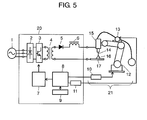
- FIG. 5 illustrates a constitution of an arc welding apparatus to be used in the embodiment 1 and an embodiment 2 of the present invention.
- the arc welding apparatus mainly includes welder 20 and robot 21.
- welder 20 an electric power from input power source 1 is rectified by primary rectifying section 2, is converted into an alternate current by switching element 3, is dropped by transformer 4, is rectified by secondary rectifying section 5 and inductor (DCL) 6, and is applied between weld wire 14 and base material 17.
- Welder 20 has output control section 7 which controls switching element 3, welding condition control section 8 which outputs a control signal to output control section 7, material setting section 9 which sets a material of weld wire 14 or a material of base material 17, and wire supply control section 11 which controls wire supply device 13.
- As the weld wire a weld wire whose material is the same as base material 17 is used.
- Robot 21 is mainly composed of manipulator 12 and robot control section 10.
- Manipulator 12 is provided with wire supply device 13 and welding torch 15.
- Material setting section 9 sets a material of base material 17, and outputs a signal corresponding to the set material to welding condition control section 8.
- Welding condition control section 8 outputs a signal for controlling the welding current at welding start period TS set for each material in advance based on the signal, a signal for controlling the welding current at steady welding period TN and a signal for controlling the welding current at welding end period TE to output control section 7.
- Output control section 7 controls switching element 3 based on the signals from welding condition control section 8 so as to control the welding current.
- Welding condition control section 8 outputs a signal for controlling the welding speed at welding start period TS set for each material in advance, a signal for controlling the welding speed at steady welding period TN and a signal for controlling the welding speed at welding end period TE to robot control section 10 based on the signal from material quality setting section 9.
- Robot control section 10 controls manipulator 12 based on the signals from welding condition control section 8 so as to control the welding speed in a welding direction of base material 17, namely, a moving speed in a welding direction of weld wire 14.
- welding condition control section 8 outputs a signal for controlling the supply speed of weld wire 14 in an integrated relationship with the welding current to wire supply control section 11, and wire supply control section 11 controls wire supply device 13 based on the signal from welding condition control section 8 so as to control the supply speed of weld wire 14.
- the welding current and the welding speed are controlled as shown in FIGS. 1A and 1B , 2A and 2B , 3A and 3B , or 4A and 4B .
- the components composing the arc welding device shown in FIG. 5 may be arranged independently or a plurality of components may be arranged compositively.
- material setting section 9 may be constituted so as to be capable of selecting the material mainly containing aluminum or the material mainly containing iron or stainless.
- arc weld is carried out at welding start period TS and/or welding end period TE with the welding current and the welding speed different from welding current IN and welding speed SN at steady welding period TN according to the intrinsic resistivity of the material of weld wire 14 or the material of base material 17.
- a uniform welding quality can be realized on the whole welding length from the welding start terminal portion to the welding end portion.
- FIGS. 2A, 2B , 4A and 4B illustrate the examples that the welding current and the welding speed are made to be constant at period TS1 of the welding start period, but the welding current and the welding speed may be controlled so as to be kept constant until weld is carried out a predetermined length from the weld start position or until predetermined time elapses from the start of the weld.
- FIGS. 4A and 4B illustrate the examples that the welding current and the welding speed are controlled constantly at period TE2 of the welding end period, but the welding current and the welding speed may be controlled so as to be kept constant for a period for which the predetermined welding length to welding end position PE is welded, or for predetermined time for which the welding reaches welding end position PE.
- the first embodiment describes the example where the welding current and the welding speed are controlled so as to change at a constant rate, namely, change in a linear pattern, but the change is not limited to linear pattern, and they may be controlled so as to change in a curved line pattern, or a linear pattern with a inflexion point or a curved line pattern with a inflection point.
- FIGS. 6A and 6B illustrate changes in the welding current and the welding speed with respect to the welding position.
- the weld starts on welding start position PS.
- the welding current is controlled at welding start period TS from welding start position PS to welding position P4 so as to be lower than welding current IN at steady welding period TN.
- the welding speed is controlled at welding start period TS so as to be lower than welding speed SN at steady welding period TN.
- the welding current is set to value IS2 lower than IN on welding start position PS.
- the welding current is controlled so as to be gradually increased from IS2 to IN at a constant rate within welding start period TS.
- the welding speed is set to value SS lower than SN on welding start position PS.
- the welding speed is controlled so as to be gradually increased from SS to SN at a constant rate within welding start period TS.
- a heat can be gradually input into the base material mainly containing iron or stainless, and the base material is gradually heated, so that the suitable penetration can be obtained.
- the welding position reaches welding position P4
- the heat has been suitably input into the base material, and the welding current becomes IN and the welding speed becomes SN in the state that the penetration is stable.
- the heat can be suitably input into the base material at the time of the start of the welding, so that uniformity of the bead width can be stably secured.
- the conventional control method Since melted metal is easily drawn to a place where the heat input is high, in the conventional control method, a heat is input into the base material excessively on welding start position PS, and the melted metal at steady welding period TN is drawn in a direction of welding start position PS. As a result, the bead width near the welding start terminal portion becomes wide and the bead on the starting portion of steady welding period TN becomes thin, namely, a constricted bead shape is formed.
- the heat can be suitably input into the base material on the welding start portion, and the melted metal at steady welding period TN is hardly drawn in the direction of welding start position PS, thereby stably securing the uniformity of the bead width.
- the control of the welding current and the welding speed is enabled similarly to the embodiment 1.
- FIGS. 7A and 7B illustrate changes in the welding current and the welding speed with respect to the welding position.
- welding start period TS is divided into period TS3 from welding start position PS to welding position P5 and period TS4 from welding position P5 to welding position P6.
- the welding current is controlled so that welding current IS2 lower than welding current IN at steady welding period TN is kept constant at period TS3, and is controlled so as to be gradually increased from IS2 to IN at a constant rate at period TS4.
- the welding speed is controlled so that welding speed SS lower than welding current IN at steady welding period TN is kept constant at period TS3, and is controlled so as to be gradually increased from SS to SN at a constant rate at period TS4.
- the heat can be input gradually, the base material is heated slowly, and the penetration, which is more suitable than the case shown in FIGS. 6A and 6B , can be obtained.
- the welding position reaches welding position P6
- the heat has been suitably input into the base material, and the welding current becomes IN and the welding speed becomes SN in the state that the penetration is stable.
- the heat can be suitably input into the base material at the time of the start of the welding, and the uniformity of the bead width can be stably secured.
- the control of the welding voltage is enabled similarly to the embodiment 1.
- the welding current and the welding speed can be controlled at the welding end period similarly to the embodiment 1.
- the arc welding control method and the arc welding apparatus of the present invention can realize the uniform welding quality, they are effective in an industrial field.
Landscapes
- Engineering & Computer Science (AREA)
- Physics & Mathematics (AREA)
- Plasma & Fusion (AREA)
- Mechanical Engineering (AREA)
- Theoretical Computer Science (AREA)
- Arc Welding In General (AREA)
Applications Claiming Priority (2)
| Application Number | Priority Date | Filing Date | Title |
|---|---|---|---|
| JP2006284538 | 2006-10-19 | ||
| PCT/JP2007/057964 WO2008047488A1 (en) | 2006-10-19 | 2007-04-11 | Method for controlling arc welding and arc welding apparatus |
Publications (3)
| Publication Number | Publication Date |
|---|---|
| EP2093009A1 true EP2093009A1 (de) | 2009-08-26 |
| EP2093009A4 EP2093009A4 (de) | 2013-05-22 |
| EP2093009B1 EP2093009B1 (de) | 2016-08-31 |
Family
ID=39313743
Family Applications (1)
| Application Number | Title | Priority Date | Filing Date |
|---|---|---|---|
| EP07741400.1A Not-in-force EP2093009B1 (de) | 2006-10-19 | 2007-04-11 | Lichtbogenschweisssteuerverfahren und lichtbogenschweissvorrichtung |
Country Status (5)
| Country | Link |
|---|---|
| US (1) | US8664568B2 (de) |
| EP (1) | EP2093009B1 (de) |
| JP (1) | JP4911033B2 (de) |
| CN (1) | CN101309773B (de) |
| WO (1) | WO2008047488A1 (de) |
Cited By (2)
| Publication number | Priority date | Publication date | Assignee | Title |
|---|---|---|---|---|
| CN102528245A (zh) * | 2010-12-28 | 2012-07-04 | 株式会社大亨 | 电弧焊接方法及电弧焊接系统 |
| EP2505294B1 (de) | 2010-10-07 | 2016-08-31 | Panasonic Intellectual Property Management Co., Ltd. | Lichtbogenschweissverfahren und lichtbogenschweissvorrichtung |
Families Citing this family (11)
| Publication number | Priority date | Publication date | Assignee | Title |
|---|---|---|---|---|
| JP5594356B2 (ja) * | 2010-09-08 | 2014-09-24 | パナソニック株式会社 | 溶接機 |
| CN102615387A (zh) * | 2012-03-02 | 2012-08-01 | 深圳麦格米特电气股份有限公司 | 一种电弧焊焊接电源控制方法 |
| EP2832486B1 (de) * | 2012-03-27 | 2017-08-30 | Panasonic Intellectual Property Management Co., Ltd. | Verfahren zur steuerung einer lichtbogenschweissung und lichtbogenschweissvorrichtung |
| FIU20140168U1 (fi) * | 2013-05-29 | 2014-12-22 | Protomet Saerkiniemi T Mi | Hitsauksen säätölaite |
| US9962785B2 (en) | 2013-12-12 | 2018-05-08 | Lincoln Global, Inc. | System and method for true electrode speed |
| CA2936412A1 (en) * | 2014-02-11 | 2015-08-20 | Magna International Inc. | Method of joining dissimilar materials |
| EP3165314A1 (de) * | 2015-11-06 | 2017-05-10 | Siegfried Plasch | Auftragsschweissverfahren |
| US11090752B2 (en) * | 2016-02-04 | 2021-08-17 | Panasonic Intellectual Property Management Co., Ltd. | Pulsed arc welding control method and pulsed arc welding device |
| CN106881530B (zh) * | 2017-03-03 | 2018-11-02 | 镇江海姆霍兹传热传动系统有限公司 | 喷涂紫铜层焊接方法 |
| JP6885112B2 (ja) * | 2017-03-07 | 2021-06-09 | 日本製鉄株式会社 | 重ねすみ肉溶接継手及び重ねすみ肉溶接継手の製造方法 |
| US11980968B2 (en) * | 2017-11-29 | 2024-05-14 | Lincoln Global, Inc. | Methods and systems for additive tool manufacturing |
Family Cites Families (13)
| Publication number | Priority date | Publication date | Assignee | Title |
|---|---|---|---|---|
| JPS57106472A (en) * | 1980-12-25 | 1982-07-02 | Nippon Steel Corp | Arc welding method |
| JPS58132374A (ja) * | 1982-01-29 | 1983-08-06 | Sumitomo Metal Ind Ltd | 管のmig溶接方法 |
| JPS6422469A (en) * | 1987-07-20 | 1989-01-25 | Nippon Kokan Kk | Automatic arc welding method |
| JPH01107968A (ja) | 1987-10-20 | 1989-04-25 | Osaka Denki Co Ltd | アーク溶接におけるクレータ処理方法 |
| US5225654A (en) * | 1992-07-15 | 1993-07-06 | The Babcock & Wilcox Company | Method for defect free keyhole plasma arc welding |
| US7032814B2 (en) * | 1999-06-21 | 2006-04-25 | Lincoln Global, Inc. | Coded welding consumable |
| JP2001259838A (ja) * | 2000-03-23 | 2001-09-25 | Daihen Corp | 交流パルスmig/mag溶接方法及び電源装置 |
| JP4846898B2 (ja) * | 2000-09-12 | 2011-12-28 | 株式会社ダイヘン | 交流パルスアーク溶接制御方法及び溶接電源装置 |
| AT411878B (de) * | 2000-10-17 | 2004-07-26 | Fronius Schweissmasch Prod | Verfahren zum steuern und/oder regeln eines schweissprozesses |
| JP4490011B2 (ja) | 2001-11-13 | 2010-06-23 | 株式会社ダイヘン | アークスタート制御方法 |
| JP2004174523A (ja) * | 2002-11-25 | 2004-06-24 | Toyota Motor Corp | アーク溶接の制御方法 |
| JP2006198668A (ja) * | 2005-01-24 | 2006-08-03 | Daihen Corp | アーク溶接電源の出力制御方法 |
| US7271365B2 (en) * | 2005-04-11 | 2007-09-18 | Lincoln Global, Inc. | System and method for pulse welding |
-
2007
- 2007-04-11 WO PCT/JP2007/057964 patent/WO2008047488A1/ja not_active Ceased
- 2007-04-11 US US11/911,387 patent/US8664568B2/en not_active Expired - Fee Related
- 2007-04-11 EP EP07741400.1A patent/EP2093009B1/de not_active Not-in-force
- 2007-04-11 CN CN2007800001695A patent/CN101309773B/zh not_active Expired - Fee Related
- 2007-04-11 JP JP2007540409A patent/JP4911033B2/ja not_active Expired - Fee Related
Cited By (3)
| Publication number | Priority date | Publication date | Assignee | Title |
|---|---|---|---|---|
| EP2505294B1 (de) | 2010-10-07 | 2016-08-31 | Panasonic Intellectual Property Management Co., Ltd. | Lichtbogenschweissverfahren und lichtbogenschweissvorrichtung |
| CN102528245A (zh) * | 2010-12-28 | 2012-07-04 | 株式会社大亨 | 电弧焊接方法及电弧焊接系统 |
| CN102528245B (zh) * | 2010-12-28 | 2016-04-20 | 株式会社大亨 | 电弧焊接方法及电弧焊接系统 |
Also Published As
| Publication number | Publication date |
|---|---|
| WO2008047488A1 (en) | 2008-04-24 |
| US8664568B2 (en) | 2014-03-04 |
| CN101309773A (zh) | 2008-11-19 |
| CN101309773B (zh) | 2012-07-18 |
| JP4911033B2 (ja) | 2012-04-04 |
| US20090289044A1 (en) | 2009-11-26 |
| EP2093009A4 (de) | 2013-05-22 |
| EP2093009B1 (de) | 2016-08-31 |
| JPWO2008047488A1 (ja) | 2010-02-18 |
Similar Documents
| Publication | Publication Date | Title |
|---|---|---|
| EP2093009B1 (de) | Lichtbogenschweisssteuerverfahren und lichtbogenschweissvorrichtung | |
| EP3194103B1 (de) | Elektrodennegatives impulsschweisssystem und verfahren | |
| EP2969348B1 (de) | Elektrodennegatives impulsschweisssystem und verfahren | |
| US11813704B2 (en) | Pulsed arc welding control method and pulsed arc welding device | |
| US5225660A (en) | Consumable-electrode ac gas shield arc welding method and apparatus therefor | |
| EP3530395B1 (de) | Steuerungsverfahren für ac-impulslichtbogenschweissen | |
| US10786862B2 (en) | Pulse arc welding control method and pulse arc welding device | |
| EP2210694A1 (de) | Pulslichtbogenschweißverfahren | |
| JP4715813B2 (ja) | パルスアーク溶接制御方法およびパルスアーク溶接装置 | |
| JP6994623B2 (ja) | アークスタート方法 | |
| KR102493386B1 (ko) | 소모성 전극으로 용접 공정을 제어하기 위한 방법 및 이 유형의 제어기를 갖는 용접 장치 | |
| KR20260012717A (ko) | 다중 아크 접합 방법 | |
| CN107350606B (zh) | 脉冲控制的方法及电焊机 | |
| JP2003019563A (ja) | アルミニウム系スタッドの溶接方法及び装置 | |
| JP2022144100A (ja) | アーク溶接装置及びアーク溶接方法 |
Legal Events
| Date | Code | Title | Description |
|---|---|---|---|
| PUAI | Public reference made under article 153(3) epc to a published international application that has entered the european phase |
Free format text: ORIGINAL CODE: 0009012 |
|
| 17P | Request for examination filed |
Effective date: 20071011 |
|
| AK | Designated contracting states |
Kind code of ref document: A1 Designated state(s): AT BE BG CH CY CZ DE DK EE ES FI FR GB GR HU IE IS IT LI LT LU LV MC MT NL PL PT RO SE SI SK TR |
|
| DAX | Request for extension of the european patent (deleted) | ||
| A4 | Supplementary search report drawn up and despatched |
Effective date: 20130422 |
|
| RIC1 | Information provided on ipc code assigned before grant |
Ipc: B23K 9/067 20060101ALI20130416BHEP Ipc: B23K 9/10 20060101ALI20130416BHEP Ipc: B23K 9/00 20060101AFI20130416BHEP |
|
| 17Q | First examination report despatched |
Effective date: 20140527 |
|
| RAP1 | Party data changed (applicant data changed or rights of an application transferred) |
Owner name: PANASONIC INTELLECTUAL PROPERTY MANAGEMENT CO., LT |
|
| RAP1 | Party data changed (applicant data changed or rights of an application transferred) |
Owner name: PANASONIC INTELLECTUAL PROPERTY MANAGEMENT CO., LT |
|
| GRAP | Despatch of communication of intention to grant a patent |
Free format text: ORIGINAL CODE: EPIDOSNIGR1 |
|
| INTG | Intention to grant announced |
Effective date: 20160621 |
|
| GRAS | Grant fee paid |
Free format text: ORIGINAL CODE: EPIDOSNIGR3 |
|
| GRAA | (expected) grant |
Free format text: ORIGINAL CODE: 0009210 |
|
| AK | Designated contracting states |
Kind code of ref document: B1 Designated state(s): AT BE BG CH CY CZ DE DK EE ES FI FR GB GR HU IE IS IT LI LT LU LV MC MT NL PL PT RO SE SI SK TR |
|
| REG | Reference to a national code |
Ref country code: CH Ref legal event code: EP Ref country code: GB Ref legal event code: FG4D |
|
| REG | Reference to a national code |
Ref country code: IE Ref legal event code: FG4D |
|
| REG | Reference to a national code |
Ref country code: DE Ref legal event code: R096 Ref document number: 602007047723 Country of ref document: DE |
|
| REG | Reference to a national code |
Ref country code: AT Ref legal event code: REF Ref document number: 824561 Country of ref document: AT Kind code of ref document: T Effective date: 20161015 |
|
| REG | Reference to a national code |
Ref country code: LT Ref legal event code: MG4D |
|
| REG | Reference to a national code |
Ref country code: NL Ref legal event code: MP Effective date: 20160831 |
|
| REG | Reference to a national code |
Ref country code: AT Ref legal event code: MK05 Ref document number: 824561 Country of ref document: AT Kind code of ref document: T Effective date: 20160831 |
|
| PG25 | Lapsed in a contracting state [announced via postgrant information from national office to epo] |
Ref country code: LT Free format text: LAPSE BECAUSE OF FAILURE TO SUBMIT A TRANSLATION OF THE DESCRIPTION OR TO PAY THE FEE WITHIN THE PRESCRIBED TIME-LIMIT Effective date: 20160831 Ref country code: FI Free format text: LAPSE BECAUSE OF FAILURE TO SUBMIT A TRANSLATION OF THE DESCRIPTION OR TO PAY THE FEE WITHIN THE PRESCRIBED TIME-LIMIT Effective date: 20160831 |
|
| REG | Reference to a national code |
Ref country code: DE Ref legal event code: R084 Ref document number: 602007047723 Country of ref document: DE |
|
| PG25 | Lapsed in a contracting state [announced via postgrant information from national office to epo] |
Ref country code: ES Free format text: LAPSE BECAUSE OF FAILURE TO SUBMIT A TRANSLATION OF THE DESCRIPTION OR TO PAY THE FEE WITHIN THE PRESCRIBED TIME-LIMIT Effective date: 20160831 Ref country code: LV Free format text: LAPSE BECAUSE OF FAILURE TO SUBMIT A TRANSLATION OF THE DESCRIPTION OR TO PAY THE FEE WITHIN THE PRESCRIBED TIME-LIMIT Effective date: 20160831 Ref country code: SE Free format text: LAPSE BECAUSE OF FAILURE TO SUBMIT A TRANSLATION OF THE DESCRIPTION OR TO PAY THE FEE WITHIN THE PRESCRIBED TIME-LIMIT Effective date: 20160831 Ref country code: GR Free format text: LAPSE BECAUSE OF FAILURE TO SUBMIT A TRANSLATION OF THE DESCRIPTION OR TO PAY THE FEE WITHIN THE PRESCRIBED TIME-LIMIT Effective date: 20161201 Ref country code: AT Free format text: LAPSE BECAUSE OF FAILURE TO SUBMIT A TRANSLATION OF THE DESCRIPTION OR TO PAY THE FEE WITHIN THE PRESCRIBED TIME-LIMIT Effective date: 20160831 Ref country code: NL Free format text: LAPSE BECAUSE OF FAILURE TO SUBMIT A TRANSLATION OF THE DESCRIPTION OR TO PAY THE FEE WITHIN THE PRESCRIBED TIME-LIMIT Effective date: 20160831 |
|
| PG25 | Lapsed in a contracting state [announced via postgrant information from national office to epo] |
Ref country code: RO Free format text: LAPSE BECAUSE OF FAILURE TO SUBMIT A TRANSLATION OF THE DESCRIPTION OR TO PAY THE FEE WITHIN THE PRESCRIBED TIME-LIMIT Effective date: 20160831 Ref country code: EE Free format text: LAPSE BECAUSE OF FAILURE TO SUBMIT A TRANSLATION OF THE DESCRIPTION OR TO PAY THE FEE WITHIN THE PRESCRIBED TIME-LIMIT Effective date: 20160831 |
|
| PG25 | Lapsed in a contracting state [announced via postgrant information from national office to epo] |
Ref country code: BG Free format text: LAPSE BECAUSE OF FAILURE TO SUBMIT A TRANSLATION OF THE DESCRIPTION OR TO PAY THE FEE WITHIN THE PRESCRIBED TIME-LIMIT Effective date: 20161130 Ref country code: PT Free format text: LAPSE BECAUSE OF FAILURE TO SUBMIT A TRANSLATION OF THE DESCRIPTION OR TO PAY THE FEE WITHIN THE PRESCRIBED TIME-LIMIT Effective date: 20170102 Ref country code: BE Free format text: LAPSE BECAUSE OF FAILURE TO SUBMIT A TRANSLATION OF THE DESCRIPTION OR TO PAY THE FEE WITHIN THE PRESCRIBED TIME-LIMIT Effective date: 20160831 Ref country code: SK Free format text: LAPSE BECAUSE OF FAILURE TO SUBMIT A TRANSLATION OF THE DESCRIPTION OR TO PAY THE FEE WITHIN THE PRESCRIBED TIME-LIMIT Effective date: 20160831 Ref country code: PL Free format text: LAPSE BECAUSE OF FAILURE TO SUBMIT A TRANSLATION OF THE DESCRIPTION OR TO PAY THE FEE WITHIN THE PRESCRIBED TIME-LIMIT Effective date: 20160831 Ref country code: DK Free format text: LAPSE BECAUSE OF FAILURE TO SUBMIT A TRANSLATION OF THE DESCRIPTION OR TO PAY THE FEE WITHIN THE PRESCRIBED TIME-LIMIT Effective date: 20160831 Ref country code: CZ Free format text: LAPSE BECAUSE OF FAILURE TO SUBMIT A TRANSLATION OF THE DESCRIPTION OR TO PAY THE FEE WITHIN THE PRESCRIBED TIME-LIMIT Effective date: 20160831 |
|
| REG | Reference to a national code |
Ref country code: DE Ref legal event code: R097 Ref document number: 602007047723 Country of ref document: DE |
|
| PG25 | Lapsed in a contracting state [announced via postgrant information from national office to epo] |
Ref country code: IT Free format text: LAPSE BECAUSE OF FAILURE TO SUBMIT A TRANSLATION OF THE DESCRIPTION OR TO PAY THE FEE WITHIN THE PRESCRIBED TIME-LIMIT Effective date: 20160831 |
|
| PLBE | No opposition filed within time limit |
Free format text: ORIGINAL CODE: 0009261 |
|
| STAA | Information on the status of an ep patent application or granted ep patent |
Free format text: STATUS: NO OPPOSITION FILED WITHIN TIME LIMIT |
|
| 26N | No opposition filed |
Effective date: 20170601 |
|
| PG25 | Lapsed in a contracting state [announced via postgrant information from national office to epo] |
Ref country code: SI Free format text: LAPSE BECAUSE OF FAILURE TO SUBMIT A TRANSLATION OF THE DESCRIPTION OR TO PAY THE FEE WITHIN THE PRESCRIBED TIME-LIMIT Effective date: 20160831 |
|
| REG | Reference to a national code |
Ref country code: CH Ref legal event code: PL |
|
| GBPC | Gb: european patent ceased through non-payment of renewal fee |
Effective date: 20170411 |
|
| REG | Reference to a national code |
Ref country code: IE Ref legal event code: MM4A |
|
| REG | Reference to a national code |
Ref country code: FR Ref legal event code: ST Effective date: 20171229 |
|
| PG25 | Lapsed in a contracting state [announced via postgrant information from national office to epo] |
Ref country code: MC Free format text: LAPSE BECAUSE OF FAILURE TO SUBMIT A TRANSLATION OF THE DESCRIPTION OR TO PAY THE FEE WITHIN THE PRESCRIBED TIME-LIMIT Effective date: 20160831 Ref country code: FR Free format text: LAPSE BECAUSE OF NON-PAYMENT OF DUE FEES Effective date: 20170502 |
|
| PG25 | Lapsed in a contracting state [announced via postgrant information from national office to epo] |
Ref country code: GB Free format text: LAPSE BECAUSE OF NON-PAYMENT OF DUE FEES Effective date: 20170411 Ref country code: LU Free format text: LAPSE BECAUSE OF NON-PAYMENT OF DUE FEES Effective date: 20170411 Ref country code: LI Free format text: LAPSE BECAUSE OF NON-PAYMENT OF DUE FEES Effective date: 20170430 Ref country code: CH Free format text: LAPSE BECAUSE OF NON-PAYMENT OF DUE FEES Effective date: 20170430 |
|
| PG25 | Lapsed in a contracting state [announced via postgrant information from national office to epo] |
Ref country code: IE Free format text: LAPSE BECAUSE OF NON-PAYMENT OF DUE FEES Effective date: 20170411 |
|
| PG25 | Lapsed in a contracting state [announced via postgrant information from national office to epo] |
Ref country code: MT Free format text: LAPSE BECAUSE OF NON-PAYMENT OF DUE FEES Effective date: 20170411 |
|
| PG25 | Lapsed in a contracting state [announced via postgrant information from national office to epo] |
Ref country code: HU Free format text: LAPSE BECAUSE OF FAILURE TO SUBMIT A TRANSLATION OF THE DESCRIPTION OR TO PAY THE FEE WITHIN THE PRESCRIBED TIME-LIMIT; INVALID AB INITIO Effective date: 20070411 |
|
| PGFP | Annual fee paid to national office [announced via postgrant information from national office to epo] |
Ref country code: DE Payment date: 20190418 Year of fee payment: 13 |
|
| PG25 | Lapsed in a contracting state [announced via postgrant information from national office to epo] |
Ref country code: CY Free format text: LAPSE BECAUSE OF NON-PAYMENT OF DUE FEES Effective date: 20160831 |
|
| PG25 | Lapsed in a contracting state [announced via postgrant information from national office to epo] |
Ref country code: TR Free format text: LAPSE BECAUSE OF FAILURE TO SUBMIT A TRANSLATION OF THE DESCRIPTION OR TO PAY THE FEE WITHIN THE PRESCRIBED TIME-LIMIT Effective date: 20160831 |
|
| PG25 | Lapsed in a contracting state [announced via postgrant information from national office to epo] |
Ref country code: IS Free format text: LAPSE BECAUSE OF FAILURE TO SUBMIT A TRANSLATION OF THE DESCRIPTION OR TO PAY THE FEE WITHIN THE PRESCRIBED TIME-LIMIT Effective date: 20161231 |
|
| REG | Reference to a national code |
Ref country code: DE Ref legal event code: R119 Ref document number: 602007047723 Country of ref document: DE |
|
| PG25 | Lapsed in a contracting state [announced via postgrant information from national office to epo] |
Ref country code: DE Free format text: LAPSE BECAUSE OF NON-PAYMENT OF DUE FEES Effective date: 20201103 |