EP2093012A2 - Méthode et outil pour l'usinage d'un anneau d'un rotor d'une turbine à gaz avec des aubes integrées - Google Patents
Méthode et outil pour l'usinage d'un anneau d'un rotor d'une turbine à gaz avec des aubes integrées Download PDFInfo
- Publication number
- EP2093012A2 EP2093012A2 EP09152591A EP09152591A EP2093012A2 EP 2093012 A2 EP2093012 A2 EP 2093012A2 EP 09152591 A EP09152591 A EP 09152591A EP 09152591 A EP09152591 A EP 09152591A EP 2093012 A2 EP2093012 A2 EP 2093012A2
- Authority
- EP
- European Patent Office
- Prior art keywords
- annulus
- blades
- milling
- tool
- processing
- Prior art date
- Legal status (The legal status is an assumption and is not a legal conclusion. Google has not performed a legal analysis and makes no representation as to the accuracy of the status listed.)
- Granted
Links
- 238000000034 method Methods 0.000 title claims abstract description 14
- 238000003754 machining Methods 0.000 title claims description 12
- 238000003801 milling Methods 0.000 claims abstract description 29
- 238000005520 cutting process Methods 0.000 claims abstract description 20
- 239000000463 material Substances 0.000 claims abstract description 7
- 230000007704 transition Effects 0.000 claims description 5
- 230000002093 peripheral effect Effects 0.000 claims description 3
- 238000003672 processing method Methods 0.000 abstract description 2
- 238000003466 welding Methods 0.000 description 2
- 238000001311 chemical methods and process Methods 0.000 description 1
- 238000007796 conventional method Methods 0.000 description 1
- 230000001419 dependent effect Effects 0.000 description 1
- 238000004519 manufacturing process Methods 0.000 description 1
- 238000007493 shaping process Methods 0.000 description 1
- 239000002689 soil Substances 0.000 description 1
Images
Classifications
-
- B—PERFORMING OPERATIONS; TRANSPORTING
- B23—MACHINE TOOLS; METAL-WORKING NOT OTHERWISE PROVIDED FOR
- B23P—METAL-WORKING NOT OTHERWISE PROVIDED FOR; COMBINED OPERATIONS; UNIVERSAL MACHINE TOOLS
- B23P15/00—Making specific metal objects by operations not covered by a single other subclass or a group in this subclass
- B23P15/006—Making specific metal objects by operations not covered by a single other subclass or a group in this subclass turbine wheels
-
- B—PERFORMING OPERATIONS; TRANSPORTING
- B23—MACHINE TOOLS; METAL-WORKING NOT OTHERWISE PROVIDED FOR
- B23C—MILLING
- B23C3/00—Milling particular work; Special milling operations; Machines therefor
- B23C3/16—Working surfaces curved in two directions
- B23C3/18—Working surfaces curved in two directions for shaping screw-propellers, turbine blades, or impellers
-
- B—PERFORMING OPERATIONS; TRANSPORTING
- B23—MACHINE TOOLS; METAL-WORKING NOT OTHERWISE PROVIDED FOR
- B23C—MILLING
- B23C5/00—Milling-cutters
- B23C5/006—Details of the milling cutter body
-
- B—PERFORMING OPERATIONS; TRANSPORTING
- B23—MACHINE TOOLS; METAL-WORKING NOT OTHERWISE PROVIDED FOR
- B23C—MILLING
- B23C5/00—Milling-cutters
- B23C5/02—Milling-cutters characterised by the shape of the cutter
- B23C5/10—Shank-type cutters, i.e. with an integral shaft
-
- F—MECHANICAL ENGINEERING; LIGHTING; HEATING; WEAPONS; BLASTING
- F01—MACHINES OR ENGINES IN GENERAL; ENGINE PLANTS IN GENERAL; STEAM ENGINES
- F01D—NON-POSITIVE DISPLACEMENT MACHINES OR ENGINES, e.g. STEAM TURBINES
- F01D5/00—Blades; Blade-carrying members; Heating, heat-insulating, cooling or antivibration means on the blades or the members
- F01D5/34—Rotor-blade aggregates of unitary construction, e.g. formed of sheet laminae
-
- B—PERFORMING OPERATIONS; TRANSPORTING
- B23—MACHINE TOOLS; METAL-WORKING NOT OTHERWISE PROVIDED FOR
- B23C—MILLING
- B23C2215/00—Details of workpieces
- B23C2215/52—Axial turbine wheels
-
- Y—GENERAL TAGGING OF NEW TECHNOLOGICAL DEVELOPMENTS; GENERAL TAGGING OF CROSS-SECTIONAL TECHNOLOGIES SPANNING OVER SEVERAL SECTIONS OF THE IPC; TECHNICAL SUBJECTS COVERED BY FORMER USPC CROSS-REFERENCE ART COLLECTIONS [XRACs] AND DIGESTS
- Y10—TECHNICAL SUBJECTS COVERED BY FORMER USPC
- Y10T—TECHNICAL SUBJECTS COVERED BY FORMER US CLASSIFICATION
- Y10T29/00—Metal working
- Y10T29/49—Method of mechanical manufacture
- Y10T29/49316—Impeller making
- Y10T29/4932—Turbomachine making
- Y10T29/49325—Shaping integrally bladed rotor
-
- Y—GENERAL TAGGING OF NEW TECHNOLOGICAL DEVELOPMENTS; GENERAL TAGGING OF CROSS-SECTIONAL TECHNOLOGIES SPANNING OVER SEVERAL SECTIONS OF THE IPC; TECHNICAL SUBJECTS COVERED BY FORMER USPC CROSS-REFERENCE ART COLLECTIONS [XRACs] AND DIGESTS
- Y10—TECHNICAL SUBJECTS COVERED BY FORMER USPC
- Y10T—TECHNICAL SUBJECTS COVERED BY FORMER US CLASSIFICATION
- Y10T407/00—Cutters, for shaping
- Y10T407/19—Rotary cutting tool
-
- Y—GENERAL TAGGING OF NEW TECHNOLOGICAL DEVELOPMENTS; GENERAL TAGGING OF CROSS-SECTIONAL TECHNOLOGIES SPANNING OVER SEVERAL SECTIONS OF THE IPC; TECHNICAL SUBJECTS COVERED BY FORMER USPC CROSS-REFERENCE ART COLLECTIONS [XRACs] AND DIGESTS
- Y10—TECHNICAL SUBJECTS COVERED BY FORMER USPC
- Y10T—TECHNICAL SUBJECTS COVERED BY FORMER US CLASSIFICATION
- Y10T407/00—Cutters, for shaping
- Y10T407/19—Rotary cutting tool
- Y10T407/1946—Face or end mill
- Y10T407/1948—Face or end mill with cutting edge entirely across end of tool [e.g., router bit, end mill, etc.]
-
- Y—GENERAL TAGGING OF NEW TECHNOLOGICAL DEVELOPMENTS; GENERAL TAGGING OF CROSS-SECTIONAL TECHNOLOGIES SPANNING OVER SEVERAL SECTIONS OF THE IPC; TECHNICAL SUBJECTS COVERED BY FORMER USPC CROSS-REFERENCE ART COLLECTIONS [XRACs] AND DIGESTS
- Y10—TECHNICAL SUBJECTS COVERED BY FORMER USPC
- Y10T—TECHNICAL SUBJECTS COVERED BY FORMER US CLASSIFICATION
- Y10T409/00—Gear cutting, milling, or planing
- Y10T409/30—Milling
- Y10T409/303752—Process
-
- Y—GENERAL TAGGING OF NEW TECHNOLOGICAL DEVELOPMENTS; GENERAL TAGGING OF CROSS-SECTIONAL TECHNOLOGIES SPANNING OVER SEVERAL SECTIONS OF THE IPC; TECHNICAL SUBJECTS COVERED BY FORMER USPC CROSS-REFERENCE ART COLLECTIONS [XRACs] AND DIGESTS
- Y10—TECHNICAL SUBJECTS COVERED BY FORMER USPC
- Y10T—TECHNICAL SUBJECTS COVERED BY FORMER US CLASSIFICATION
- Y10T409/00—Gear cutting, milling, or planing
- Y10T409/30—Milling
- Y10T409/303752—Process
- Y10T409/303808—Process including infeeding
Definitions
- the invention relates to a method for Annulusbearbeitung in a gas turbine rotor with integrally formed blades and a tool for performing the method.
- Gas turbine rotors and in particular the rotors of gas turbine engine compressors, are designed with a blading integrally formed on the annular outer periphery of a disk for reliability, weight saving, power enhancement, and durability.
- Such components are referred to as blisks, the term blisk being a shorthand of the English language term "blade integrated disk”.
- the production of blisks is known to be carried out by welding, in particular friction welding, separately manufactured blades with the peripheral ring surface of the preferably forged disc or by emanating from the outer ring surface of the disc material removal by means of cutting or chemical processes.
- annulus After shaping the blades with the known material removal methods, a fine machining of the blade surfaces and edges as well as of the soil remaining between the blades after removal of the material takes place, referred to as annulus. Due to the small distance between the adjacent blades and the complicated and also different curvature and rotation of the vanes on the pressure side and the suction side, the annulus far away from the blade tips and the transition area (fillet) between the annulus and the blade side surfaces become a crowned tip edited copy router edited.
- ball nose Cutter or die cutter with conical cutting part after the ball tip can be made in the gap formed between two adjacent blades, respectively, so that the side surface of the copying cutter does not collide with the side surfaces of the blades whose crowned tip must be guided in a plurality of adjacent tracks over the annulus, on the one hand very time consuming and produces on the other juxtaposed sickle-shaped processing tracks on the annulus surface with high roughness or profile deviation, so that the blisk with respect to the aerodynamic properties high requirements does justice.
- the invention has for its object to provide a method for finishing the present between two blades of a Blisk Annulus and a corresponding tool for performing the method so that the processing time and tool wear are reduced and a flat Annulus Formation with low shape or profile deviation, the high aerodynamic requirements are sufficient.
- the basic idea of the invention is that the removal of material takes place on the annulus on a wide planar processing path with the frontal cutting surface of a substantially cylindrical milling head.
- This type of editing can with a reduced number of processing paths that overlap one another, a substantially flat, smooth annulus surface is achieved.
- the time required for Annulibeabeitung is reduced and the tool wear reduced.
- the surface condition of the annulus may also be improved because of the improved conditions for chip removal so that the integrally bladed rotor meets high aerodynamic performance requirements.
- the maximum processing width is smaller than the smallest distance between the opposite fillets of the blades and may be greater than half the smallest fillet distance, so that even on two overlapping processing paths the annulus and the respective transition area (fillet) can be machined completely to the blade side surface ,
- the milling tool according to the invention for carrying out the method has a provided on a tool shank, substantially cylindrical milling head with a flat frontal cutting area and correspondingly straight cutting.
- the diameter of the tool shank is reduced in the area lying between the blades during machining so that it does not collide with the blade surfaces during machining performed in a constant position.
- the circumferential side surface of the milling head is concavely curved and has correspondingly curved cutting edges.
- the curved side surface serves to avoid sharp edges.
- the diameter of the milling head is smaller than the smallest distance between the opposite fillets and preferably greater than half the smallest distance between the two fillets.
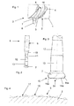
- Fig. 1 shows, on the circular outer circumferential surface 1 of the disc 2 of a blisk 3 differently curved and twisted blades 4 integrally formed.
- the portion of the outer peripheral surface of the disc 2 remaining between the blades 4 is the annulus 5 which is provided with a milling tool for achieving its final contour in the planar region and the transition region 16 (fillet) to the blade surfaces on two machining paths 8 (in the present embodiment) 6 with the end face flat (straight) and rounded on the curved side surface outwardly extending cutting on the milling head 7 is processed.
- the milling head 7 rotating during machining and movable along the machining paths 8 is connected to a drive means (not shown).
- the tool shank 9 in the reduced diameter portion first has a conically tapered portion 10, followed by a straight portion 11, then a conically enlarged portion 12, and then back to the milling head 7 again a straight portion 13.
- the milling head 7 has at the flat cutting area 14 (end face) straight cutting edges 14a and at the toroidal circumferential lateral cutting surface 15 correspondingly curved cutting edges 15a, the curvature of which may correspond to the rounding in the fillet 16.
- the maximum diameter of the milling head 7 is slightly smaller than the smallest distance between the blades 4 in the region of the fillet 16, but greater than half the maximum distance between the blades 4 in the region of the fillet 16.
- the annulus 5 and the fillet 16 can thus be processed on only two - overlapping in the middle - processing paths 8 finished with little time.
- the achieved surface profile 17 is - how Fig. 4 shows - compared to achieved with the conventional method and tool surface structure 18 is substantially flat and smooth.
- the surface condition can also be improved because of the improved conditions for chip removal. Due to the significantly reduced number of machining paths, tool wear is significantly reduced.
Landscapes
- Engineering & Computer Science (AREA)
- Mechanical Engineering (AREA)
- Ceramic Engineering (AREA)
- General Engineering & Computer Science (AREA)
- Milling Processes (AREA)
- Structures Of Non-Positive Displacement Pumps (AREA)
- Turbine Rotor Nozzle Sealing (AREA)
Applications Claiming Priority (1)
| Application Number | Priority Date | Filing Date | Title |
|---|---|---|---|
| DE102008010252A DE102008010252A1 (de) | 2008-02-20 | 2008-02-20 | Verfahren und Werkzeug zur Annulusbearbeitung eines Gasturbinenrotors mit integral angeformten Schaufeln |
Publications (3)
| Publication Number | Publication Date |
|---|---|
| EP2093012A2 true EP2093012A2 (fr) | 2009-08-26 |
| EP2093012A3 EP2093012A3 (fr) | 2009-09-30 |
| EP2093012B1 EP2093012B1 (fr) | 2011-12-21 |
Family
ID=40718566
Family Applications (1)
| Application Number | Title | Priority Date | Filing Date |
|---|---|---|---|
| EP09152591A Not-in-force EP2093012B1 (fr) | 2008-02-20 | 2009-02-11 | Méthode pour l'usinage d'un anneau d'un rotor d'une turbine à gaz avec des aubes integrées |
Country Status (3)
| Country | Link |
|---|---|
| US (1) | US7704021B2 (fr) |
| EP (1) | EP2093012B1 (fr) |
| DE (1) | DE102008010252A1 (fr) |
Cited By (3)
| Publication number | Priority date | Publication date | Assignee | Title |
|---|---|---|---|---|
| CN104475842A (zh) * | 2014-11-24 | 2015-04-01 | 四川成发航空科技股份有限公司 | 一种整体叶盘结构型面铣削加工工艺方法 |
| CN106271463A (zh) * | 2016-09-29 | 2017-01-04 | 天津机电职业技术学院 | 一种分度凸轮的加工方法 |
| WO2020228882A1 (fr) * | 2019-05-13 | 2020-11-19 | Schaeffler Technologies AG & Co. KG | Outil de fraisage et procédé de fabrication d'une cage de palier à roulement |
Families Citing this family (11)
| Publication number | Priority date | Publication date | Assignee | Title |
|---|---|---|---|---|
| US8100655B2 (en) * | 2008-03-28 | 2012-01-24 | Pratt & Whitney Canada Corp. | Method of machining airfoil root fillets |
| CN102528138B (zh) * | 2010-12-24 | 2014-01-08 | 沈阳黎明航空发动机(集团)有限责任公司 | 一种采用鼓形刀的复杂曲面加工方法 |
| US20130000121A1 (en) * | 2011-06-30 | 2013-01-03 | Gregory Mark Burgess | Spherical cutter and method for machining a curved slot |
| US8904636B2 (en) | 2011-07-22 | 2014-12-09 | Pratt & Whitney Canada Corp. | Method of fabricating integrally bladed rotor using surface positioning in relation to surface priority |
| US8844132B2 (en) | 2011-07-22 | 2014-09-30 | Pratt & Whitney Canada Corp. | Method of machining using an automatic tool path generator adapted to individual blade surfaces on an integrally bladed rotor |
| US8788083B2 (en) | 2011-07-22 | 2014-07-22 | Pratt & Whitney Canada Corp. | Compensation for process variables in a numerically-controlled machining operation |
| US8631577B2 (en) | 2011-07-22 | 2014-01-21 | Pratt & Whitney Canada Corp. | Method of fabricating integrally bladed rotor and stator vane assembly |
| US20170089202A1 (en) * | 2015-09-29 | 2017-03-30 | United Technologies Corporation | Flow path trenches and methods of forming the same |
| DE102016117932B4 (de) * | 2016-09-22 | 2020-06-10 | Open Mind Technologies Ag | Verfahren zur materialabtragenden Bearbeitung von Verrundungsflächen eines Werkstückes |
| JP7121770B2 (ja) * | 2020-03-31 | 2022-08-18 | 株式会社牧野フライス製作所 | 切削工具及びワークの加工方法 |
| CN111958194B (zh) * | 2020-08-18 | 2022-02-25 | 哈尔滨汽轮机厂有限责任公司 | 一种带预扭角叶片叶冠汽封齿加工方法 |
Citations (2)
| Publication number | Priority date | Publication date | Assignee | Title |
|---|---|---|---|---|
| DE317586C (fr) | ||||
| EP0992310A2 (fr) | 1998-10-05 | 2000-04-12 | General Electric Company | Méthode de fraisage à multiple pas |
Family Cites Families (14)
| Publication number | Priority date | Publication date | Assignee | Title |
|---|---|---|---|---|
| US2585973A (en) * | 1948-04-01 | 1952-02-19 | Thompson Prod Inc | Milling machine and method for impeller wheel manufacture |
| US2662450A (en) * | 1948-11-26 | 1953-12-15 | Thompson Prod Inc | Machine for milling impeller wheels |
| US4536932A (en) * | 1982-11-22 | 1985-08-27 | United Technologies Corporation | Method for eliminating low cycle fatigue cracking in integrally bladed disks |
| JPS6144521A (ja) * | 1984-08-02 | 1986-03-04 | Mitsubishi Heavy Ind Ltd | 薄肉曲面加工法 |
| SU1502230A1 (ru) * | 1987-10-19 | 1989-08-23 | Предприятие П/Я Р-6564 | Способ обработки нежестких деталей |
| FR2635478B1 (fr) * | 1988-08-19 | 1993-07-09 | Chasset Jean Pierre | Outil de coupe rotatif a surfacer et rainurer de type fraise |
| US5122966A (en) * | 1989-09-18 | 1992-06-16 | Northern Research & Engineering | Computer generated tool path interference check method |
| JP4354091B2 (ja) * | 2000-05-23 | 2009-10-28 | 三菱重工業株式会社 | タービンロータ翼溝切削工具及びタービンロータ翼溝切削方法 |
| US6684742B1 (en) | 2000-10-19 | 2004-02-03 | Keith Alan White | Machining apparatuses and methods of use |
| ITMI20021876A1 (it) * | 2002-09-03 | 2004-03-04 | Nuovo Pignone Spa | Procedimento migliorato per realizzare un rotore di un |
| DE10312224B3 (de) | 2003-03-19 | 2004-10-28 | Mtu Aero Engines Gmbh | Verfahren zum Herstellen von strömungsbeaufschlagten Bauteilen |
| KR100558617B1 (ko) * | 2003-04-22 | 2006-03-13 | 한국항공우주산업 주식회사 | 카운터 엔드밀을 이용한 카운터 보어 형성방법 |
| US7927189B2 (en) * | 2004-08-16 | 2011-04-19 | United Technologies Corporation | Superabrasive tool |
| DE102008019332A1 (de) * | 2008-04-16 | 2009-10-22 | Rolls-Royce Deutschland Ltd & Co Kg | Verfahren zum Fräsen von Blisks |
-
2008
- 2008-02-20 DE DE102008010252A patent/DE102008010252A1/de not_active Withdrawn
-
2009
- 2009-02-11 EP EP09152591A patent/EP2093012B1/fr not_active Not-in-force
- 2009-02-19 US US12/379,377 patent/US7704021B2/en not_active Expired - Fee Related
Patent Citations (2)
| Publication number | Priority date | Publication date | Assignee | Title |
|---|---|---|---|---|
| DE317586C (fr) | ||||
| EP0992310A2 (fr) | 1998-10-05 | 2000-04-12 | General Electric Company | Méthode de fraisage à multiple pas |
Cited By (5)
| Publication number | Priority date | Publication date | Assignee | Title |
|---|---|---|---|---|
| CN104475842A (zh) * | 2014-11-24 | 2015-04-01 | 四川成发航空科技股份有限公司 | 一种整体叶盘结构型面铣削加工工艺方法 |
| CN104475842B (zh) * | 2014-11-24 | 2016-08-24 | 四川成发航空科技股份有限公司 | 一种整体叶盘结构型面铣削加工工艺方法 |
| CN106271463A (zh) * | 2016-09-29 | 2017-01-04 | 天津机电职业技术学院 | 一种分度凸轮的加工方法 |
| WO2020228882A1 (fr) * | 2019-05-13 | 2020-11-19 | Schaeffler Technologies AG & Co. KG | Outil de fraisage et procédé de fabrication d'une cage de palier à roulement |
| US12290865B2 (en) | 2019-05-13 | 2025-05-06 | Schaeffler Technologies AG & Co. KG | Milling tool and method for producing a rolling bearing cage |
Also Published As
| Publication number | Publication date |
|---|---|
| US20090245959A1 (en) | 2009-10-01 |
| EP2093012B1 (fr) | 2011-12-21 |
| DE102008010252A1 (de) | 2009-08-27 |
| EP2093012A3 (fr) | 2009-09-30 |
| US7704021B2 (en) | 2010-04-27 |
Similar Documents
| Publication | Publication Date | Title |
|---|---|---|
| EP2093012B1 (fr) | Méthode pour l'usinage d'un anneau d'un rotor d'une turbine à gaz avec des aubes integrées | |
| EP2106876B1 (fr) | Procédé de mise en forme aérodynamique du bord d'attaque d'une aube d'un disque aubage monobloc | |
| EP2110193B1 (fr) | Procédé de fraisage d'un disque aubagé monobloc (Blisk) | |
| EP1853795B1 (fr) | Procédé d'usinage d'un rotor à aubage intégré | |
| EP2206577B1 (fr) | Procédé de fabrication des aubes à talon de roues porteuses en BLISK | |
| EP2789802B1 (fr) | Étage d'aubes pour une turbomachine et procédé associé de fabrication | |
| DE102016112521B4 (de) | Laufrad für einen Abgasturbolader, Abgasturbolader und Verfahren zum Auswuchten eines Laufzeugs für einen Abgasturbolader | |
| EP3473431A1 (fr) | Pale et rotor pour une turbomachine ainsi que turbomachine | |
| EP2697018B1 (fr) | Machine outil avec dispositif de laminage pour laminer en particulier d'éléments aubes d'une partie de rotor d'un moteur à réaction | |
| DE102021133773B3 (de) | Verdichterrad | |
| DE102011110779B4 (de) | Verfahren zur Fräsbearbeitung eines Rohlings bei der Herstellung einer Turbinenschaufel | |
| EP2711122B1 (fr) | Dispositif d'outil de laminage | |
| DE102007051096A1 (de) | Materialabtragung am Schaufel- /Scheiben-Schwalbenschwanz zur Spannungsreduktion an der Schaufel/Scheibe (7FA, Stufe 1) | |
| DE10319020B4 (de) | Verfahren zum Verrunden von Kanten an Schaufeln von Turbomaschinen | |
| WO2019072408A1 (fr) | Rotor d'un turbocompresseur à gaz d'échappement, turbocompresseur à gaz d'échappement et procédé d'équilibrage d'un ensemble tournant pour un turbocompresseur à gaz d'échappement | |
| EP3176560B1 (fr) | Procede de test une aube de turbine | |
| EP3138648A1 (fr) | Dispositif et procede de fabrication d'une pale | |
| EP3183430B1 (fr) | Aube mobile de turbine | |
| EP2963243B1 (fr) | Turbomachine avec aubes rotoriques avec extrémités abaissées en direction du bord de fuite | |
| DE102012001989B4 (de) | Verfahren zur mechanischen Randzonenverfestigung von Bauteilen | |
| DE10343760B4 (de) | Verfahren zur Herstellung oder Reparatur eines beschaufelten Rotors für eine Strömungsmaschine sowie dafür geeignete Schaufeln bzw. Ersatzschaufelabschnitte | |
| EP2275690A2 (fr) | Compresseur axial | |
| EP4341532B1 (fr) | Procédé d'équilibrage de roues de turbine des turbines à gaz d'échappement, et roue de turbine équilibrée | |
| DE102017213326A1 (de) | Rotor für eine Gasturbine, insbesondere Fluggasturbine, mit lösbarer Schaufelfußverbindung und Herstellungsverfahren für einen solchen Rotor | |
| EP4183982A1 (fr) | Pale pour une turbomachine |
Legal Events
| Date | Code | Title | Description |
|---|---|---|---|
| PUAI | Public reference made under article 153(3) epc to a published international application that has entered the european phase |
Free format text: ORIGINAL CODE: 0009012 |
|
| AK | Designated contracting states |
Kind code of ref document: A2 Designated state(s): AT BE BG CH CY CZ DE DK EE ES FI FR GB GR HR HU IE IS IT LI LT LU LV MC MK MT NL NO PL PT RO SE SI SK TR |
|
| AX | Request for extension of the european patent |
Extension state: AL BA RS |
|
| PUAL | Search report despatched |
Free format text: ORIGINAL CODE: 0009013 |
|
| AK | Designated contracting states |
Kind code of ref document: A3 Designated state(s): AT BE BG CH CY CZ DE DK EE ES FI FR GB GR HR HU IE IS IT LI LT LU LV MC MK MT NL NO PL PT RO SE SI SK TR |
|
| AX | Request for extension of the european patent |
Extension state: AL BA RS |
|
| 17P | Request for examination filed |
Effective date: 20091023 |
|
| 17Q | First examination report despatched |
Effective date: 20100310 |
|
| AKX | Designation fees paid |
Designated state(s): DE FR GB |
|
| GRAP | Despatch of communication of intention to grant a patent |
Free format text: ORIGINAL CODE: EPIDOSNIGR1 |
|
| RTI1 | Title (correction) |
Free format text: METHOD FOR MACHINING THE ANNULUS OF A GAS-TURBINE ROTOR PROVIDED WITH INTEGRALLY FORMED BLADES |
|
| GRAS | Grant fee paid |
Free format text: ORIGINAL CODE: EPIDOSNIGR3 |
|
| GRAA | (expected) grant |
Free format text: ORIGINAL CODE: 0009210 |
|
| AK | Designated contracting states |
Kind code of ref document: B1 Designated state(s): DE FR GB |
|
| REG | Reference to a national code |
Ref country code: GB Ref legal event code: FG4D Free format text: NOT ENGLISH |
|
| REG | Reference to a national code |
Ref country code: DE Ref legal event code: R096 Ref document number: 502009002241 Country of ref document: DE Effective date: 20120216 |
|
| PLBE | No opposition filed within time limit |
Free format text: ORIGINAL CODE: 0009261 |
|
| STAA | Information on the status of an ep patent application or granted ep patent |
Free format text: STATUS: NO OPPOSITION FILED WITHIN TIME LIMIT |
|
| 26N | No opposition filed |
Effective date: 20120924 |
|
| REG | Reference to a national code |
Ref country code: DE Ref legal event code: R097 Ref document number: 502009002241 Country of ref document: DE Effective date: 20120924 |
|
| REG | Reference to a national code |
Ref country code: DE Ref legal event code: R081 Ref document number: 502009002241 Country of ref document: DE Owner name: ROLLS-ROYCE DEUTSCHLAND LTD & CO KG, DE Free format text: FORMER OWNER: ROLLS-ROYCE DEUTSCHLAND LTD & CO KG, 15827 BLANKENFELDE, DE Effective date: 20130402 |
|
| REG | Reference to a national code |
Ref country code: FR Ref legal event code: PLFP Year of fee payment: 8 |
|
| REG | Reference to a national code |
Ref country code: FR Ref legal event code: PLFP Year of fee payment: 9 |
|
| PGFP | Annual fee paid to national office [announced via postgrant information from national office to epo] |
Ref country code: DE Payment date: 20170227 Year of fee payment: 9 Ref country code: FR Payment date: 20170223 Year of fee payment: 9 |
|
| PGFP | Annual fee paid to national office [announced via postgrant information from national office to epo] |
Ref country code: GB Payment date: 20170227 Year of fee payment: 9 |
|
| REG | Reference to a national code |
Ref country code: DE Ref legal event code: R119 Ref document number: 502009002241 Country of ref document: DE |
|
| GBPC | Gb: european patent ceased through non-payment of renewal fee |
Effective date: 20180211 |
|
| REG | Reference to a national code |
Ref country code: FR Ref legal event code: ST Effective date: 20181031 |
|
| PG25 | Lapsed in a contracting state [announced via postgrant information from national office to epo] |
Ref country code: DE Free format text: LAPSE BECAUSE OF NON-PAYMENT OF DUE FEES Effective date: 20180901 |
|
| PG25 | Lapsed in a contracting state [announced via postgrant information from national office to epo] |
Ref country code: GB Free format text: LAPSE BECAUSE OF NON-PAYMENT OF DUE FEES Effective date: 20180211 Ref country code: FR Free format text: LAPSE BECAUSE OF NON-PAYMENT OF DUE FEES Effective date: 20180228 |