EP4341532B1 - Procédé d'équilibrage de roues de turbine des turbines à gaz d'échappement, et roue de turbine équilibrée - Google Patents
Procédé d'équilibrage de roues de turbine des turbines à gaz d'échappement, et roue de turbine équilibrée Download PDFInfo
- Publication number
- EP4341532B1 EP4341532B1 EP22729594.6A EP22729594A EP4341532B1 EP 4341532 B1 EP4341532 B1 EP 4341532B1 EP 22729594 A EP22729594 A EP 22729594A EP 4341532 B1 EP4341532 B1 EP 4341532B1
- Authority
- EP
- European Patent Office
- Prior art keywords
- hub
- removal
- mass
- indentation
- turbine wheel
- Prior art date
- Legal status (The legal status is an assumption and is not a legal conclusion. Google has not performed a legal analysis and makes no representation as to the accuracy of the status listed.)
- Active
Links
Images




Classifications
-
- F—MECHANICAL ENGINEERING; LIGHTING; HEATING; WEAPONS; BLASTING
- F01—MACHINES OR ENGINES IN GENERAL; ENGINE PLANTS IN GENERAL; STEAM ENGINES
- F01D—NON-POSITIVE DISPLACEMENT MACHINES OR ENGINES, e.g. STEAM TURBINES
- F01D5/00—Blades; Blade-carrying members; Heating, heat-insulating, cooling or antivibration means on the blades or the members
- F01D5/02—Blade-carrying members, e.g. rotors
- F01D5/027—Arrangements for balancing
-
- G—PHYSICS
- G01—MEASURING; TESTING
- G01M—TESTING STATIC OR DYNAMIC BALANCE OF MACHINES OR STRUCTURES; TESTING OF STRUCTURES OR APPARATUS, NOT OTHERWISE PROVIDED FOR
- G01M1/00—Testing static or dynamic balance of machines or structures
- G01M1/30—Compensating imbalance
- G01M1/34—Compensating imbalance by removing material from the body to be tested, e.g. from the tread of tyres
-
- F—MECHANICAL ENGINEERING; LIGHTING; HEATING; WEAPONS; BLASTING
- F05—INDEXING SCHEMES RELATING TO ENGINES OR PUMPS IN VARIOUS SUBCLASSES OF CLASSES F01-F04
- F05D—INDEXING SCHEME FOR ASPECTS RELATING TO NON-POSITIVE-DISPLACEMENT MACHINES OR ENGINES, GAS-TURBINES OR JET-PROPULSION PLANTS
- F05D2220/00—Application
- F05D2220/40—Application in turbochargers
-
- F—MECHANICAL ENGINEERING; LIGHTING; HEATING; WEAPONS; BLASTING
- F05—INDEXING SCHEMES RELATING TO ENGINES OR PUMPS IN VARIOUS SUBCLASSES OF CLASSES F01-F04
- F05D—INDEXING SCHEME FOR ASPECTS RELATING TO NON-POSITIVE-DISPLACEMENT MACHINES OR ENGINES, GAS-TURBINES OR JET-PROPULSION PLANTS
- F05D2230/00—Manufacture
- F05D2230/10—Manufacture by removing material
-
- F—MECHANICAL ENGINEERING; LIGHTING; HEATING; WEAPONS; BLASTING
- F05—INDEXING SCHEMES RELATING TO ENGINES OR PUMPS IN VARIOUS SUBCLASSES OF CLASSES F01-F04
- F05D—INDEXING SCHEME FOR ASPECTS RELATING TO NON-POSITIVE-DISPLACEMENT MACHINES OR ENGINES, GAS-TURBINES OR JET-PROPULSION PLANTS
- F05D2260/00—Function
- F05D2260/15—Load balancing
Definitions
- the present invention relates to a method for balancing turbine wheels of exhaust gas turbines by introducing a mass removal area defined in terms of shape and position into the hub rear wall of a turbine wheel of exhaust gas turbines, as well as to a balanced turbine wheel for exhaust gas turbines.
- Exhaust gas turbines are used to harness the energy contained in the exhaust gas.
- Turbine wheels are used to extract energy from the exhaust gas stream. These wheels are located in the exhaust gas stream and feature a fluid-mechanically optimized design.
- the turbine wheel is mounted on a shaft and supported by the shaft so that it can rotate around a rotational axis.
- turbine wheels Due to the high speeds of exhaust turbine wheels and their position in the exhaust duct, turbine wheels are components of exhaust turbines subject to high thermal and mechanical stress.
- the mechanical stress within an exhaust turbine wheel is particularly enormous and stems largely from the high speeds and associated centrifugal forces. Deviations in the mass distribution around the circumference of a turbine wheel, which can disrupt the true running of the turbine wheel and potentially generate additional loads, play a significant role in this.
- the unevenly distributed mass around the circumference also known as imbalance, is therefore actively counteracted through both design measures and reworking of an exhaust turbine wheel.
- a so-called balancing rim is typically provided on the hub back wall to reduce the imbalance of a turbine wheel of an exhaust gas turbine.
- This balancing rim is represented by a convex, circumferentially running bulge on the hub back wall.
- the balancing rim can be removed in a defined manner, thus creating a circumferential A uniform distribution of masses can be achieved in the turbine wheel of an exhaust turbine. For this purpose, it is known to remove the balancing edge using a flat grinding process.
- the balancing rim required for the balancing process has several disadvantages. These include, but are not limited to, the provision, design, and calculation of additional components (and thus masses) in an exhaust turbine wheel, additional machining steps required in the manufacturing process, and negative effects on the internal load distribution and stress of an exhaust turbine wheel.
- the additional attachment of masses in an exhaust turbine wheel rotating at high speed, which generates additional centrifugal forces, as well as the unfavorable characteristics of a balancing rim on the mechanical stresses within an exhaust turbine wheel, are particularly disadvantageous.
- a balancing rim also has a negative impact on cyclic capability, and in particular on cyclic capability with regard to low-cycle fatigue, also known as low-cycle cyclic capability.
- US 2020 / 392 848 A1 describes an exhaust gas turbocharger wheel having a hub comprising a nose, a rear disc having a shaft connecting portion and a rotational axis and vanes extending from the hub to define the exhaust gas flow channel.
- US 8 936 439 B3 describes a turbine wheel arranged around an axis and having a back surface with a separator arranged thereon, an inner undercut arranged between the separator and the axis, and an outer undercut arranged between the separator and an outer periphery of the back surface.
- a turbine wheel for an exhaust gas turbine wherein the turbine wheel is rotatable about its axis of rotation and comprises: a hub; and a plurality of turbine blades fastened to the hub and arranged in a fluid flow region, wherein the hub has a hub rear wall facing away from the fluid flow region.
- Located in the hub rear wall is a mass removal indentation that is asymmetrical with respect to the axis of rotation for balancing the turbine wheel.
- the mass removal indentation is designed as a concave depression in the hub rear wall with a cross-sectional contour in the form of an ellipse segment, wherein the cross-sectional contour is defined in a cross-sectional plane Z-Z containing the axis of rotation.
- the hub rear wall further has a marking bead running concentrically to the axis of rotation, wherein the marking bead and the mass removal indentation are adjacent to one another without radially overlapping.
- the mass removal indentation as a concave depression in the hub rear wall
- the balancing edge on the hub rear wall can be dispensed with.
- the hub rear wall can be designed free of non-rotationally symmetric convex elevations after balancing. This allows the rotating mass and inertia of the hub to be reduced. Reduced inertia can contribute to improved acceleration behavior of the rotor. Due to the cross-sectional contour of the mass removal indentation in the form of an elliptical segment can further reduce the stress on the hub and avoid additional load.
- the turbine wheel (10) is rotatable about its rotational axis (11).
- Figure 1 shows a schematic plan view of the hub rear wall (15) of a turbine wheel (10) of an exhaust gas turbine according to one embodiment.
- the turbine wheel (10) was balanced using the method described herein.
- a design of the hub rear wall (15) with a scallop (wave-shaped edge) of a turbine wheel (10) of an exhaust gas turbine can be seen on the radially outer edge of the hub rear wall (15).
- the design with Scallop is not mandatory, and alternatively the hub back wall can also be circular, for example.
- a plurality of turbine blades attached to the hub (12) and arranged in a fluid flow region (14) can be seen schematically.
- the hub rear wall (15) further comprises a marking bead (16) arranged rotationally symmetrically around the rotation axis (11) and concentrically to the rotation axis (11).
- the marking bead (16) can be arranged at any radial position on the hub rear wall (15), preferably in the radially outer half of the hub rear wall (15), particularly preferably in the radially outer third.
- the marking bead can be formed as an elevation above the base surface of the hub rear wall (15) and thus protrude beyond it in the axial direction.
- the hub rear wall (15) has a mass removal indentation (13).
- the mass removal indentation (13) is designed as a circular arc running around the rotation axis (11).
- the mass removal indentation (13) thus runs concentrically to the marking bead (16), which serves as a visual reference.
- the mass removal indentation (13) is not rotationally symmetrical, but rather covers only part of the hub rear wall in the circumferential direction, a maximum angular range of 180°, i.e., a maximum of half of the hub rear wall (15).
- the mass removal indentation (13) serves to balance the turbine wheel (10), and its dimensions were designed depending on the determined imbalance.
- the mass removal indentation (13) runs directly adjacent to the marking bead (16), specifically radially outside the marking bead (16).
- the mass removal indentation (13) extends in the radially outer half of the hub rear wall (15), preferably in the radially outer third.
- the marking bead (16) can be radially spaced from the mass removal indentation (13).
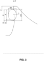
- Figures 2 and 3 show a cross-sectional view of the turbine wheel (10) of the Figure 1 , where the cross-sectional plane ZZ contains the rotation axis (11).
- the turbine wheel (10) with hub (12) can be seen, which can be rotated around the rotation axis (11).
- At the front of the hub (12) is a fluid flow region (14) of the turbine wheel (10), whereby the turbine blades mounted on the hub (12) in the fluid flow region (14) are not shown.
- the cross-sectional contour of the mass removal indentation (13) and the cross-sectional contour of a marking bead (16) can be seen in the hub rear wall (15).
- FIG 3 the geometric dimensions and relationships of parts of the hub rear wall (15) and in particular of the mass removal indentation (13) provided therein are visible.
- the mass removal indentation (13) is designed in cross-section as an ellipse segment of an ellipse, where H represents the major semi-axis of the ellipse and B the minor semi-axis of the ellipse.
- the penetration depth C of the mass removal indentation (13) represents the depth of penetration of the ellipse into the hub rear wall (15).
- C is more precisely defined as the deepest penetration depth compared to the contour of the hub rear wall (15) without the mass removal indentation (13).
- all positional information concerning the marking bead (16) refers to the apex of the marking bead (16).
- the marking bead apex diameter G is thus defined, for example, as the diameter of the apex of the marking bead (16).
- the marking bead (16) - or more precisely its apex - is Mass removal indentation (13) radially spaced, where D indicates the radial distance between the apex of the marking bead (16) and the adjacent (here: radially inner) boundary of the mass removal indentation (13).
- the radial distance between the apex of the marking bead (16) and the distant (here: radially outer) boundary of the mass removal indentation (13) is marked with E.
- the mass removal indentation (13) has a radial extent, from the radially inner to the radially outer boundary, of A.
- the ellipsoidally shaped mass removal indentation (13) is defined by an ellipse, where the ellipse has a major semiaxis H and a minor semiaxis B.
- the penetration depth of the mass removal indentation (13) is marked with C.
- F indicates the diameter of the rear wall of the turbine wheel (10) of an exhaust gas turbine.
- Figure 4 shows a detailed view of Figure 2 and Figure 3 and contains an enlarged view of the marking bead (16) and the adjacent (radially inner) boundary of the mass removal indentation (13), with a distance D therebetween.
- the radii of curvature K, L, M define the marking bead (16) geometrically.
- K indicates the concave radius of curvature of the transition between the apex of the marking bead (16) and the radially inner boundary of the mass removal indentation (13), L the convex radius of curvature at the apex of the marking bead (16), and M the concave radius of curvature of the transition from the apex of the marking bead (16) to the region of the hub rear wall (15) which lies radially inside the marking bead (16).
- the marking bead (16) is formed as a convex elevation in and with respect to the hub rear wall (15), the marking bead (16) being geometrically defined by the radii of curvature K, L and M.
- Figure 5 illustrates a method for balancing a turbine wheel (10) for an exhaust gas turbine or an exhaust gas turbine.
- the starting point of the method is the turbine wheel (10) of the Figures 1 to 4 , but still without mass removal indentation (13).
- the unbalance is first determined in a known manner, for example by measuring the unbalance on the rotating turbine wheel (10).
- a material removal profile is determined for the mass removal indentation (13).
- This material removal profile specifies how the material removal should be performed and can be parameterized, for example, by the angular extent (starting and ending angles) and the penetration depth of a mass removal indentation (13) to be created.
- the material removal profile and the resulting mass removal indentation (13) are asymmetrical with respect to the rotation axis (11) to enable unbalance compensation.
- the mass removal indentation (13) is removed by means of a Figure 5
- the ellipsoidal cutting tool (20) shown is introduced into the hub rear wall according to the material removal profile.
- the introduction of mass removal at mass removal positions occurs through a relative movement of the tool (20) and the hub rear wall (15) to one another, for example, through movement of the tool (20) relative to a stationary hub rear wall (15).
- the shape and movement of the ellipsoidal cutting tool (20) determine the shape of the mass removal recess (13).
- the movement of the tool (20) and, resulting from this, the position of the mass removal indentation (13) is aligned relative to the marking bead (16), namely next to and along the marking bead (16), whereby the marking bead (16) is left in place.
- the marking bead (16) thus enables precise orientation for the introduction of the mass removal indentation (13) at a defined location in the hub back wall (15). This ensures during the process that the radially inner region of the hub back wall (15) (radially within the marking bead (16)), which is subject to high mechanical loads or has mechanical stress maxima, is not impaired. Furthermore, a visual inspection after balancing is possible.
- Balancing in the area radially smaller than the marking bead (16) could lead to mechanical limitations with regard to low -cycle fatigue of the turbine wheel (10).
- the radial distance of the tool (20) from the marking bead (16) is not changed during the movement.
- a grinding device with an ellipsoidal grinding head is schematically depicted here as an ellipsoidal cutting tool (20).
- the ellipsoidal grinding head rotates, for example, around a radial axis. Another, approximately inclined, rotation axis is also possible in alternative embodiments.
- the rotation axis is freely variable.
- the method may optionally comprise at least one further determination of the (remaining) unbalance and adjustment or supplementation of the mass removal indentation (13) according to the steps described above.
- the turbine wheel (10) of the exhaust gas turbine is rotatably mounted and rotates about its axis of rotation (11).
- the turbine wheel (10) has a hub (12) and a plurality of turbine blades fastened to the hub (12) and arranged in a fluid flow region (14).
- the fluid flow region (14) is the region in which the fluid, in particular exhaust gas, flows against the turbine blades and performs work in the process.
- the hub (12) has a hub rear wall (15) facing away from the fluid flow region (14). The hub rear wall (15) is therefore arranged on a side of the hub (12) facing away from the fluid flow region (14), approximately opposite it.
- the hub rear wall (15) may also be wetted by the fluid.
- the hub rear wall (15) is preferably free of turbine blades and/or may be arranged in a preferably radial direction (e.g., with an angular deviation of a maximum of 40° relative to the radial plane).
- the hub rear wall (15) has a marking bead (16) running concentrically around the rotation axis (11).
- mass removal takes place at mass removal positions next to the marking bead (16) in the hub rear wall (15) of a turbine wheel (10) of an exhaust gas turbine by means of an ellipsoidal cutting tool.
- the introduction of mass removal at mass removal positions occurs through a relative movement of an ellipsoidal cutting tool and the hub rear wall (15).
- the ellipsoidal cutting tool can be moved and the hub rear wall (15) can remain at rest, the hub rear wall (15) can be moved and the ellipsoidal cutting tool can remain at rest, and a simultaneous movement of the ellipsoidal cutting tool and the hub rear wall (15), as well as all combinations thereof, can occur.
- the ellipsoidal cutting tool is moved at least in the depth direction.
- the marking bead (16) is particularly advantageous when the ellipsoidal cutting tool is a freely movable tool and is held and guided, for example, by a human hand.
- the (relative) movement of the cutting tool is aligned with the marking bead (16) formed in the hub back wall (15) of the turbine wheel (10).
- the introduction of mass removals at mass removal positions in the hub rear wall (15) for balancing a turbine wheel (10) of an exhaust gas turbine is carried out by removing a mass removal indentation (13) that is asymmetrical with respect to the rotation axis (11) using the ellipsoidal cutting tool.
- the position(s) of the mass removal indentation(s) (13) is/are aligned relative to the marking bead (16), with the marking bead (16) being left standing.
- the ellipsoidal cutting tool has a tool machining geometry in the form of an ellipsoid.
- the tool thus has an ellipsoidally shaped cutting tool head for removing material from an ellipsoid segment from the hub rear wall.
- the ellipsoid describing the tool machining geometry is defined by the three semi-axes H, B, and Y.
- H and B correspond to the Figure 3 shown semi-axes of the resulting cross-sectional contour of the mass removal indentation (13)
- Y is the axis perpendicular to these two semi-axes (and thus to the plane of the drawing of the Figure 5 ) perpendicular semi-axis of the ellipsoid describing the tool machining geometry.
- the ellipsoid describing the tool machining geometry has a configuration in which at least two of the three semi-axes H, B, and Y have the same longitudinal extent. In a further embodiment of the ellipsoidal cutting tool, the ellipsoid describing the tool machining geometry has a configuration in which all three semi-axes H, B, and Y have the same longitudinal extent.
- the tool can have a rotating tool head with an elliptical shape corresponding to the tool machining geometry. If the tool head rotates, the axis of rotation is preferably one of the semi-axes, and at least the other two semi-axes are the same.
- the resulting tool machining geometry is a sphere, i.e., it is a spherical cutting tool (e.g., a tool with a ball head).
- a spherical cutting tool has the advantage that the angular orientation of the tool relative to the hub back wall is irrelevant, at least within a certain angular range, which facilitates handling of the tool—especially when the tool is freely movable.
- the ellipsoidal cutting tool can be any tool capable of cutting. Typically, but not limited to, turning tools, drilling tools, countersinking tools, reaming tools, milling tools, planing tools, slotting tools, broaching tools, sawing tools, filing tools, rasping tools, brushing tools, scraping tools, chiseling tools, grinding tools (with and without rotating tools), belt grinding tools, honing tools, lapping tools or sliding chip tools.
- the ellipsoidal cutting tool is a grinding tool with an ellipsoidal grinding head, for example a ball grinding tool with a ball grinding head.
- the mass removal indentation (13) is introduced into the hub rear wall (15) of a turbine wheel of an exhaust gas turbine by an ellipsoidal cutting tool.
- the introduction takes place along a circular sector of the hub rear wall (15) and in the circumferential direction along a circular arc around the axis (11).
- the introduction takes place within a ring segment or circular segment along a circular arc.
- introduction can also take place along any one-dimensional profile on the hub rear wall (15) of a turbine wheel (10).
- the mass removal indentation (13) may be provided as a continuous circular segment, as in Figure 1 shown by way of example. More generally, the mass removal indentation (13) can be provided as a continuous, segmented, interrupted, or discretely punctuated indentation along a circular arc.
- the circular arc, along which the relative movement of the ellipsoidal cutting tool and the hub rear wall (15) occurs, is aligned with the marking bead (16) in the hub rear wall (15) such that the circular arc runs adjacent to the marking bead (16) in the hub rear wall (15).
- the method first comprises determining an imbalance of the turbine wheel (10). Depending on the determined imbalance of the turbine wheel (10), a material removal profile for the mass removal indentation (13) is then generated.
- This material removal profile can be, for example, a one-dimensional profile along a circular segment of the hub rear wall (15) and run along a circular arc next to the marking bead (16) in the hub rear wall (15).
- the material removal profile indicates how the Material removal is to be carried out. Possible embodiments include a continuous, segmented, interrupted, and/or discrete, point-like material removal profile. Any profiles with a (continuous or discrete) angle-dependent penetration depth can be used.
- the profile is limited by a maximum angular range and/or a maximum penetration depth.
- the introduction of a material removal profile for the mass removal indentation (13) can also take place without prior determination of an imbalance of the turbine wheel (10).
- the material removal profile can, for example, comprise a (angular) center position on the hub rear wall (15), an angular range along the circular arc, a longitudinal extension along the circular arc of the mass removal indentation (13), and/or the (constant or angle-dependent) material removal depth C.
- a material removal depth C that can be varied over the respective angular range can be specified for the mass removal indentation (13), thus creating, for example, runouts.
- one material removal profile can also be provided for several mass removal indentations (13).
- the mass removal indentation (13) is introduced into the hub rear wall (15) of a turbine wheel of an exhaust gas turbine. According to one aspect, the introduction of the mass removal indentation (13) reduces the imbalance of the turbine wheel.
- a removal-free hub test geometry is defined.
- This removal-free hub test geometry represents a configuration of the hub (12), in particular of the hub rear wall (15), without any material removal in the hub rear wall (15).
- a maximum removed hub test geometry is defined (for example as a further hub test geometry) as the hub test geometry with the maximum permissible material removal in the hub rear wall (15).
- the maximum permissible material removal in the hub rear wall (15) is specified, for example based on conditions such as typically required removal, minimum permissible hub residual wall thickness at the positions of the material removal, manufacturing processes and manufacturing possibilities at the positions of the Material removal and/or structural mechanical requirements at the positions of the material removal,
- a first hub quality parameter is calculated based on the maximum removed hub test geometry, i.e., taking into account the maximum permissible material removal in the hub rear wall (15).
- the hub geometry is optimized by optimizing a hub optimization variable determined using the first hub quality parameter.
- a second hub quality parameter can also be calculated based on the removal-free hub test geometry, i.e., without taking into account the maximum permissible material removal in the hub rear wall (15).
- the hub optimization variable is then also determined using the second hub quality parameter, for example, by summing the respective summands determined using the first or second hub quality parameter.
- the (first or second) hub quality parameter can, for example, contain at least one parameter selected from the following list: mechanical stress, mechanical principal stress, mechanical normal stress, mechanical shear stress, a mechanical cycle optimization variable, in particular a cycle fatigue specification (e.g., the simulated cycle capability with respect to fatigue at low cycles), a notch coefficient, a shape coefficient, a support coefficient, a force flow, a geometric configuration of the mass removal indentation (13), and a deviation from a predetermined target total removal.
- the hub optimization variable can, for example, contain a norm (e.g., L2 norm, i.e., square) of such a parameter, or the optionally weighted sum of such norms for several parameters. In particular, the hub optimization variable can thus penalize an increase in the simulated cycle capability with respect to fatigue at low cycles for the wear-free and/or the maximum wear-resistant hub test geometry.
- the optimization is preferably performed iteratively.
- Parameters defining the hub test geometry are preferably changed iteratively to achieve an optimum for the hub optimization size.
- the shape of the maximum permissible material removal can also be optimized by iteratively changing parameters that define the maximum permissible material removal.
- the hub optimization variable can also contain a term that ensures a sufficiently large maximum permissible material removal, such as a term that penalizes a deviation from a specified target total removal.
- the optimization of the hub back wall geometry is carried out using at least one parameter called hub quality parameter.
- the hub geometry is preferably optimized as a multifactorial optimization in which more than one hub quality parameter is used.
- the hub geometry is preferably optimized by optimizing a hub optimization variable determined using several hub quality parameters.
- the optimization is preferably carried out iteratively.
- the material removals subtracted from the hub test geometry are preferably changed iteratively and consequently several hub quality parameters are calculated and compared with the already existing similar hub quality parameters.
- the comparison of the hub quality parameters and the optimization can be carried out using any type of mathematical optimization procedure that is suitable for this purpose.
- the iterative change of the material removals subtracted from the hub test geometry is limited by a hub test geometry without any material removals and by a hub test geometry with maximum permissible material removals.
- the turbine wheel (10) is rotatably mounted and rotates about its axis of rotation (11).
- the turbine wheel (10) has a hub (12) and a plurality of turbine blades fastened to the hub (12) and arranged in a fluid flow region (14).
- the hub (12) has a hub rear wall (15) facing away from the fluid flow region (14).
- a mass removal indentation (13) which is asymmetrical with respect to the axis of rotation (11) for balancing the turbine wheel (10).
- the mass removal indentation (13) is designed as a concave depression in the hub rear wall (15) with a cross-sectional contour of the Mass removal indentation (13) designed in the shape of an ellipse segment.
- the cross-sectional contour of the mass removal indentation (13) is defined in a cross-sectional plane ZZ containing the rotation axis (11).
- the hub rear wall (15) has a marking bead (16) running concentrically around the rotation axis (11), wherein the marking bead (16) and the mass removal indentation (13) are adjacent to one another without radially overlapping.
- the mass removal indentation (13) does not overlap the apex of the marking bead (16), and the apex therefore extends continuously in the circumferential direction of the hub rear wall.
- the mass removal indentation (13) has a cross-sectional contour in a cross-sectional plane Z-Z containing the rotation axis (11).
- the cross-sectional contour is ellipsoidal, i.e., represented by an ellipse segment.
- the ellipse describing this ellipse segment is defined by a first (e.g., major) semi-axis H and a second (e.g., minor) semi-axis B of the ellipse.
- the first semi-axis H can extend in the radial direction
- the second semi-axis B of the ellipse can extend in the axial direction.
- the first semi-axis H and the second semi-axis B of the ellipse have the same length, resulting in a cross-sectional contour in the geometric shape of a circular segment in the cross-sectional plane Z-Z containing the rotation axis (11).
- a definition of the cross-sectional contour made herein applies to a plurality of cross-sectional planes Z-Z containing the rotation axis (11) and a portion of the mass removal indentation (13), particularly preferably for each such cross-sectional plane at least in a continuous angular range that covers at least half or even at least 80% of the entire angular range of the mass removal indentation (13).
- a definition made herein preferably applies to all mass removal indentations (13).
- the cross-sectional contour of the mass removal indentation (13) has a minimum radius of curvature Kr min .
- the radius of curvature should typically satisfy a ratio of Kr min / F ⁇ 0.03 and/or Ke min / F ⁇ 0.03, where F indicates the diameter of the turbine wheel (10).
- the result is R / F ⁇ 0.03, where R is the radius of the circular cross-sectional contour. If the lengths of the major semiaxis H and minor semiaxis B are equal, the major semiaxis H and minor semiaxis B correspond to each other, and at the same time the major semiaxis H and minor semiaxis B correspond to the radius R of the circular cross-sectional contour.
- the mass removal indentation (13) has a penetration depth C of C > 0 and/or of C ⁇ 0.6*B, preferably C ⁇ 0.5*B, and particularly preferably C ⁇ 0.4*B, where B is the second (axial and/or small) ellipse semi-axis.
- the mass removal indentation (13) is located in the hub rear wall (15) of the turbine wheel (10) and adjacent to the marking bead (16) also present in the hub rear wall (15).
- the mass removal indentation (13) and/or the marking bead (16) can be introduced at any circumferential and radial position in the hub rear wall (15), with both being located adjacent to one another, i.e., without any further functional surface features in between.
- the mass removal indentation (13) and/or the marking bead (16) are preferably introduced in the radially outer half of the hub rear wall (15) (relative to the diameter F), preferably at least partially in the radially outer third.
- the mass removal indentation (13) is preferably positioned (completely) radially outside the marking bead (16).
- the region of the hub rear wall (15) within the marking bead (16) is free of the mass removal indentation (13) and/or is completely rotationally symmetrical.
- the marking bead (16) makes it possible to mark an area for the mass removal indentation (13) (namely, for example, radially outside the marking bead (16)) and/or to ensure the marking of an area not intended for the mass removal indentation (13) (namely, for example, radially inside the marking bead (16)).
- the marking bead (16) ensures and easily verifies that the mass removal indentation (13) is only placed in the intended area and not outside of this area. This is particularly useful when the Hub back wall geometry was optimized for the mass removal recess (13) provided therein.
- any tool capable of machining can be used to create the mass removal indentation (13).
- any tool capable of machining can be used to create the mass removal indentation (13).
- turning tools, drilling tools, countersinking tools, reaming tools, milling tools, planing tools, shaping tools, broaching tools, sawing tools, filing tools, rasping tools, brushing tools, scraping tools, chiseling tools, grinding tools with and without rotating tools, belt grinding tools, honing tools, lapping tools, or sliding cutting tools may be mentioned.
- the cutting tool is a grinding tool with an ellipsoidal grinding head.
- this grinding tool has a spherical grinding head and is therefore a spherical grinding tool with a spherical grinding head.
- the cutting tool with an ellipsoidal grinding head can also be shaped such that only the part of the cutting tool that is in contact with the turbine wheel (10) during the introduction of mass removal indentations (13) has an ellipsoidal shape.
- the introduction of a mass removal indentation (13) for balancing a turbine wheel (10) of an exhaust gas turbine takes place within a circular sector of the hub rear wall (15) of a turbine wheel (10) of an exhaust gas turbine and in the circumferential direction along a circular arc.
- the introduction takes place within a ring segment or circular segment along a circular arc.
- a continuous, segment-like, interrupted, or discrete point-like introduction along the circular arc is mentioned.
- the hub rear wall (15) of a turbine wheel (10) of an exhaust gas turbine has a marking bead (16), said marking bead (16) being rotationally symmetrical with respect to the rotation axis (11) and extending concentrically around the rotation axis (11).
- the marking bead (16) in the hub rear wall (15) has a cross-sectional contour which is in a plane containing the rotation axis (11) Cross-sectional plane ZZ.
- the cross-sectional contour of the marking bead (16) is convex and raised relative to the hub rear wall (15).
- the marking bead (16) is radially spaced by a distance D from the mass removal indentation (13) also contained in the hub rear wall (15) of a turbine wheel (10) of an exhaust gas turbine.
- E A + D and E ⁇ (F - G) / 2 and G / F > 0.5, where A is the radial extent of the mass removal indentation (13) (radial distance between the radially inner boundary of the mass removal indentation (13) and the radially outer boundary of the mass removal indentation (13)), D is the radial distance between the marking bead (16) and the radially closer (here radially inner) boundary of the mass removal indentation (13), E is the radial extent between the marking bead (16) and the radially further (here radially outer) boundary of the mass removal indentation (13), F is the diameter of the rear wall of a turbine wheel (10) of an exhaust gas turbine and G is the diameter of the marking bead (16), i.
- the radial position of the marking bead is always defined by its apex.
- an individual radial spacing D from the marking bead (16) can be determined and applied for each mass removal indentation (13).
- an identical radial spacing D is selected and applied for all mass removal indentations (13).
- the minimum radial distance D between the mass removal indentation (13) and the marking bead (16) is preferably 0 ⁇ D ⁇ 0.05*F, particularly preferably 0 ⁇ D ⁇ 0.025*F.
- the (preferably rotationally symmetric) cross-sectional contour of the marking bead (16) has a vertex, a radially inner flank opposite the vertex, and a radially outer flank opposite the vertex.
- the radially inner flank has a concave radius of curvature M
- the radially outer flank has a concave radius of curvature K
- the vertex has a convex radius of curvature L. If the radius of curvature is not constant, these variables describe the smallest radius of curvature.
- K indicates the (smallest) radius of curvature of the transition between the vertex of the marking bead (16) and the radially inner boundary of the mass removal indentation (13), L the (smallest) radius of curvature at the vertex of the marking bead (16), and M the (smallest) Radius of curvature of the transition from the apex of the marking bead (16) to the region of the hub rear wall (15) which lies radially within the marking bead (16).
- K > 0, L ⁇ 0 and/or M > 0 applies.
- K / F ⁇ 0.07, M / F ⁇ 0.07, L / K ⁇ 0.15 and/or L / M ⁇ 0.1 preferably apply.
- the surface of the hub rear wall (15) is a reworked surface in the entire radial region at least from the radius of the marking bead (16) to the outermost radius of the mass removal indentation (13), thus having a higher smoothness and precision than, for example, a surface obtained directly by casting.
- the marking bead (16) in the hub rear wall (15) of a turbine wheel (10) of an exhaust gas turbine can be mounted at any radial position.
- the marking bead (16) is located radially within the mass removal recess (13).
- the imbalance of the turbine wheel is lower than the imbalance of a corresponding (imaginary) turbine wheel with a rotationally symmetric hub without a mass removal indentation (13).
- the fatigue cycle capability of the turbine wheel at low cycles is not lower, or at most lower, by 2% than the cycle capability of a corresponding (imaginary) turbine wheel with a rotationally symmetric hub without a mass removal indentation (13).
- a turbine wheel (10) of an exhaust gas turbine relate to exhaust gas turbines of any design, preferably to radial exhaust gas turbines or mixed-flow exhaust gas turbines (also referred to as diagonal exhaust gas turbines).
- the turbine wheel (10) is designed as a radial turbine wheel.
- the turbine wheel (10) is designed as a mixed-flow (diagonal) exhaust gas turbine wheel, i.e., with a hub front wall whose inlet tangent runs in a diagonal direction with both axial and radial components.
- the exhaust turbine is designed to be driven by exhaust gas from an internal combustion engine.
- the exhaust turbine is provided for a turbocharger.
- the exhaust turbine drives a compressor wheel arranged on a common shaft in order to increase the pressure, density, and enthalpy of an intake fluid and thus increase the boost pressure and to generally improve the efficiency of internal combustion engines.
- the exhaust turbine can also drive other energy converters, such as an electric generator and/or a drive shaft.
- an internal combustion engine with the exhaust turbine driven by exhaust gas from the internal combustion engine and a turbocharger with the exhaust turbine are provided.
- an exhaust gas turbine with a turbine wheel (10) which has every feature of the second aspect of the invention.
- the exhaust gas turbine can be operated with any type of exhaust gas.
- all types of exhaust gas turbines such as radial exhaust gas turbines or mixed-flow exhaust gas turbines, are considered.
- the exhaust gas turbine is preferably an exhaust gas turbocharger.
Landscapes
- Engineering & Computer Science (AREA)
- Mechanical Engineering (AREA)
- General Engineering & Computer Science (AREA)
- Physics & Mathematics (AREA)
- General Physics & Mathematics (AREA)
- Supercharger (AREA)
- Turbine Rotor Nozzle Sealing (AREA)
Claims (12)
- Procédé permettant d'équilibrer une roue de turbine (10) destinée à une turbine à gaz d'échappement, dans lequel la roue de turbine (10) peut tourner autour de son axe de rotation (11) et présente un moyeu (12) et une pluralité d'aubes de turbine fixées au moyeu (12) et disposées dans une zone d'écoulement de fluide (14), dans lequel le moyeu présente une paroi arrière de moyeu (15) détournée de la zone d'écoulement de fluide (14) et pourvue d'un bourrelet de marquage (16) s'étendant de manière concentrique autour de l'axe de rotation (11), le procédé comprenant les étapes consistant à :- déplacer un outil ellipsoïde d'enlèvement de copeaux par rapport à la roue de turbine (10) vers une position d'enlèvement de masse à côté du bourrelet de marquage (16) ;- introduire une encoche d'enlèvement de masse (13) asymétrique par rapport à l'axe de rotation (11) dans la paroi arrière de moyeu (15) pour équilibrer la roue de turbine (10) en enlevant, au moyen de l'outil d'enlèvement de copeaux, de la matière de moyeu de la paroi arrière de moyeu (15) à côté du bourrelet de marquage (16) et en réservant le bourrelet de marquage (16).
- Procédé de fabrication d'une roue de turbine (10) pour une turbine à gaz d'échappement selon la revendication 1, dans lequel l'outil d'enlèvement de copeaux est un outil abrasif à tête abrasive ellipsoïde, de préférence un outil de meulage sphérique à tête de meulage sphérique.
- Procédé selon l'une quelconque des revendications précédentes, dans lequel l'encoche d'enlèvement de masse (13) est introduite dans la direction circonférentielle le long d'un segment annulaire autour de l'axe de rotation (11).
- Procédé selon l'une quelconque des revendications précédentes, comprenant en outre les étapes consistant à :- déterminer un déséquilibre de la roue de turbine ;- en fonction du déséquilibre déterminé, régler un profil d'enlèvement de matière pour l'encoche d'enlèvement de masse (13) ; et- introduire l'encoche d'enlèvement de masse (13) avec le profil d'enlèvement de matière.
- Procédé selon l'une quelconque des revendications précédentes, comprenant en outre les étapes consistant à :- définir une géométrie d'essai de moyeu sans enlèvement ; et- calculer un premier paramètre de qualité de moyeu en utilisant une géométrie d'essai à enlèvement maximal comme géométrie d'essai de moyeu sans enlèvement définie moins une quantité d'enlèvement maximale de la paroi arrière de moyeu de la géométrie d'essai de moyeu sans enlèvement ;- de préférence optimiser la géométrie de moyeu par l'optimisation d'une grandeur d'optimisation de moyeu calculée en utilisant le premier paramètre de qualité de moyeu par modification itérative d'une géométrie d'essai de moyeu entre une géométrie d'essai de moyeu sans enlèvement et à enlèvement maximal,dans lequel l'enlèvement de matière de moyeu sur la paroi arrière de moyeu (15) est limité par la quantité d'enlèvement maximale.
- Procédé selon la revendication 5, dans lequel le paramètre de qualité de moyeu comprend au moins un paramètre sélectionné dans la liste suivante : une contrainte mécanique, une grandeur d'optimisation de cycles mécanique, une indication de fatigue de cycle.
- Procédé selon la revendication 5 ou 6, comprenant en outre les étapes consistant à- calculer un deuxième paramètre de qualité de moyeu en utilisant la géométrie d'essai de moyeu définie sans enlèvement de matière de paroi arrière de moyeu de la géométrie d'essai de moyeu ;- de préférence optimiser la géométrie de moyeu par l'optimisation d'une grandeur d'optimisation de moyeu calculée en utilisant les premiers et deuxièmes paramètres de qualité de moyeu par modification itérative d'une géométrie d'essai de moyeu entre une géométrie d'essai de moyeu sans enlèvement et à enlèvement maximal.
- Roue de turbine (10) destinée à une turbine à gaz d'échappement, la roue de turbine (10) pouvant tourner autour de son axe de rotation (11) et présentant :- un moyeu (12) ; et- une pluralité d'aubes de turbine fixées au moyeu (12) et disposées dans une zone d'écoulement de fluide (14), dans laquelle le moyeu (12) présente une paroi arrière de moyeu (15) détournée de la zone d'écoulement de fluide (14), dans laquelleune encoche d'enlèvement de masse (13) asymétrique par rapport à l'axe de rotation (11) se trouve dans la paroi arrière de moyeu (15) pour équilibrer la roue de turbine (10), dans laquelle l'encoche d'enlèvement de masse (13) est réalisée comme un creux concave dans la paroi arrière de moyeu (15) ayant un contour de section transversale sous la forme d'un segment d'ellipse, dans laquelle le contour de section transversale de l'encoche d'enlèvement de masse (13) est défini dans un plan de section transversale (Z-Z) comportant l'axe de rotation (11), dans laquellela paroi arrière de moyeu (15) présente en outre un bourrelet de marquage (16) s'étendant de manière concentrique à l'axe de rotation (11), dans laquelle le bourrelet de marquage (16) et l'encoche d'enlèvement de masse (13) sont voisins l'un de l'autre sans se chevaucher radialement.
- Roue de turbine (10) selon la revendication 8, dans laquelle l'encoche d'enlèvement de masse (13) présente au moins l'une des propriétés suivantes (a) à (g) :(a) le contour de section transversale de l'encoche d'enlèvement de masse (13) présente la forme d'un segment de cercle ;(b) le contour de section transversale de l'encoche d'enlèvement de masse (13) présente un rayon de courbure minimal supérieur à 0,03 * F, F indiquant le diamètre de la paroi arrière de la roue de turbine (10) ;(c) le contour de section transversale de l'encoche d'enlèvement de masse (13) satisfait la condition ((B*B) / H) / F ≥ 0,03, où H indique le demi-grand axe du contour de section transversale elliptique de l'encoche d'enlèvement de masse (13), B indique le demi-petit axe du contour de section transversale elliptique de l'encoche d'enlèvement de masse (13), et F indique le diamètre de la paroi arrière de la roue de turbine (10) ;(d) l'encoche d'enlèvement de masse (13) est disposée au moins en partie dans la moitié radialement extérieure de la paroi arrière de moyeu (15) ;(e) l'encoche d'enlèvement de masse (13) est générée au moyen d'un outil d'enlèvement de copeaux, de préférence au moyen d'un outil abrasif ;(f) l'encoche d'enlèvement de masse (13) s'étend le long d'un segment annulaire s'étendant en circonférence autour de l'axe ;(g) l'encoche d'enlèvement de masse (13) s'étend comme une ligne continue, une série de lignes continues par endroits ou une série d'encoches ponctuelles discrètes.
- Roue de turbine (10) selon la revendication 8 ou 9, dans laquelle le bourrelet de marquage (16) présente au moins l'une des propriétés suivantes (i) à (iv) :(i) le bourrelet de marquage (16) est en relief et convexe dans le plan de section transversale ;(ii) le bourrelet de marquage (16) est à symétrie de révolution par rapport à l'axe de rotation (11) ;(iii) le bourrelet de marquage (16) est disposé selon l'inégalité E ≤ (F - G) / 2 et/ou G / f > 0,5, dans laquelle A indique l'étendue radiale de l'encoche d'enlèvement de masse (13) d'une extrémité radialement intérieure de l'encoche d'enlèvement de masse (13) à une extrémité radialement extérieure de l'encoche d'enlèvement de masse (13), D indique la distance radiale du sommet du bourrelet de marquage (16) par rapport à l'encoche d'enlèvement de masse (13), E = A + D indique la distance radiale du sommet du bourrelet de marquage (16) de la limite radialement extérieure de l'encoche d'enlèvement de masse (13), F indique le diamètre de la roue de turbine (10), et G indique le diamètre du cercle défini par le sommet du bourrelet de marquage (16) ;(iv) le bourrelet de marquage (16) est disposé radialement à l'intérieur de l'encoche d'enlèvement de masse (13).
- Roue de turbine (10) selon l'une quelconque des revendications 8 à 10, dans laquelle la roue de turbine est une roue de turbine radiale pour une turbine à gaz d'échappement radiale ou une roue de turbine à flux mixte pour une turbine à gaz d'échappement à flux mixte.
- Turbine à gaz d'échappement, de préférence turbocompresseur, comprenant une roue de turbine (10) selon l'une quelconque des revendications 8 à 11.
Applications Claiming Priority (2)
| Application Number | Priority Date | Filing Date | Title |
|---|---|---|---|
| EP21174375 | 2021-05-18 | ||
| PCT/EP2022/063443 WO2022243375A1 (fr) | 2021-05-18 | 2022-05-18 | Procédé d'équilibrage de roues de turbines à gaz d'échappement et roue de turbine équilibrée |
Publications (2)
| Publication Number | Publication Date |
|---|---|
| EP4341532A1 EP4341532A1 (fr) | 2024-03-27 |
| EP4341532B1 true EP4341532B1 (fr) | 2025-05-14 |
Family
ID=76325329
Family Applications (1)
| Application Number | Title | Priority Date | Filing Date |
|---|---|---|---|
| EP22729594.6A Active EP4341532B1 (fr) | 2021-05-18 | 2022-05-18 | Procédé d'équilibrage de roues de turbine des turbines à gaz d'échappement, et roue de turbine équilibrée |
Country Status (6)
| Country | Link |
|---|---|
| US (1) | US20250137374A1 (fr) |
| EP (1) | EP4341532B1 (fr) |
| JP (2) | JP7778818B2 (fr) |
| CN (1) | CN117337359A (fr) |
| FI (1) | FI4341532T3 (fr) |
| WO (1) | WO2022243375A1 (fr) |
Family Cites Families (12)
| Publication number | Priority date | Publication date | Assignee | Title |
|---|---|---|---|---|
| JPS56139802U (fr) * | 1980-03-24 | 1981-10-22 | ||
| JP4554189B2 (ja) * | 2003-11-26 | 2010-09-29 | 株式会社エンプラス | 遠心式羽根車 |
| FR2944060B1 (fr) * | 2009-04-06 | 2013-07-19 | Turbomeca | Systeme d'air secondaire pour compresseur centrifuge ou mixte |
| JP5439112B2 (ja) * | 2009-10-07 | 2014-03-12 | 三菱重工業株式会社 | タービン動翼 |
| US8936439B2 (en) * | 2011-07-11 | 2015-01-20 | Hamilton Sundstrand Corporation | Radial turbine backface curvature stress reduction |
| US10087762B2 (en) * | 2011-07-11 | 2018-10-02 | Hamilton Sundstrand Corporation | Scallop curvature for radial turbine wheel |
| IN2015DN00295A (fr) * | 2012-07-02 | 2015-06-12 | Borgwarner Inc | |
| DE102016112521B4 (de) * | 2016-07-07 | 2025-01-02 | Ihi Charging Systems International Germany Gmbh | Laufrad für einen Abgasturbolader, Abgasturbolader und Verfahren zum Auswuchten eines Laufzeugs für einen Abgasturbolader |
| US20190112927A1 (en) * | 2017-10-12 | 2019-04-18 | Borgwarner Inc. | Turbocharger having improved turbine wheel |
| US10669927B2 (en) * | 2017-11-30 | 2020-06-02 | Garrett Transportation I Inc. | Fluid recirculation turbine system |
| US11603762B2 (en) * | 2019-06-11 | 2023-03-14 | Garrett Transportation I Inc. | Turbocharger turbine wheel |
| US11648632B1 (en) * | 2021-11-22 | 2023-05-16 | Garrett Transportation I Inc. | Treatment process for a centrifugal compressor wheel to extend low-cycle fatigue life |
-
2022
- 2022-05-18 US US18/561,183 patent/US20250137374A1/en active Pending
- 2022-05-18 WO PCT/EP2022/063443 patent/WO2022243375A1/fr not_active Ceased
- 2022-05-18 CN CN202280036201.XA patent/CN117337359A/zh active Pending
- 2022-05-18 JP JP2023571551A patent/JP7778818B2/ja active Active
- 2022-05-18 FI FIEP22729594.6T patent/FI4341532T3/fi active
- 2022-05-18 EP EP22729594.6A patent/EP4341532B1/fr active Active
-
2025
- 2025-07-15 JP JP2025118784A patent/JP2025156369A/ja not_active Abandoned
Also Published As
| Publication number | Publication date |
|---|---|
| CN117337359A (zh) | 2024-01-02 |
| FI4341532T3 (fi) | 2025-07-30 |
| JP2025156369A (ja) | 2025-10-14 |
| WO2022243375A1 (fr) | 2022-11-24 |
| KR20240005937A (ko) | 2024-01-12 |
| EP4341532A1 (fr) | 2024-03-27 |
| JP7778818B2 (ja) | 2025-12-02 |
| JP2024518614A (ja) | 2024-05-01 |
| US20250137374A1 (en) | 2025-05-01 |
Similar Documents
| Publication | Publication Date | Title |
|---|---|---|
| EP0972128B1 (fr) | Structure superficielle pour la paroi d'un canal d'ecoulement ou d'une aube de turbine | |
| EP2110193B2 (fr) | Procédé de fraisage d'un disque aubagé monobloc (Blisk) | |
| EP2093012B1 (fr) | Méthode pour l'usinage d'un anneau d'un rotor d'une turbine à gaz avec des aubes integrées | |
| DE69931324T2 (de) | Schrittfräsmethode | |
| DE2627702A1 (de) | Axialstroemungsmaschine | |
| DE102021133772B3 (de) | Verdichterrad | |
| EP3428393B1 (fr) | Roue aubagée d'une turbomachine | |
| DE102014009735A1 (de) | Schaufel und Laufrad einer Strömungsmaschine, sowie Herstellverfahren dafür | |
| WO2012140104A1 (fr) | Dispositif de laminage pour le galetage de renforcement notamment d'éléments aubes d'une partie de rotor d'un réacteur | |
| WO2018007000A1 (fr) | Roue à aubes d'un turbocompresseur à gaz d'échappement, turbocompresseur à gaz d'échappement et procédé d'équilibrage d'un ensemble tournant pour un turbocompresseur à gaz d'échappement | |
| DE102009033618A1 (de) | Verfahren zur Frequenzverstimmung eines Rotorkörpers einer Gasturbine und ein Rotor einer Gasturbine | |
| WO2010046353A1 (fr) | Procédé de fabrication de roues fermées | |
| EP2805017B1 (fr) | Stator pour une turbomachine axiale et procédé de dimensionnement du stator | |
| EP3650709A1 (fr) | Dispositif diffuseur à aubes pour un compresseur radial | |
| DE112016005645T5 (de) | Dichtungsrippe, Dichtungsstruktur, Turbomaschine und Verfahren zum Herstellen einer Dichtungsrippe | |
| DE102016201452A1 (de) | Gasturbinenbrennkammer mit Wandkonturierung | |
| DE102017204243A1 (de) | Dichtfin mit zumindest einer gewölbten Seitenflanke | |
| WO2019072408A1 (fr) | Rotor d'un turbocompresseur à gaz d'échappement, turbocompresseur à gaz d'échappement et procédé d'équilibrage d'un ensemble tournant pour un turbocompresseur à gaz d'échappement | |
| WO2016074889A1 (fr) | Rotor d'une turbomachine à énergie fluidique radiale, étage | |
| EP1705339B1 (fr) | Arbre de rotor, particulièrement pour une turbine à gaz | |
| WO2022243375A1 (fr) | Procédé d'équilibrage de roues de turbines à gaz d'échappement et roue de turbine équilibrée | |
| EP1798376B1 (fr) | Méthode pour la fabrication d'un canal pour un flux secondaire | |
| WO2012019584A1 (fr) | Procédé pour créer une conception d'un élément et procédé pour fabriquer ce dernier | |
| WO2016066511A1 (fr) | Aube mobile de turbine | |
| EP1584791A1 (fr) | Turbomachine et rotor pour turbomachine |
Legal Events
| Date | Code | Title | Description |
|---|---|---|---|
| STAA | Information on the status of an ep patent application or granted ep patent |
Free format text: STATUS: UNKNOWN |
|
| STAA | Information on the status of an ep patent application or granted ep patent |
Free format text: STATUS: THE INTERNATIONAL PUBLICATION HAS BEEN MADE |
|
| PUAI | Public reference made under article 153(3) epc to a published international application that has entered the european phase |
Free format text: ORIGINAL CODE: 0009012 |
|
| STAA | Information on the status of an ep patent application or granted ep patent |
Free format text: STATUS: REQUEST FOR EXAMINATION WAS MADE |
|
| 17P | Request for examination filed |
Effective date: 20231110 |
|
| AK | Designated contracting states |
Kind code of ref document: A1 Designated state(s): AL AT BE BG CH CY CZ DE DK EE ES FI FR GB GR HR HU IE IS IT LI LT LU LV MC MK MT NL NO PL PT RO RS SE SI SK SM TR |
|
| DAV | Request for validation of the european patent (deleted) | ||
| DAX | Request for extension of the european patent (deleted) | ||
| RAP3 | Party data changed (applicant data changed or rights of an application transferred) |
Owner name: ACCELLERON SWITZERLAND LTD. |
|
| GRAP | Despatch of communication of intention to grant a patent |
Free format text: ORIGINAL CODE: EPIDOSNIGR1 |
|
| STAA | Information on the status of an ep patent application or granted ep patent |
Free format text: STATUS: GRANT OF PATENT IS INTENDED |
|
| INTG | Intention to grant announced |
Effective date: 20250114 |
|
| GRAS | Grant fee paid |
Free format text: ORIGINAL CODE: EPIDOSNIGR3 |
|
| GRAA | (expected) grant |
Free format text: ORIGINAL CODE: 0009210 |
|
| STAA | Information on the status of an ep patent application or granted ep patent |
Free format text: STATUS: THE PATENT HAS BEEN GRANTED |
|
| AK | Designated contracting states |
Kind code of ref document: B1 Designated state(s): AL AT BE BG CH CY CZ DE DK EE ES FI FR GB GR HR HU IE IS IT LI LT LU LV MC MK MT NL NO PL PT RO RS SE SI SK SM TR |
|
| REG | Reference to a national code |
Ref country code: GB Ref legal event code: FG4D Free format text: NOT ENGLISH |
|
| REG | Reference to a national code |
Ref country code: CH Ref legal event code: EP |
|
| REG | Reference to a national code |
Ref country code: IE Ref legal event code: FG4D Free format text: LANGUAGE OF EP DOCUMENT: GERMAN |
|
| REG | Reference to a national code |
Ref country code: DE Ref legal event code: R096 Ref document number: 502022003958 Country of ref document: DE |
|
| PGFP | Annual fee paid to national office [announced via postgrant information from national office to epo] |
Ref country code: DE Payment date: 20250521 Year of fee payment: 4 |
|
| PGFP | Annual fee paid to national office [announced via postgrant information from national office to epo] |
Ref country code: CH Payment date: 20250601 Year of fee payment: 4 |
|
| PGFP | Annual fee paid to national office [announced via postgrant information from national office to epo] |
Ref country code: AT Payment date: 20250721 Year of fee payment: 4 |
|
| REG | Reference to a national code |
Ref country code: FI Ref legal event code: FGE |
|
| REG | Reference to a national code |
Ref country code: NL Ref legal event code: MP Effective date: 20250514 |
|
| PG25 | Lapsed in a contracting state [announced via postgrant information from national office to epo] |
Ref country code: ES Free format text: LAPSE BECAUSE OF FAILURE TO SUBMIT A TRANSLATION OF THE DESCRIPTION OR TO PAY THE FEE WITHIN THE PRESCRIBED TIME-LIMIT Effective date: 20250514 Ref country code: PT Free format text: LAPSE BECAUSE OF FAILURE TO SUBMIT A TRANSLATION OF THE DESCRIPTION OR TO PAY THE FEE WITHIN THE PRESCRIBED TIME-LIMIT Effective date: 20250915 |
|
| PGFP | Annual fee paid to national office [announced via postgrant information from national office to epo] |
Ref country code: FI Payment date: 20250725 Year of fee payment: 4 |
|
| REG | Reference to a national code |
Ref country code: LT Ref legal event code: MG9D |
|
| PG25 | Lapsed in a contracting state [announced via postgrant information from national office to epo] |
Ref country code: GR Free format text: LAPSE BECAUSE OF FAILURE TO SUBMIT A TRANSLATION OF THE DESCRIPTION OR TO PAY THE FEE WITHIN THE PRESCRIBED TIME-LIMIT Effective date: 20250815 Ref country code: NO Free format text: LAPSE BECAUSE OF FAILURE TO SUBMIT A TRANSLATION OF THE DESCRIPTION OR TO PAY THE FEE WITHIN THE PRESCRIBED TIME-LIMIT Effective date: 20250814 |
|
| PG25 | Lapsed in a contracting state [announced via postgrant information from national office to epo] |
Ref country code: NL Free format text: LAPSE BECAUSE OF FAILURE TO SUBMIT A TRANSLATION OF THE DESCRIPTION OR TO PAY THE FEE WITHIN THE PRESCRIBED TIME-LIMIT Effective date: 20250514 Ref country code: PL Free format text: LAPSE BECAUSE OF FAILURE TO SUBMIT A TRANSLATION OF THE DESCRIPTION OR TO PAY THE FEE WITHIN THE PRESCRIBED TIME-LIMIT Effective date: 20250514 |
|
| PG25 | Lapsed in a contracting state [announced via postgrant information from national office to epo] |
Ref country code: BG Free format text: LAPSE BECAUSE OF FAILURE TO SUBMIT A TRANSLATION OF THE DESCRIPTION OR TO PAY THE FEE WITHIN THE PRESCRIBED TIME-LIMIT Effective date: 20250514 |
|
| PG25 | Lapsed in a contracting state [announced via postgrant information from national office to epo] |
Ref country code: HR Free format text: LAPSE BECAUSE OF FAILURE TO SUBMIT A TRANSLATION OF THE DESCRIPTION OR TO PAY THE FEE WITHIN THE PRESCRIBED TIME-LIMIT Effective date: 20250514 |
|
| PGFP | Annual fee paid to national office [announced via postgrant information from national office to epo] |
Ref country code: FR Payment date: 20250708 Year of fee payment: 4 |
|
| PG25 | Lapsed in a contracting state [announced via postgrant information from national office to epo] |
Ref country code: RS Free format text: LAPSE BECAUSE OF FAILURE TO SUBMIT A TRANSLATION OF THE DESCRIPTION OR TO PAY THE FEE WITHIN THE PRESCRIBED TIME-LIMIT Effective date: 20250814 |
|
| PGFP | Annual fee paid to national office [announced via postgrant information from national office to epo] |
Ref country code: CZ Payment date: 20250703 Year of fee payment: 4 |
|
| PG25 | Lapsed in a contracting state [announced via postgrant information from national office to epo] |
Ref country code: IS Free format text: LAPSE BECAUSE OF FAILURE TO SUBMIT A TRANSLATION OF THE DESCRIPTION OR TO PAY THE FEE WITHIN THE PRESCRIBED TIME-LIMIT Effective date: 20250914 |
|
| PG25 | Lapsed in a contracting state [announced via postgrant information from national office to epo] |
Ref country code: LV Free format text: LAPSE BECAUSE OF FAILURE TO SUBMIT A TRANSLATION OF THE DESCRIPTION OR TO PAY THE FEE WITHIN THE PRESCRIBED TIME-LIMIT Effective date: 20250514 |
|
| PG25 | Lapsed in a contracting state [announced via postgrant information from national office to epo] |
Ref country code: DK Free format text: LAPSE BECAUSE OF FAILURE TO SUBMIT A TRANSLATION OF THE DESCRIPTION OR TO PAY THE FEE WITHIN THE PRESCRIBED TIME-LIMIT Effective date: 20250514 Ref country code: SM Free format text: LAPSE BECAUSE OF FAILURE TO SUBMIT A TRANSLATION OF THE DESCRIPTION OR TO PAY THE FEE WITHIN THE PRESCRIBED TIME-LIMIT Effective date: 20250514 |
|
| PG25 | Lapsed in a contracting state [announced via postgrant information from national office to epo] |
Ref country code: LU Free format text: LAPSE BECAUSE OF NON-PAYMENT OF DUE FEES Effective date: 20250518 |
|
| PG25 | Lapsed in a contracting state [announced via postgrant information from national office to epo] |
Ref country code: EE Free format text: LAPSE BECAUSE OF FAILURE TO SUBMIT A TRANSLATION OF THE DESCRIPTION OR TO PAY THE FEE WITHIN THE PRESCRIBED TIME-LIMIT Effective date: 20250514 |
|
| PG25 | Lapsed in a contracting state [announced via postgrant information from national office to epo] |
Ref country code: SK Free format text: LAPSE BECAUSE OF FAILURE TO SUBMIT A TRANSLATION OF THE DESCRIPTION OR TO PAY THE FEE WITHIN THE PRESCRIBED TIME-LIMIT Effective date: 20250514 |
|
| PG25 | Lapsed in a contracting state [announced via postgrant information from national office to epo] |
Ref country code: IT Free format text: LAPSE BECAUSE OF FAILURE TO SUBMIT A TRANSLATION OF THE DESCRIPTION OR TO PAY THE FEE WITHIN THE PRESCRIBED TIME-LIMIT Effective date: 20250514 |
|
| REG | Reference to a national code |
Ref country code: BE Ref legal event code: MM Effective date: 20250531 |
|
| REG | Reference to a national code |
Ref country code: DE Ref legal event code: R097 Ref document number: 502022003958 Country of ref document: DE |
|
| PG25 | Lapsed in a contracting state [announced via postgrant information from national office to epo] |
Ref country code: MC Free format text: LAPSE BECAUSE OF FAILURE TO SUBMIT A TRANSLATION OF THE DESCRIPTION OR TO PAY THE FEE WITHIN THE PRESCRIBED TIME-LIMIT Effective date: 20250514 |
|
| PG25 | Lapsed in a contracting state [announced via postgrant information from national office to epo] |
Ref country code: RO Free format text: LAPSE BECAUSE OF FAILURE TO SUBMIT A TRANSLATION OF THE DESCRIPTION OR TO PAY THE FEE WITHIN THE PRESCRIBED TIME-LIMIT Effective date: 20250514 |
|
| PLBE | No opposition filed within time limit |
Free format text: ORIGINAL CODE: 0009261 |
|
| STAA | Information on the status of an ep patent application or granted ep patent |
Free format text: STATUS: NO OPPOSITION FILED WITHIN TIME LIMIT |
|
| REG | Reference to a national code |
Ref country code: CH Ref legal event code: L10 Free format text: ST27 STATUS EVENT CODE: U-0-0-L10-L00 (AS PROVIDED BY THE NATIONAL OFFICE) Effective date: 20260325 |
|
| PG25 | Lapsed in a contracting state [announced via postgrant information from national office to epo] |
Ref country code: IE Free format text: LAPSE BECAUSE OF NON-PAYMENT OF DUE FEES Effective date: 20250518 |
|
| PG25 | Lapsed in a contracting state [announced via postgrant information from national office to epo] |
Ref country code: BE Free format text: LAPSE BECAUSE OF NON-PAYMENT OF DUE FEES Effective date: 20250531 |
|
| 26N | No opposition filed |
Effective date: 20260217 |