EP2093032B1 - Verfahren und Vorrichtung zur Herstellung von mehrschichtigen Naturkorkstoppern und mehrschichtige Naturkorkstopper - Google Patents
Verfahren und Vorrichtung zur Herstellung von mehrschichtigen Naturkorkstoppern und mehrschichtige Naturkorkstopper Download PDFInfo
- Publication number
- EP2093032B1 EP2093032B1 EP09380025A EP09380025A EP2093032B1 EP 2093032 B1 EP2093032 B1 EP 2093032B1 EP 09380025 A EP09380025 A EP 09380025A EP 09380025 A EP09380025 A EP 09380025A EP 2093032 B1 EP2093032 B1 EP 2093032B1
- Authority
- EP
- European Patent Office
- Prior art keywords
- stopper
- elements
- multilayer
- natural cork
- stopper elements
- Prior art date
- Legal status (The legal status is an assumption and is not a legal conclusion. Google has not performed a legal analysis and makes no representation as to the accuracy of the status listed.)
- Active
Links
- 239000007799 cork Substances 0.000 title claims abstract description 147
- 238000000034 method Methods 0.000 title claims abstract description 54
- 238000004519 manufacturing process Methods 0.000 title claims abstract description 25
- 210000003462 vein Anatomy 0.000 claims description 66
- 239000000853 adhesive Substances 0.000 claims description 38
- 230000001070 adhesive effect Effects 0.000 claims description 38
- 238000007689 inspection Methods 0.000 claims description 36
- 210000001015 abdomen Anatomy 0.000 claims description 31
- 230000007547 defect Effects 0.000 claims description 24
- 238000011156 evaluation Methods 0.000 claims description 12
- 238000012545 processing Methods 0.000 claims description 9
- 230000008569 process Effects 0.000 claims description 6
- 230000004044 response Effects 0.000 claims description 6
- 238000005304 joining Methods 0.000 claims description 5
- 238000005498 polishing Methods 0.000 claims description 5
- 238000003825 pressing Methods 0.000 claims description 3
- 230000008859 change Effects 0.000 claims description 2
- 241000261585 Hadrobregmus pertinax Species 0.000 description 15
- 239000002131 composite material Substances 0.000 description 9
- 238000005520 cutting process Methods 0.000 description 8
- 230000037303 wrinkles Effects 0.000 description 5
- 238000001035 drying Methods 0.000 description 4
- 239000000796 flavoring agent Substances 0.000 description 4
- 235000019634 flavors Nutrition 0.000 description 4
- 238000004891 communication Methods 0.000 description 3
- 240000008289 Quercus suber Species 0.000 description 2
- 235000016977 Quercus suber Nutrition 0.000 description 2
- 230000009471 action Effects 0.000 description 2
- 230000006399 behavior Effects 0.000 description 2
- 238000005202 decontamination Methods 0.000 description 2
- 230000003588 decontaminative effect Effects 0.000 description 2
- 230000002950 deficient Effects 0.000 description 2
- 230000000694 effects Effects 0.000 description 2
- 230000001788 irregular Effects 0.000 description 2
- 206010020649 Hyperkeratosis Diseases 0.000 description 1
- 238000013459 approach Methods 0.000 description 1
- 230000015572 biosynthetic process Effects 0.000 description 1
- 238000009835 boiling Methods 0.000 description 1
- 230000008867 communication pathway Effects 0.000 description 1
- 230000001276 controlling effect Effects 0.000 description 1
- 238000007796 conventional method Methods 0.000 description 1
- 229910001651 emery Inorganic materials 0.000 description 1
- 230000006870 function Effects 0.000 description 1
- 239000011521 glass Substances 0.000 description 1
- 238000010438 heat treatment Methods 0.000 description 1
- 238000012423 maintenance Methods 0.000 description 1
- 230000007246 mechanism Effects 0.000 description 1
- 238000012986 modification Methods 0.000 description 1
- 230000004048 modification Effects 0.000 description 1
- 230000003472 neutralizing effect Effects 0.000 description 1
- 238000004080 punching Methods 0.000 description 1
- 230000001105 regulatory effect Effects 0.000 description 1
- 238000007789 sealing Methods 0.000 description 1
- 238000000926 separation method Methods 0.000 description 1
- 238000007493 shaping process Methods 0.000 description 1
- 238000011179 visual inspection Methods 0.000 description 1
Images


Classifications
-
- B—PERFORMING OPERATIONS; TRANSPORTING
- B27—WORKING OR PRESERVING WOOD OR SIMILAR MATERIAL; NAILING OR STAPLING MACHINES IN GENERAL
- B27J—MECHANICAL WORKING OF CANE, CORK, OR SIMILAR MATERIALS
- B27J5/00—Mechanical working of cork
Definitions
- the present invention relates to a method for manufacturing multilayer natural cork stoppers which comprises forming a plurality of substantially cylindrical natural cork stopper elements and joining at their bases two or more of said stopper elements after having been selected, inspected and positioned according to the result of the inspection to form each stopper.
- the present invention also relates to an apparatus for manufacturing multilayer natural cork stoppers which is able to implement said method, and a multilayer natural cork stopper which can be obtained with the mentioned method and/or apparatus.
- the manufacture of natural cork stoppers comprises first extracting pieces of natural cork from the cork oak trees. As they are extracted from the tree, these pieces of natural cork have an elongated irregular concave shape and they have veins arranged in the longitudinal direction of the pieces, i.e., a direction perpendicular to the radial direction of the tree.
- the mentioned veins have the appearance of lines in the edges of the pieces, but they are actually interstitial "plates" which are the concentric layers or growth "rings" of the cork oak tree bark.
- a back and belly or bulge can be distinguished in each natural cork plate.
- the back is the part adjacent to the outer surface, which, before stripping, is in contact with the air, and located therein there is a woody, hard, dark and fragile area which is called callus.
- the belly or bulge is the part adjacent to the inner surface, which, before stripping, is in contact with the living tissue of the tree.
- the natural cork plate preserves the veins corresponding to the growth layers of the cork, which extend approximately parallel to the surfaces of the belly and the back.
- the separation between the veins progressively increases from the belly to the back. Formed between the belly and the back, in a radial direction to the tree and perpendicular to the veins, there are passages or porosities called lenticels, through which the cork breathes and is oxygenated. Furthermore, natural cork plates can include to a greater or lesser extent defects such as cracks, woodworm holes, molds, etc., which are more likely in the area of the back.
- veins and lenticels of natural cork result in quite variable biological shapes which however are generally arranged in clearly identifiable positions and directions, whereby it will be understood that throughout this description the veins and lenticels are often ideally likened to geometric shapes for the sake of simplicity.
- the flattened cork plates are cut into slices with a suitable thickness using a circular cutting knife and said slices are later perforated on the edge, i.e., in a direction parallel to the veins, with cylindrical cutting gouges with a diameter slightly greater than the end diameter that the finished stopper will have.
- the obtained stoppers thus have the veins arranged in a direction approximately parallel to a longitudinal axis of the stopper.
- corks have porosities and even cracks in the area adjacent to the back which reduce the category of the product.
- the intrinsic nature of cork makes the stoppers have a slightly oval cross section after they have been perforated with cylindrical gouges, the larger dimension of said oval shape being arranged in the direction of the lenticels. This oval shaping is solved by means of a final polishing and finishing operation of the diameter of the stopper.
- the natural cork stoppers thus obtained are the most valued due to their good qualities, for example, for closing bottles of quality wine, since they reasonably and naturally assure insulating the wine from the outside air.
- natural cork stoppers have several drawbacks. Firstly, the cork may transmit unwanted flavors to the wine, whereby the stoppers are usually subjected to a decontamination treatment before said final polishing and finishing operation, but it is difficult to assure that the decontamination reaches the core of the natural cork stopper.
- Another common drawback of natural cork stoppers is that they are very heterogeneous, whereby some of them may have quite variable defects or imperfections causing defective mechanical behaviors that are very difficult to predict and solve even with an individual visual inspection of each stopper. These defective mechanical behaviors include allowing communication pathways between the inside of the bottle and the outer air, which may oxidize the wine and/or cause the wine to leak out.
- a first, and perhaps most problematic, area is in the interface between the stopper and the neck of the bottle at the ends of the veins of the cork where, due to bottling pressure and time, wrinkles or channels are formed parallel to the axis of the stopper. This occurs because the structure and elasticities of the areas with and without veins are very different.
- a second problematic area is also in the interface between the stopper and the glass, but in areas perpendicular to the veins located mainly in the part corresponding to the back of the cork, where there may be cracks, porosities or holes communicating with the outside, making the entrance of air or the leaking of wine possible.
- a third and perhaps less common but more alarming problematic area is the core of the stopper, where there may be holes, passages and other defects making communication between the inside and the outside of the bottle possible.
- Patent EP-A-1393869 proposes solving the drawbacks of natural cork stoppers by providing a multilayer natural cork stopper made up of multiple layers or substantially cylindrical stopper elements adhered at their bases, wherein the cork forming each of said stopper elements has its veins extended between the upper and lower bases of the cylinder, substantially in the axial direction thereof, and wherein the ends of the veins are offset with regard to one another in the interfaces between two contiguous stopper elements. Therefore, the ends of possible passages of the natural cork existing in the stopper elements are offset with regard to one another in said interfaces, preventing communication through the core of the multilayer stopper between the upper and lower bases thereof.
- the mentioned patent EP-A-1393869 also discloses a method for manufacturing the mentioned multilayer stopper which involves forming a composite slice by adhering non-consecutive multiple slices from one and the same plate or from different natural cork plates, with the interfaces between slices substantially perpendicular to the veins of the cork, and subsequently punching the stoppers on the edge of said composite slice in the direction parallel to the veins of the natural cork.
- the multilayer stopper according to the mentioned patent EP-A-1393869 is a good approach, it only provides an offsetting of the veins of the different stopper elements of the multilayer stopper to prevent passages communicating the bases of the multilayer stopper through the core, but it does not take into account other possible variations in the placement of the stopper elements in the multilayer stopper that allow preventing, as much as possible, the presence, for example, of defects, such as cracks, woodworm holes and molds, in the bases of the multilayer stopper, or neutralizing the effect of some intrinsic characteristics of the cork, such as the existence of the belly and the back.
- a composite slice by adhering non-consecutive multiple slices from one and the same plate or from different plates provides a random movement "in parallel" of the veins in the interfaces formed by the mutually joined surfaces of the slices, and this random offsetting "in parallel" of the veins may be suitable, for example, for a multilayer stopper perforated in a specific location of the composite slice, but it may be a drawback for another multilayer stopper perforated in another location of the same composite slice.
- the slices in the composite slice will have their areas corresponding to the belly and to the back of the natural cork plate alternated, but in no case will the stopper elements of the multilayer stoppers perforated from a composite slice have their areas corresponding to the belly and to the back of the natural cork selected and arranged in a controlled way in the manner deemed most suitable.
- the use of a composite slice does not allow having the veins of the slices crossing one another or in relative angular positions different from the substantially parallel position, therefore the different stopper elements of the obtained stoppers will not be arranged in selected relative angular positions.
- FR 1017600 and EP0983834 disclose a multilayer natural cork stopper made up of at least two natural cork stopper elements juxtaposed and joined at therir bases by means of adhesive.
- the stopper elements are obtained by cutting rings, acting perpendicular to a sheet of cork, so that resulting elements are washers or pieces having lenticels that run parallel to the axis of the stopper as shown in Fig 3B of EP0983830 and the veins of the natural cork are perpendicular to that axis providing a sealing effect.
- the internal structure of the agglomerated cork is substantially amorphous and isotropic, and for this reason, the fact the one of the two stopper elements to be joined is made of agglomerated cork makes it unnecessary to take into account the arrangement of the veins and lenticels of the other stopper element, which is made of natural cork and has a rather short length, when forming the multilayer stopper.
- these multilayer stoppers with an agglomerated cork stopper element have a lower quality than the multilayer stoppers made entirely of natural cork and are not considered suitable for closing bottles of quality wine.
- the present invention provides a method for manufacturing multilayer natural cork stoppers, which are made up of several stopper elements, all made of natural cork, juxtaposed and joined at their bases.
- the method of the present invention comprises, firstly, randomly taking a group of two or more of said natural cork stopper elements to be used as components for forming one multilayer stopper, each of said stopper elements having a substantially cylindrical surface around a longitudinal axis and two opposite base surfaces substantially perpendicular to said longitudinal axis.
- the method comprises inspecting at least two of the stopper elements taken, which are envisaged to form ends of said multilayer stopper, said inspection covering areas including at least the two base surfaces of each inspected stopper element.
- the method then comprises designating, according to the result of said inspection and based on a first pre-established selection criterion, relative angular positions of the stopper elements with respect to their longitudinal axes to be occupied in said multilayer stopper.
- the method comprises arranging the stopper elements in said designated relative angular positions, aligning them with respect to their longitudinal axes such that ones of their base surfaces are facing one another, and placing the respective facing base surfaces of the stopper elements to be mutually joined in contact with an intermediating adhesive.
- the stopper elements can be previously obtained by perforating natural cork slices in a direction parallel to veins of the natural cork.
- the stopper elements thus obtained have veins of the natural cork arranged substantially parallel to their longitudinal axes, lenticels of the natural cork arranged substantially perpendicular to said veins, and can furthermore include imperfections and/or defects.
- the mentioned first pre-established selection criterion takes into account the positions and/or the local density of the veins in the base surfaces of each inspected stopper element when designating said relative angular positions for the purpose of providing a discontinuity of the veins in an interface formed by the mutually joined base surfaces of the stopper elements in the multilayer stopper and in a substantially cylindrical surface formed by the aligned cylindrical surfaces of the stopper elements in the multilayer stopper.
- multilayer stoppers made entirely of natural cork can be achieved which virtually ensure that when they are used to close a container, such as a bottle of quality wine, there will be no communication paths between the inner content of the container and the outer air, either through the core of the stopper, since any crack or woodworm hole existing in one of the stopper elements will be interrupted in the interface between this stopper element and the adjacent stopper element, or through the interface between the substantially cylindrical surface of the multilayer stopper and the neck of the container, since the possible wrinkles or channels parallel to the longitudinal axis of the stopper occurring over time by the veins in the substantially cylindrical surface of the different stopper elements will also be interrupted in the interfaces between adjacent stopper elements.
- the multilayer stoppers produced by the method of the present invention are thus significantly more able to prevent the content of the container from being oxidized and/or the content of the container from leaking out in comparison with one-piece natural cork stoppers or with the multilayer stoppers obtained according to the prior art.
- the method of the present invention further comprises the additional step of designating, according to the result of said inspection and based on a second pre-established selection criterion, the one of the two base surfaces of each inspected stopper element to be joined, and arranging the stopper elements with the respective designated base surfaces to be mutually joined facing one another before placing them in contact with the intermediation of said adhesive.
- the mentioned second pre-established selection criterion comprises taking into account the number of the mentioned lenticels, imperfections and/or defects present in the base surfaces of the stopper elements to designate the one of the two base surfaces of each inspected stopper element having a greater number of lenticels, imperfections and/or defects as one of the base surfaces to be joined to form said interface in the multilayer stopper.
- the base surfaces of the finished multilayer will be formed by those base surfaces of the stopper elements which are in better conditions, i.e., having a smaller number of lenticels, imperfections and/or defects. It is known that the lenticels, especially if they are cut lengthwise or on the bias, as well as the cracks, woodworm holes, and other imperfections and defects in the base surface of a natural cork stopper can transmit unwanted flavors to the content of a container closed with this stopper.
- the multilayer stoppers obtained by the method of the present invention are able to close a container, such as a bottle of quality wine, with a lower risk of transmitting unwanted flavors to the content of the container in comparison with one-piece natural cork stoppers or with the multilayer stoppers obtained according to the prior art.
- the stopper elements After the stopper elements have been obtained from the perforation of the natural cork slices, the stopper elements can be sorted by known means according to different qualities. Groups of two or more stopper elements of one and the same quality can then be taken to produce multilayer stoppers of the same quality as the stopper elements taken, or stopper elements of different qualities can be combined to produce multilayer stoppers of intermediate qualities.
- the fact of taking a multilayer stopper obtained by the method of the present invention and joining it to another natural cork stopper element, which can be single- or multilayer, to form a multilayer stopper with a greater number of layers is also contemplated within the scope of the present invention.
- the multilayer stopper and the additional stopper element can be joined by juxtaposing the components in an aligned manner and placing in contact their facing bases with the intervention of an adhesive without previously needing to perform an inspection of the components or a positioning thereof determined from the inspection.
- the method optionally comprises emerying the base surfaces of the stopper elements before inspecting the mentioned areas including the base surfaces in order to have more suitable surfaces for the inspection. It also comprises axially pressing the stopper elements of the multilayer stopper against one another once aligned and placed in contact, and keep them pressed in this position until the adhesive is dried, optionally by means of supplying heat and/or vacuum. Finally, and once the adhesive is dried, the method comprises performing a polishing and finishing operation of the substantially cylindrical surface of the multilayer stopper.
- the method of the present invention allows performing a process for decontaminating the natural cork slices before perforating the stopper elements or a process for decontaminating the natural cork stopper elements once they have been perforated and before the emerying operation, which prevents having to decontaminate the finished multilayer stoppers.
- the operation of inspecting the mentioned areas of the stopper elements can be visually performed, it is preferable to inspect the stopper elements by means of electronic image capturing means in cooperation with an electronic evaluation and control system, and then control stopper element handling operations performed by an automatic apparatus to manufacture a multilayer natural cork stopper from the stopper elements taken initially by means of control signals generated by said electronic evaluation and control system.
- the present invention provides an apparatus for manufacturing multilayer natural cork stoppers made up of several natural cork stopper elements juxtaposed and joined at their bases, each stopper element having a substantially cylindrical surface around a longitudinal axis and two opposite base surfaces substantially perpendicular to said longitudinal axis.
- the apparatus essentially comprises support means, an inspection system, an electronic evaluation and control system including data processing means, and a handling system.
- the mentioned support means are arranged to support at least two of the stopper elements in respective stable positions, and said inspection system is arranged to inspect areas including at least the two base surfaces of at least two stopper elements envisaged to form ends of said multilayer stopper while the stopper elements are in said stable positions.
- the inspection system is able to generate data representative of the inspection and send said data to the electronic evaluation and control system.
- the mentioned data processing means included in the electronic evaluation and control system are enabled to process said data representative of the inspection in combination with other data representative of a first selection criterion stored in a memory for the purpose of designating relative angular positions of the inspected stopper elements with respect to their longitudinal axes to be occupied in said multilayer stopper, and to generate a first control signal representative of said designated angular positions.
- the mentioned handling system is provided with means for arranging the stopper elements in said relative angular positions in response to said first control signal received from said electronic evaluation and control system, and for aligning the stopper elements with respect to their longitudinal axes, and placing the base surfaces of the stopper elements mutually facing one another in contact with the intermediation of an adhesive.
- said memory furthermore has stored therein data representative of a second selection criterion
- the data processing means are furthermore able to process the data representative of the inspection in combination with said data representative of a second selection criterion for the purpose of designating those base surfaces of the inspected stopper elements to be joined, and to generate a second control signal representative of said designated base surfaces.
- the handling system is furthermore provided with means for arranging the stopper elements with the designated base surface of each one facing another base surface of another stopper element in response to said second control signal received from said electronic evaluation and control system before placing them in contact with the intermediation of said adhesive.
- the support means preferably comprise a plurality of supports installed on a conveyor system such that they are moved by said conveyor system along a production line.
- the stopper elements are fed by feed means to said supports, which are arranged in the conveyor system for the purpose of supporting the stopper elements in groups of at least two stopper elements taken randomly by the feed means. All the stopper elements of each group are envisaged to form one of the multilayer stoppers, and the inspection and handling systems are arranged to perform the inspection and handling operations on the stopper elements of each group.
- the present invention provides a multilayer natural cork stopper, of the type made up of at least two natural cork stopper elements juxtaposed and joined at their bases by means of adhesive, each of said stopper elements comprising a substantially cylindrical surface around a longitudinal axis and two opposite base surfaces substantially perpendicular to said longitudinal axis, where ones of said base surfaces of the stopper elements are mutually joined forming at least one interface in the multilayer stopper, each stopper element having veins of the natural cork arranged substantially parallel to the longitudinal axis, lenticels of the natural cork arranged substantially perpendicular to said veins, a part corresponding to the belly of the natural cork and another part corresponding to the back of the natural cork on opposite sides with respect to the longitudinal axis, as well as imperfections and/or defects.
- the multilayer stopper according to the present invention is characterized in that the veins and/or said parts corresponding to the belly and to the back of the stopper elements in the multilayer stopper are in different angular positions with respect to their aligned longitudinal axes, whereby the multilayer stopper has a discontinuity in the positions and local density of the veins and in the positions of the parts corresponding to the belly and to the back of the stopper elements in said interface and in a substantially cylindrical surface of the multilayer stopper formed by said substantially cylindrical surfaces of the stopper elements.
- the multilayer stopper of the invention has the part corresponding to the belly of a stopper element substantially aligned with the part corresponding to the back of another adjacent stopper element, and vice versa. Furthermore, the multilayer stopper of the invention has base surfaces formed by those base surfaces of the stopper elements located at the ends having a smaller number of lenticels, imperfections and/or defects.
- reference number 50 designates a one-piece natural cork stopper according to the prior art, which has a substantially cylindrical surface 50c around a longitudinal axis 5 and base surfaces 50a, 50b perpendicular to said longitudinal axis 5.
- the one-piece natural cork stopper 50 has veins V characteristic of the natural cork arranged in directions substantially parallel to its longitudinal axis 5 and lenticels L characteristic of the natural cork arranged in directions substantially perpendicular to said veins V.
- One of the mentioned base surfaces 50a of the one-piece natural cork stopper 50 depicted in Figure 2 presents a smaller number of lenticels cut lengthwise or on the bias in comparison with the other one of the base surfaces 50b depicted in Figure 3 .
- the natural cork can furthermore have imperfections or defects such as cracks or woodworm holes.
- One of the mentioned base surfaces 50a of the one-piece natural cork stopper 50 depicted in Figure 2 presents one of said cracks G, whereas both base surfaces 50a, 50b respectively depicted in Figures 2 and 3 present ends of a woodworm hole C, which probably belong to one and the same woodworm hole communicating the base surfaces 50a, 50b through the core of the stopper.
- the one-piece natural cork stopper 50 of Figures 1 to 3 has several drawbacks. Firstly, the veins V extend continuously along the entire length of the one-piece natural cork stopper 50, whereby, over time, the veins V can form continuous wrinkles or channels parallel to the longitudinal axis 5 in the substantially cylindrical surface 50c in the interface with the neck of a container closed with said one-piece natural cork stopper 50. Through said continuous wrinkles or channels air can enter inside said container and/or the content of the container can leak out. Secondly, there is a risk of similar air entering or similar leaks will occur through the woodworm hole C communicating the base surfaces 50a, 50b of the one-piece natural cork stopper 50.
- Figure 4 shows a cutting operation for cutting a natural cork plate 41 by means of a rotating blade 42 to produce natural cork slices from which one-piece natural cork stoppers 50 can be perforated according to a method of the prior art.
- the slices are cut with a width equivalent to the length of the one-piece natural cork stoppers 50 which are to be obtained.
- the obtained slices are joined to one another to form a composite slice from which the complete multilayer stoppers are perforated.
- the natural cork plates 41 are cut, for example, by means of the rotating blade 42, to obtain slices 43 of a width equivalent to stopper elements.
- the natural cork slices 41 are perforated separately, for example by means of a cylindrical gouge 44, to produce individual stopper elements 3, 4, which can be subsequently used to form multilayer stoppers 6.
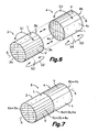
- Figure 6 shows two of the stopper elements 3, 4 obtained, each of which has a substantially cylindrical surface 3c, 4c around a longitudinal axis 5 and two opposite base surfaces 3a, 3b, 4a, 4b, substantially perpendicular to said longitudinal axis 5.
- the natural cork plates 41 have a larger face corresponding to the belly of the natural cork and another opposite larger face corresponding to the back of the natural cork, whereas the veins of the natural cork are arranged substantially parallel to said larger faces and the lenticels substantially perpendicular to the veins.
- the method comprises perforating the slices 43 in a direction parallel to the veins of the natural cork to obtain the stopper elements 3, 4 with veins V of the natural cork arranged substantially parallel to the longitudinal axis 5 and lenticels L of the natural cork arranged substantially perpendicular to said veins V.
- the stopper elements 3, 4 can furthermore include imperfections and/or defects inherent to the natural cork.
- the purpose of the method of the present invention is to manufacture multilayer natural cork stoppers 6 made up of several of the natural cork stopper elements 3, 4, juxtaposed and joined at their bases.
- Figure 7 shows a multilayer stopper 6 made up of two stopper elements 3, 4, which can be obtained by the method of the present invention.
- the method of the present invention allows manufacturing multilayer stoppers made up of a greater number of stopper elements, it is considered that two stopper elements 3, 4 are enough and more than four unnecessary.
- the multilayer stopper 6 of Figure 7 has a substantially cylindrical surface 6c around a longitudinal axis 5, coinciding with the mutually aligned longitudinal axes 5 of the stopper elements 3, 4.
- Said substantially cylindrical surface 6c is formed by the mutually aligned substantially cylindrical surfaces 3c, 4c of the stopper elements 3, 4.
- the multilayer stopper 6 also has opposite base surfaces 6a, 6b, substantially perpendicular to the longitudinal axis 5.
- One of said base surfaces 6a is formed by one of the base surfaces 3a of one of the stopper elements 3 and the other base surface 6b is formed by one of the base surfaces 4b of the other one of the stopper elements 4.
- the multilayer stopper 6 furthermore has an interface 6d formed by the other two base surfaces 3b, 4a of the stopper elements 3, 4 mutually joined by means of an adhesive.
- the method comprises, firstly, randomly taking two or more of the previously obtained natural cork stopper elements 3, 4, such as, for example, the two stopper elements 3, 4 shown in Figure 6 . Areas of the two stopper elements 3, 4 are then inspected, said areas including at least the two mentioned base surfaces 3a, 3b, 4a, 4b thereof. In the event that the stopper elements 3, 4 taken have been more than two, at least those two stopper elements 3, 4 envisaged to form ends of the multilayer stopper 6 will be inspected. It is recommendable to emery the base surfaces 3a, 3b, 4a, 4b of the stopper elements 3, 4 before inspecting the mentioned areas.
- stopper elements 3, 4 will have two of their respective base surfaces 3b, 4a facing one another, as shown in Figure 6 . Finally, the respective facing base surfaces 3b, 4a of the stopper elements 3, 4 will be placed in contact with an intermediating adhesive to be mutually joined and thus obtain the multilayer stopper 6 shown in Figure 7 .
- the method further comprises designating, according to the result of said inspection and a second pre-established selection criterion, the one of the two base surfaces 3a, 3b, 4a, 4b of each inspected stopper element 3, 4 which is considered most suitable to be joined, and accordingly to form the interface 6d of the multilayer stopper 6.
- This allows arranging the stopper elements 3, 4 with the respective designated base surfaces 3a, 3b, 4a, 4b to be joined facing one another before placing them in contact with the intermediation of said adhesive.
- stopper elements 3, 4 In the suitable orientations for the designated base surfaces 3b, 4a to face one another it is necessary to rotate the two stopper elements 3, 4 which will form the end elements of the multilayer stopper 6 with respect to respective axes 53, 54 perpendicular to the corresponding longitudinal axes 5, as is indicated by means of the double arrows G2 in Figure 6 .
- the mentioned first pre-established selection criterion comprises designating said relative angular positions according to the positions and/or the local density of the veins in the base surfaces 3a, 3b, 4a, 4b of each inspected stopper element 3, 4 for the purpose of providing a discontinuity of the veins in the interface 6d of the multilayer stopper 6 and in the substantially cylindrical surface 6c of the multilayer stopper 6.
- the mentioned second pre-established selection criterion comprises designating the one of the two base surfaces 3a, 3b, 4a, 4b of each inspected stopper element 3, 4 having a greater number of lenticels, imperfections and/or defects as one of the base surfaces 3b, 4a to be joined to form said interface 6d in the multilayer stopper 6, which is equivalent to designating the one of the two base surfaces 3a, 3b, 4a, 4b of each inspected stopper element 3, 4 having a smaller number of lenticels, imperfections and/or defects as one of the base surfaces 3a, 4b which will form the base surface 6a, 6b of the multilayer stopper 6.
- the stopper elements 3, 4 are preferably supported by their substantially cylindrical surfaces 3c, 4c.
- the stopper elements 3, 4 of the multilayer stopper 6 are preferably pressed against one another while they are still supported by their substantially cylindrical surfaces in the aligned positions and are kept pressed in this position after their substantially cylindrical surfaces have been released and for a time period provided to allow a drying or curing of the adhesive.
- the method finally comprises performing a final polishing and finishing operation of the substantially cylindrical surface 6c of the multilayer stopper 6 once the adhesive is dried or cured. Any irregularity in the cylindrical shape of the multilayer stopper 6 is thus corrected and any adhesive residue outside the interface 6d is eliminated.
- the stopper elements 3, 4 can be inspected visually. Nevertheless, in a preferred embodiment of the method, the inspection of the areas of the stopper elements 3, 4 is performed by electronic image capturing means in cooperation with an electronic evaluation and control system, which then allows controlling by means of control signals generated by said electronic evaluation and control system an automatic apparatus provided with handling means to perform the remaining steps of the method for the purpose of manufacturing a multilayer natural cork stopper made up of the stopper elements 3, 4.
- an apparatus suitable for implementing the method of the present invention will be described below in reference to Figures 13 to 15 .
- each stopper element 3, 4 has veins V of the natural cork arranged substantially parallel to longitudinal axis 5 and lenticels L of the natural cork arranged substantially perpendicular to said veins V, and it is likewise probable that it includes imperfections and/or defects such as cracks G and/or woodworm holes C.
- each stopper element 3, 4 has a part corresponding to the belly of the natural cork and another part corresponding to the back of the natural cork on opposite sides with respect to longitudinal axis 5, which can be identified from the shapes, positions and local density of the veins V.
- Figures 9 and 10 respectively show the base surfaces 3a, 3b of the stopper element 3, whereas Figures 11 and 12 respectively show the base surfaces 4a, 4b of the stopper element 4 in the same relative angular positions that they occupy in the multilayer stopper 6. It is first seen that in the stopper element 3 ( Figures 9 and 10 ) the veins V are arranged in substantially horizontal directions and the lenticels L are arranged in substantially vertical directions in relation to the drawing, whereas in the stopper element 4 ( Figures 11 and 12 ) the veins V are arranged in substantially vertical directions and the lenticels L are arranged in substantially horizontal directions in relation to the drawing.
- the shapes, positions and local density of the veins V indicate that the stopper element 3 has the part corresponding to the belly of the natural cork on the lower side and the part corresponding to the back of the natural cork on the upper side, whereas the stopper element 4 has the part corresponding to the belly of the natural cork on the left side and the part corresponding to the back of the natural cork on the right side seen in direction XII of Figure 8 ( Figure 12 ).
- both base surfaces 3a, 3b of the stopper element 3 present a similar amount of lenticels L.
- the base surface 3a ( Figure 9 ) of the stopper element 3 has no significant imperfection or defect and for this reason has been selected to form one of the base surfaces 6a of the multilayer stopper 6, whereas the other opposite base surface 3b of the stopper element 3 has a crack G, therefore it has been designated to form part of the interface 6d of the multilayer stopper 6.
- both base surfaces 4a, 4b of the stopper element 4 have openings of a woodworm hole C, which probably indicates the existence of a woodworm hole C communicating the base surfaces 4a, 4b through the core of the stopper element 4.
- the base surface 4a ( Figure 11 ) of the stopper element 4 has a significantly greater number of lenticels L in comparison with the other opposite base surface 4b ( Figure 12 ). Accordingly, the base surface 4a with the greater number of lenticels L has been designated to form part of the interface 6d of the multilayer stopper 6, whereby the base surface 4b with a smaller number of lenticels L forms the other one of the base surfaces 6b of the multilayer stopper 6.
- the veins V and/or said parts corresponding to the belly and to the back of the stopper elements 3, 4 are in different angular positions with respect to their aligned longitudinal axes 5. Therefore, the multilayer stopper 6 has a discontinuity in the positions and local densities of the veins V and a discontinuity in the positions of the parts corresponding to the belly and to the back of the stopper elements 3, 4 both in the interface 6d and in the substantially cylindrical surface 6c thereof.
- the part corresponding to the belly of a stopper element 3, 4 is offset approximately 90° with respect to the part corresponding to the belly of the other adjacent stopper element 3, 4, although any other offset angle is within the scope of the invention.
- the part corresponding to the belly of a stopper element 3, 4 is substantially aligned with the part corresponding to the back of another adjacent stopper element 3, 4, and vice versa, or in other words, the parts corresponding to the belly and to the back of the adjacent stopper elements 3, 4 are offset approximately 180° with respect to one another, in which case it could mistakenly give the impression that the veins V are only offset in parallel when they are actually offset angularly.
- the multilayer stopper has base surfaces 6a, 6b formed by those base surfaces 3a, 4b of the stopper elements 3, 4 located at the ends having a smaller number of lenticels L, imperfections and/or defects.
- the mentioned multilayer stoppers 6 are made up of several natural cork stopper elements 3, 4 juxtaposed and joined at their bases.
- Each stopper element 3, 4 has a substantially cylindrical surface 3c, 4c around a longitudinal axis 5 and two opposite base surfaces 3a, 3b, 4a, 4b substantially perpendicular to said longitudinal axis 5.
- the apparatus of the embodiment shown is prepared to form multilayer stoppers 6 each made up of two stopper elements 3, 4, although a person skilled in the art will be able to easily adapt the apparatus to form multilayer stoppers 6 made up of a greater number of stopper elements.
- the apparatus comprises a conveyor system 21a, 21b arranged to move support means along a production line.
- Said support means include a plurality of supports 26, 27 ( Figures 14 and 15 ) arranged in groups of two, and the supports of each group serve to support two of the stopper elements 3, 4 in respective stable positions.
- the conveyor system shown only schematically in Figure 13 can be formed, for example, by two parallel conveyors, and preferably a first pair of parallel conveyors carrying supports 26 of a first type ( Figure 14 ) to cover a first portion of the production line and a second pair of parallel conveyors carrying supports 27 of a second type ( Figure 15 ) to cover a second portion of the production line, as will be explained below.
- the apparatus also comprises feed means 20a, 20b configured and arranged to feed the stopper elements 3, 4 to the supports 26 of the conveyor system 21a, 21b in said first section of the production line.
- feed means 20a, 20b can comprise, for example, a pair of conventional vibratory hoppers with a helical ramp, which are able to randomly take stopper elements 3, 4 to form the mentioned groups of two stopper elements 3, 4 on the supports 26.
- the two stopper elements 3, 4 of each group are thus determined as the components which will form each multilayer stopper 6.
- the conveyor system 21a, 21 b makes the stopper elements 3, 4 of each group pass through an inspection unit 22a, 22b in which there is arranged an inspection system to inspect areas including the two base surfaces 3a, 3b, 4a, 4b of both stopper elements 3, 4 while the latter are in said stable positions on their corresponding supports 26.
- the inspection system comprises, for example, a light source 28 and at least one image capturing device 29 for each base surface 3a, 3b, 4a, 4b of each inspected stopper element 3, 4.
- the mentioned light source 28 is a laser emitter generating a curtain beam that is stationary in relation to the conveyor system 21a, 21b.
- the laser beam in combination with the image capturing device performs a 3D scan of the corresponding base surface 3a, 3b, 4a, 4b of the stopper element 3, 4 by the relative movement between both.
- the inspection system includes means for generating data representative of the inspection and for sending said data to an electronic evaluation and control system 23.
- the mentioned electronic system 23 includes data processing means able to process the data representative of the inspection received from the inspection unit 22a, 22b in combination with data representative of first and second selection criteria stored in a memory for the purpose of determining relative positions of the two stopper elements 3, 4 deemed to be the most advantageous to be occupied in the multilayer stopper 6.
- the electronic system 23 is able to then generate control signals including first and second control signals to control a handling system arranged to handle the stopper elements 3, 4 of each group for the purpose of placing them in the relative positions determined on the basis of the inspection and of the first and second selection criteria, juxtaposing them, aligning them and joining them with the intervention of an adhesive.
- the mentioned relative positions to be occupied by the stopper elements 3, 4 in said multilayer stopper 6 comprise relative angular positions of the stopper elements 3, 4 with respect to their longitudinal axes 5, which are designated from the processing of the data representative of the inspection in combination with the data representative of the first selection criterion, and relative orientations of the stopper elements 3, 4 with respect to respective middle planes perpendicular to their longitudinal axes 5, which are designated from the processing of the data representative of the inspection in combination with the data representative of the second selection criterion.
- the mentioned handling system of the apparatus is provided with an angular position changing device 30 operated in connection with the electronic control system 23 to arrange the stopper elements 3, 4 in said relative angular positions with respect to their longitudinal axes 5 in response to a first control signal received from said electronic system 23.
- the angular position changing device 30 (best shown in Figure 14 ) comprises a mobile element 31, such as a belt or the like, mounted on pulleys located in stationary positions with respect to the conveyor system 21a,21b and operated by a servomotor 44 in connection with the electronic system 23.
- Each of the supports 26 includes a pair of rollers 39a, 39b on which the substantially cylindrical surface 3c, 4c of the corresponding stopper element 3, 4 rests, and the mobile element 31 is arranged perpendicular to the longitudinal axis 5 of the stopper element 3, 4 and parallel to the direction of travel of the conveyor system 21a, 21b, and at a suitable height to make friction contact with the upper part of the substantially cylindrical surface 3c, 4c of the stopper element 3, 4 arranged on the rollers 39a, 39b of the corresponding support 26 while it is moved by the conveyor system 21a, 21b.
- the stopper element 3, 4 By synchronizing the movement speed of the mobile element 31 such that it is identical to the travel speed of the conveyor system 21a, 21b, the stopper element 3, 4 passes through the angular position changing device 30 without altering its initial angular position. In contrast, by regulating the movement speed of the mobile element 31 such that it is different from the travel speed of the conveyor system 21a, 21b, it is possible to make the stopper element 3, 4 rotate with respect to its longitudinal axis 5 a desired angle. When groups of two stopper elements 3, 4 are handled, it is enough to change the angular position of one of them. When the groups are of more than two stopper elements 3, 4, it is preferable to control the angular positions of at least the stopper elements 3, 4 envisaged to form the end elements of the multilayer stopper 6.
- the handling system furthermore includes an orientation changing device 24a, 24b with means for arranging the stopper elements 3, 4 with the respective previously designated base surfaces 3a, 3b, 4a, 4b mutually facing one another, when the multilayer stopper 6 is formed by two stopper elements 3, 4, or with the previously designated base surfaces of the two stopper elements 3, 4 envisaged to form the end elements of the multilayer stopper 6 facing base surfaces of other intermediate stopper elements 3, 4, when the multilayer stopper 6 is formed by more than two stopper elements 3, 4, in response to a second control signal received from said electronic system 23.
- These means are formed, for example, by a first clamp 32 provided with driving means in connection with the electronic system 23 for each of the stopper elements 3, 4 of each group to be handled.
- Each of the mentioned first clamps 32 comprises a pair of clamp arms 33, 34 arranged to grip the corresponding stopper element 3, 4 at its base surfaces 3a, 3b, 4a, 4b, a vertical movement drive to vertically move the clamp arms 33, 34 for the purpose of lifting the gripped stopper element 3, 4 from the corresponding support 26 and leaving it in the same support 26 again, or preferably in another support 27, and a rotation drive to rotate the clamp arms 33, 34 and the gripped stopper element 3, 4 with respect to an axis perpendicular to its longitudinal axis 5 while the gripped stopper element 3, 4 is lifted.
- the supports 26, 27 are arranged in the conveyor system 21 a, 21b such that the supported stopper elements 3, 4 are aligned with respect to their longitudinal axes 5, whereby the rotation drive of the first clamp 32 performs a 180° rotation only if it is considered necessary.
- One of the clamp arms is a fixed clamp arm 33 and the other one is a mobile clamp arm 34 which can be operated to open and close with respect to the fixed clamp arm 33.
- the clamp 32 is controlled such that the fixed clamp arm 33 always makes contact with the designated base surface 3a, 3b, 4a, 4b of the stopper element 3, 4 to be joined and form part of an interface 6d of the multilayer stopper 6, therefore the stopper elements 3, 4 are deposited in the supports 27 with the designated base surfaces 3a, 3b, 4a, 4b to be joined in controlled positions in the axial direction.
- the fixed clamp arm 33 has an engraved surface which, as a result of the pressure exerted by the first clamp 32, is marked in the corresponding base surface 3a, 3b, 4a, 4b of the stopper element 3, 4 to favor the action of the mentioned adhesive.
- the engraved surface of the fixed clamp arm 33 is optionally heated by heating means, such that the heat is transferred to the natural cork in the base surface 3a, 3b, 4a, 4b of the stopper element 3, 4 to additionally favor the action of the adhesive.
- the first clamps 32 are preferably installed on a mobile support (not shown) operated to move in the direction of travel of the conveyor system 21a, 21b at a speed greater than that of the mentioned first pair of parallel conveyors of the conveyor system 21a, 21b, such that the clamps 32 take the stopper elements 3, 4 from the supports 26 with rollers 39a, 39b ( Figure 14 ) installed in the first pair of parallel conveyors, which cover a first portion of the production line, and deposit them in V-shaped supports 27 ( Figure 15 ) installed in the mentioned second pair of parallel conveyors, which cover a second portion of the production line.
- the V-shaped supports 27 support the stopper elements 3, 4 at their ends, preventing any additional rotation thereof around their longitudinal axes 5 and leaving a central portion of the substantially cylindrical surfaces 3c, 4c of the stopper elements 3, 4 free.
- the handling system comprises a joining device 25a, 25b including several second centering clamps 35, one for each stopper element 3, 4 of the group, operated in connection with the electronic control system 23.
- Each of said second centering clamps 35 comprises clamp arms 36, 37 arranged to grip the corresponding stopper element 3, 4 by its substantially cylindrical surface 3c, 4c, and a vertical movement drive to vertically move the clamp arms 36, 37 for the purpose of lifting the gripped stopper element 3, 4 from the corresponding support 27 maintaining its relative angular position and the relative alignment of its longitudinal axis 5 with respect to the longitudinal axis 5 of another or other adjacent stopper element or elements 3.
- the stopper elements 3, 4 are not previously aligned in the conveyor system, and the second centering clamps 35 are provided with movement drives suitable for performing said alignment after gripping and lifting the stopper elements 3, 4. Nevertheless, although the stopper elements 3, 4 are previously aligned on the conveyor system 21a, 21b, as shown in the embodiment of Figure 13 , the second centering clamps 35 preferably comprise movement drives suitable for correcting and assuring the alignment of the stopper elements 3, 4 with respect to their longitudinal axes 5.
- Each second centering clamp 35 further comprises a radial movement drive, i.e., perpendicular to the direction of the longitudinal axis 5 of the gripped stopper element 3, 4, to pass the base surface 3a, 3b, 4a, 4b to be joined of the gripped stopper element 3, 4 on a corresponding adhesive application member 38, which can comprise, for example, an applicator roller in connection with an adhesive supply source 45.
- a radial movement drive i.e., perpendicular to the direction of the longitudinal axis 5 of the gripped stopper element 3, 4, to pass the base surface 3a, 3b, 4a, 4b to be joined of the gripped stopper element 3, 4 on a corresponding adhesive application member 38, which can comprise, for example, an applicator roller in connection with an adhesive supply source 45.
- the second centering clamps 35 likewise comprise an axial movement drive, i.e., parallel to the direction of the longitudinal axis 5 of the gripped stopper element 3, 4, to place the base surface 3a, 3b, 4a, 4b to be joined of the gripped stopper element 3, 4 in contact with the base surface 3a, 3b, 4a, 4b of another aligned stopper element 3, 4 gripped by another second centering clamp 35 with intermediation of the adhesive.
- the handling system finally comprises a pressure device 46a, 46b comprising a grip 40a, 40b arranged to hold the multilayer stopper 6 thus formed by its base surfaces 6a, 6b and to axially press the stopper elements 3, 4 of the multilayer stopper 6 against one another while the stopper elements 3, 4 are still supported by said second centering clamps 35 maintaining their alignment.
- the movements of the handling system are coordinated by the electronic system 23 such that the second centering clamps 35 release the substantially cylindrical surfaces 3c, 4c of the stopper elements 3, 4 only when the grip 40a, 40b has axially held the multilayer stopper 6 by its base surfaces 6a, 6b.
- the grip 40a, 40b will continue applying pressure and holding the multilayer stopper 6 after it has been released by the second centering clamps 35 until the adhesive has dried. The maintenance of the alignment and the angular positions of the stopper elements 3, 4 in the multilayer stopper 6 are thus assured until the adhesive has dried.
- the grip 40a, 40b comprises, for example, two pressure plates pushed in opposite directions by respective mechanisms based on springs.
- the handling system of the apparatus comprises a plurality of first clamps 32 and a plurality of second centering clamps 35 installed in respective mobile supports arranged to be moved parallel to the direction of travel of the conveyor system 21a, 21b for the purpose of simultaneously handling stopper elements 3, 4 belonging to a plurality of groups of stopper elements 3, 4 conveyed by the conveyor system 21a, 21b.
- the handling system of the apparatus likewise comprises a plurality of said grips 40a, 40b installed in a corresponding mobile support, such as, for example, a chain conveyor, preferably configured and arranged to introduce the multilayer stoppers 6 supported by the grips 40a, 40b in a drying oven where the adhesive is dried by applying heat.
- the drying oven is optionally enabled to apply low pressure, or a relative partial vacuum, at the same time as or alternatively to the application of heat.
- the apparatus of the present invention can be used, for example, to juxtapose and join at their bases finished multilayer stoppers 6 and additional stopper elements, which are single- or multilayer, and/or other finished multilayer stoppers 6 to form multilayer stoppers with a greater number of layers. To do so it would be enough to substitute the stopper elements 3, 4 loaded in at least one of the vibratory hoppers of the feed means 20a, 20b with multilayer stoppers 6 obtained by the method of the present invention and to make the apparatus function by omitting the inspection unit 22a, 22b and the angular position changing device 30 and orientation changing device 24a, 24b.
Landscapes
- Engineering & Computer Science (AREA)
- Mechanical Engineering (AREA)
- Life Sciences & Earth Sciences (AREA)
- Forests & Forestry (AREA)
- Closures For Containers (AREA)
- Laminated Bodies (AREA)
- Footwear And Its Accessory, Manufacturing Method And Apparatuses (AREA)
Claims (15)
- Verfahren zur Herstellung mehrschichtiger Naturkorkstopfen gebildet aus mehreren Naturkorkstopfenelementen (3; 4), welche an ihren Basen mittels Klebstoff nebeneinandergestellt und verbunden sind, wobei jedes der verwendeten genannten Stopfenelemente (3; 4) eine wesentlich zylindrische Oberfläche (3c; 4c) um eine Längsachse (5) und zwei gegenüberliegenden, zur genannten Längsachse (5) wesentlich senkrechten, Basisflächen (3a, 3b; 4a, 4b) aufweist, in dem einige der genannten Basisflächen (3a, 3b; 4a, 4b) der Stopfenelemente (3; 4) untereinander verbunden werden, unter Bildung wenigstens einer Schnittstelle (6d) in dem mehrschichtigen Stopfen (6), wobei jedes der Stopfenelemente (3; 4) wesentlich parallel zur Längsachse (5) angeordnete Naturkorkadern, wesentlich senkrecht zu den genannten Adern angeordnete Lentizellen des Naturkorks, wobei ein Teil der Ausbauchung des Naturkorks entspricht und ein anderes Teil der Rückseite des Naturkorks an gegenüberliegenden Seiten in Bezug auf die Längsachse (5) entspricht, sowie Fehler und/oder Fehlstellen aufweist, welches folgende Schritte umfasst:wahlloses Nehmen von wenigstens zwei der genannten Naturkorkstopfenelemente (3; 4);Überprüfen der Bereiche, die wenigstens die genannten zwei Basisflächen (3a, 3b; 4a, 4b) von wenigstens zwei der genommenen Stopfenelemente (3; 4) beinhalten, welche dazu vorgesehen sind, Endelemente des genannten mehrschichtigen Stopfens (6) zu bilden;Bestimmen, gemäß dem Ergebnis der genannten Überprüfung und einem ersten vorbestimmten Wahlkriterium, relativer in dem genannten mehrschichtigen Stopfen (6) einzunehmende Winkellagen der Stopfenelemente (3; 4) in Bezug auf ihre Längsachsen (5);Anordnen der Stopfenelemente (3; 4) in den genannten relativen Winkellagen und mit Ausrichtung ihrer Längsachsen (5) und;in Verbindung Bringen jeweiliger, untereinander zu verbindende Basisflächen (3a, 3b; 4a, 4b) der Stopfenelemente (3; 4), unter Verwendung eines Klebstoffs, gemäß der genannten jeweiligen relativen Winkellage.
- Verfahren gemäß Anspruch 1, dadurch gekennzeichnet, dass es zusätzlich das Bestimmen, gemäß dem Ergebnis der genannten Überprüfung und einem zweiten vorbestimmten Wahlkriterium, der zu verbindenden Basisfläche der beiden Basisflächen (3a, 3b; 4a, 4b) von jedem überprüften Stopfenelement (3; 4), und das Anordnen der Stopfenelemente (3; 4) mit den jeweiligen, zu verbindenden bestimmten Basisflächen (3a, 3b; 4a, 4b) zueinander gerichtet, bevor diese unter Verwendung eines Klebstoffs in Verbindung gebracht werden, umfasst.
- Verfahren gemäß Anspruch 1 oder 2, dadurch gekennzeichnet, dass es den vorherigen Schritt einer Perforierung von Naturkorkscheiben (43), in einer zu den Naturkorkadern wesentlich parallelen Richtung, umfasst, um Stopfenelemente (3; 4) mit wesentlich parallel zur Längsachse (5) angeordneten Naturkorkadern, wesentlich senkrecht zu den genannten Adern angeordneten Lentizellen des Naturkorks, sowie Fehler und/oder Fehlstellen, zu erhalten, und wobei das genannte erste vorbestimmte Wahlkriterium das Bestimmen der genannten relativen Winkellagen gemäß den Lagen und/oder der lokalen Dichte der Adern in den Basisflächen (3a, 3b; 4a, 4b) von jedem überprüften Stopfenelement (3; 4) umfasst, um eine winkelige Diskontinuität der Adern in einer durch die untereinander verbundenen Basisflächen (3a, 3b; 4a, 4b) der Stopfenelemente (3; 4) in dem mehrschichtigen Stopfen (6) gebildeten Schnittstelle (6d), und in einer wesentlich zylindrischen, durch die zylindrischen Oberflächen (3c, 4c) der Stopfenelemente (3; 4) in dem mehrschichtigen Stopfen (6) gebildeten, Oberfläche (6c), bereitzustellen.
- Verfahren gemäß Anspruch 3, dadurch gekennzeichnet, dass das genannte zweite vorbestimmte Wahlkriterium das Bestimmen derjenigen der beiden Basisflächen (3a, 3b; 4a, 4b) von jedem überprüften Stopfenelement (3; 4) umfasst, welche eine große Anzahl an den genannten Lentizellen, Fehlern und/oder Fehlstellen aufweist, als eine der zu verbindenden Basisflächen (3a, 3b; 4a, 4b), um die genannte Schnittstelle (6d) in dem mehrschichtigen Stopfen (6) zu bilden.
- Verfahren gemäß Anspruch 1 oder 2, dadurch gekennzeichnet, dass es das axiale Drücken der Stopfenelementen (3; 4) des mehrschichtigen Stopfens (6) gegeneinander umfasst, einst diese ausgerichtet, in Verbindung gebracht und verklebt worden sind, und das Halten derselben in dieser Lage gedrückt, bis der Klebstoff trocken oder wesentlich ausgehärtet ist, gefolgt von einem endgültigen Polier- und Schleifenvorgang einer wesentlich zylindrischen Oberfläche (6c) des mehrschichtigen Stopfens (6).
- Verfahren gemäß Anspruch 1 oder 2, dadurch gekennzeichnet, dass es die Ausführung des genannten Schritts der Überprüfung der Bereiche der Stopfenelemente (3; 4), visuell oder mittels elektronischer Bildaufnahmemittel in Zusammenwirkung mit einem elektronischen Auswertungs- und Steuerungssystem (23), umfasst.
- Vorrichtung zur Herstellung mehrschichtiger Naturkorkstopfen gebildet aus mehreren Naturkorkstopfenelementen (3; 4), welche an ihren Basen nebeneinandergestellt und verbunden sind, wobei jedes der Stopfenelemente (3; 4) eine wesentlich zylindrische Oberfläche (3c; 4c) um eine Längsachse (5) und zwei gegenüberliegenden, zur genannten Längsachse (5) wesentlich senkrechten, Basisflächen (3a, 3b; 4a, 4b) aufweist, in dem einige der genannten Basisflächen (3a, 3b; 4a, 4b) der Stopfenelemente (3; 4) untereinander verbunden werden, unter Bildung wenigstens einer Schnittstelle (6d) in dem mehrschichtigen Stopfen (6), wobei jedes der Stopfenelemente (3; 4) wesentlich parallel zur Längsachse (5) angeordnete Naturkorkadern, wesentlich senkrecht zu den genannten Adern angeordnete Lentizellen des Naturkorks, wobei ein Teil der Ausbauchung des Naturkorks entspricht und ein anderes Teil der Rückseite des Naturkorks an gegenüberliegenden Seiten in Bezug auf die Längsachse (5) entspricht, sowie Fehler und/oder Fehlstellen aufweist, welche Folgendes umfasst:Trägermittel zum Tragen von wenigstens zwei der Stopfenelemente (3; 4) in jeweilige stabile Lagen;ein Überprüfungssystem zum Überprüfen der Bereiche, die wenigstens die genannten zwei Basisflächen (3a, 3b; 4a, 4b) von wenigstens zwei Stopfenelemente (3; 4) beinhalten, welche dazu vorgesehen sind, Endelemente des genannten mehrschichtigen Stopfens (6) zu bilden, während sich die Stopfenelemente (3; 4) in den genannten stabilen Lagen befinden, und zum Senden die genannte Überprüfung darstellender Daten an einen elektronischen Auswertungs- und Steuerungssystem (23);in dem genannten elektronischen System (23) beinhaltete Datenverarbeitungsmittel, zum Verarbeiten der genannten die Überprüfung darstellende Daten in Verbindung mit Daten, welche ein erstes Wahlkriterium darstellen und in einem Speicher abgelegt sind, zum Bestimmen relativer in dem genannten mehrschichtigen Stopfen (6) einzunehmende Winkellagen der überprüften Stopfenelemente (3; 4) in Bezug auf ihre Längsachsen (5), und zum Erzeugen eines ersten Steuersignals, welches die genannten bestimmten Winkellagen darstellt;ein Handhabungssystem, welches mit Mitteln zum Anordnen der Stopfenelemente (3; 4) in den genannten relativen Winkellagen, als Antwort auf das genannte von dem genannten elektronischen System (23) empfangene erste Steuersignal, zum Ausrichten der Stopfenelemente (3; 4) in Bezug auf ihre Längsachsen (5), und zum in Verbindung Bringen der zueinander gerichteten Basisflächen (3a, 3b; 4a, 4b) der Stopfenelemente (3; 4) unter Verwendung eines Klebstoffs, versehen ist.
- Vorrichtung gemäß Anspruch 7, dadurch gekennzeichnet, dass in dem genannten Speicher ein zweites Wahlkriterium darstellende Daten abgelegt sind und dass die genannte Datenverarbeitungsmittel zusätzlich die genannten die Überprüfung darstellende Daten in Verbindung mit den genannten ein zweites Wahlkriterium darstellende Daten, verarbeiten können, um die Basisfläche (3a, 3b; 4a, 4b) von jedem zu verbindenden überprüften Stopfenelement (3; 4) zu bestimmen, und zum Erzeugen eines zweiten, die genannten bestimmten Basisflächen (3a, 3b; 4a, 4b) darstellenden Steuersignals, und wobei das genannte Handhabungssystem zusätzlich mit Mitteln versehen ist, um die Stopfenelemente (3; 4) mit der bestimmten Basisfläche (3a, 3b; 4a, 4b) jedes einzelnen einer Basisfläche (3a, 3b; 4a, 4b) eines anderen Stopfenelements (3; 4) gerichtet, als Antwort auf das genannte von dem genannten elektronischen System (23) empfangene zweite Steuersignal, anzuordnen, bevor sie unter Verwendung des genannten Klebstoffs in Verbindung gebracht werden.
- Vorrichtung gemäß Anspruch 7 oder 8, dadurch gekennzeichnet, dass die genannten Trägermittel eine Vielzahl von Trägern (26, 27), welche dazu angeordnet sind, mit einem Transportsystem (21 a, 21 b) bewegt zu werden, und Zuführungsmittel (20a, 20b), welche dazu ausgebildet und angeordnet sind, um Stopfenelemente (3; 4) den genannten Trägern (26, 27) in dem genannten Transportsystem (21a, 21 b) zuzuführen, umfassen, wobei die Träger (26, 27) dazu angeordnet sind, die Stopfenelemente (3; 4) in Gruppen aus wenigstens zwei Stopfenelementen (3; 4) zu tragen, welche wahllos durch die Zuführungsmittel (20a, 20b) genommen werden, um jeden mehrschichtigen Stopfen (6) zu bilden.
- Vorrichtung gemäß Anspruch 9, dadurch gekennzeichnet, dass das genannte Handhabungssystem Folgendes umfasst:wenigstens eine Winkellageänderungseinrichtung (30) mit wenigstens einem beweglichen Teil (31), um die Winkellage von wenigstens einem der Stopfenelemente (3; 4) von jeder Gruppe zu ändern, welche dazu vorgesehen sind, einen der Endelemente des mehrschichtigen Stopfens (6) zu bilden;eine Orientierungsänderungseinrichtung (24a, 24b) mit wenigstens einer ersten Klemme (32) welche dazu angeordnet ist, wenigstens einen der überprüften Stopfenelemente (3; 4) von jeder Gruppe zu greifen unddieses in Bezug auf eine zu seiner Längsachse (5) senkrechten Achse zu drehen; undeine Verbindungseinrichtung (25a, 25b) mit mehreren zweiten Zentrierungsklemmen (35) welche dazu angeordnet sind, die Stopfenelemente (3; 4) von jeder Gruppe an ihrer jeweiligen wesentlich zylindrischen Oberfläche (3c; 4c) einzeln zu greifen, diese in Bezug auf ihre Längsachsen (5) auszurichten, die Stopfenelemente (3; 4) in Zusammenwirkung mit einem entsprechenden Klebstoffanwendungselement (38), um den Klebstoff auf ihre jeweiligen zu verbindenden Basisflächen (3a, 3b; 4a, 4b) anzuwenden, zu tragen, und um die zu verbindenden Basisflächen (3a, 3b; 4a, 4b) unter Verwendung des Klebstoffs in Verbindung zu bringen.
- Vorrichtung gemäß Anspruch 10, dadurch gekennzeichnet, dass das genannte Handhabungssystem eine Druckeinrichtung (46a, 46b) umfasst, mit wenigstens einem Griff (40a, 40b), der dazu angeordnet ist, den mehrschichtigen Stopfen (6) an seinen Basisflächen (6a, 6b) festzuhalten, und die Stopfenelemente (3; 4) des mehrschichtigen Stopfens (6) gegeneinander axial zu drücken, während die Stopfenelemente (3; 4) durch die genannten zweiten Zentrierungsklemmen (35) ausgerichtet gehalten werden, und die Stopfenelemente (3; 4) gegeneinander gedrückt und ausgerichtet zu tragen, nachdem die Stopfenelemente (3; 4) durch die zweiten Zentrierungsklemmen (35) gelöst worden sind und bis der Klebstoff trocken oder ausgehärtet ist.
- Vorrichtung gemäß Anspruch 7, dadurch gekennzeichnet, dass das genannte Überprüfungssystem Beleuchtungsmittel (28) und Bildaufnahmemittel (29) in Verbindung mit dem genannten elektronischen System (23) umfasst, welche dazu angeordnet sind, ein Bild jeder Basisfläche (3a, 3b; 4a, 4b) jedes überprüften Stopfenelements (3; 4) aufzunehmen.
- Mehrschichtiger Naturkorkstopfen, der Art, die aus wenigstens zwei Naturkorkstopfenelementen (3; 4) gebildet ist, welche an ihren Basen mittels Klebstoff nebeneinandergestellt und verbunden sind, wobei jedes der genannten Stopfenelemente (3; 4) eine wesentlich zylindrische Oberfläche (3c; 4c) um eine Längsachse (5) und zwei gegenüberliegenden, zur genannten Längsachse (5) wesentlich senkrechten, Basisflächen (3a, 3b; 4a, 4b) umfasst, in dem einige der genannten Basisflächen (3a, 3b; 4a, 4b) der Stopfenelemente (3; 4) untereinander verbunden werden, unter Bildung wenigstens einer Schnittstelle (6d) in dem mehrschichtigen Stopfen (6), wobei jedes der Stopfenelemente (3; 4) wesentlich parallel zur Längsachse (5) angeordnete Naturkorkadern, wesentlich senkrecht zu den genannten Adern angeordnete Lentizellen des Naturkorks, wobei ein Teil der Ausbauchung des Naturkorks entspricht und ein anderes Teil der Rückseite des Naturkorks an gegenüberliegenden Seiten in Bezug auf die Längsachse (5) entspricht, sowie Fehler und/oder Fehlstellen aufweist, dadurch gekennzeichnet, dass die Adern und/oder die genannten Teile, welche der Ausbauchung und der Rückseite der Stopfenelemente (3; 4) der verschiedenen Elemente des mehrschichtigen Stopfens (6) entsprechen, in verschiedenen Winkellagen in Bezug auf ihre ausgerichteten Längsachsen (5) angeordnet sind, wodurch der mehrschichtige Stopfen (6) eine wesentlich zur Längsachse (5) parallelen Diskontinuität in den Lagen und der lokalen Dichte der Adern, und in den Lagen der Teile, die der Ausbauchung und der Rückseite der Stopfenelemente (3; 4) in Bezug auf die genannte Schnittstelle (6d) entsprechen, und in einer wesentlich zylindrischen Oberfläche (6c) des mehrschichtigen Stopfens (6), welche durch die genannten wesentlich zylindrischen Oberflächen (3c; 4c) der Stopfenelemente (3; 4) gebildet ist, aufweist.
- Mehrschichtiger Stopfen gemäß Anspruch 13, dadurch gekennzeichnet, dass das Teil, das der Ausbauchung eines Stopfenelements (3; 4) entspricht wesentlich mit dem Teil ausgerichtet ist, das der Rückseite eines anderen benachbarten Stopfenelements (3; 4), und umgekehrt, entspricht.
- Mehrschichtiger Stopfen gemäß Anspruch 13 oder 14, dadurch gekennzeichnet, dass der mehrschichtige Stopfen (6) Basisflächen (6a, 6b) aufweist, welche durch diejenigen Basisflächen (3a, 3b; 4a, 4b) der Endstopfenelemente (3; 4) gebildet sind, die eine kleinere Anzahl an den genannten Lentizellen, Fehlern und/oder Fehlstellen aufweisen.
Applications Claiming Priority (1)
| Application Number | Priority Date | Filing Date | Title |
|---|---|---|---|
| ES200800478A ES2302486B1 (es) | 2008-02-21 | 2008-02-21 | Metodo y aparato para fabricacion de tapones multicapa de corcho natural y tapon multicapa de corcho natural. |
Publications (2)
| Publication Number | Publication Date |
|---|---|
| EP2093032A1 EP2093032A1 (de) | 2009-08-26 |
| EP2093032B1 true EP2093032B1 (de) | 2011-04-13 |
Family
ID=39514634
Family Applications (1)
| Application Number | Title | Priority Date | Filing Date |
|---|---|---|---|
| EP09380025A Active EP2093032B1 (de) | 2008-02-21 | 2009-02-18 | Verfahren und Vorrichtung zur Herstellung von mehrschichtigen Naturkorkstoppern und mehrschichtige Naturkorkstopper |
Country Status (4)
| Country | Link |
|---|---|
| EP (1) | EP2093032B1 (de) |
| AT (1) | ATE505308T1 (de) |
| DE (1) | DE602009001015D1 (de) |
| ES (2) | ES2302486B1 (de) |
Families Citing this family (5)
| Publication number | Priority date | Publication date | Assignee | Title |
|---|---|---|---|---|
| IT1395893B1 (it) * | 2009-09-18 | 2012-10-26 | Sugherificio Colla E Fresu S R L | Turacciolo e suo metodo di realizzazione. |
| PT109363B (pt) * | 2016-05-04 | 2021-12-13 | Hugo Ferreira Guimaraes | Dispositivo e processo de aproveitamento de qualidade de rolhas de cortiça |
| PT115526B (pt) * | 2019-05-17 | 2021-02-02 | Pedro Moniz Borba Consultoria E Gestao Unipessoal Lda | Processo de produção de corpos cilíndricos de material de cortiça laminada e o produto final obtido por esse processo. |
| EP3981564B1 (de) | 2020-10-09 | 2026-04-01 | Diam Bouchage | Verfahren zur herstellung zylindrischer körper aus laminiertem kork, und nach diesem verfahren erhaltenes endprodukt |
| ES3060233A1 (es) * | 2025-05-30 | 2026-03-25 | Legivel & Imaginario Lda | Tapón de corcho y método de fabricación |
Family Cites Families (10)
| Publication number | Priority date | Publication date | Assignee | Title |
|---|---|---|---|---|
| FR1017600A (fr) * | 1950-04-12 | 1952-12-12 | Manuf Fr De Bouchons | Bouchon de liège composite et procédé de fabrication |
| US3212649A (en) * | 1960-07-15 | 1965-10-19 | American Mach & Foundry | Machine for performing work |
| EP0650405B1 (de) * | 1992-07-13 | 2000-03-08 | Mordechai Hammer | Tragbare, ausfahrbare und zusammenschiebbare bewegungsvorrichtung |
| ES2077515B1 (es) * | 1993-11-18 | 1998-01-01 | Corcho Y Tecnologia Sl | Procedimiento e instalacion para la fabricacion de tapones de corcho. |
| DE69920839D1 (de) * | 1998-09-03 | 2004-11-11 | Salvatore Mannoni | Verfahren und Vorrichtung zur Herstellung von Verschlusselementen aus Naturkork |
| IT1308301B1 (it) * | 1999-10-11 | 2001-12-10 | O M L O S R L Officina Meccani | Macchina per la composizione di tappi in sughero |
| IT1321304B1 (it) | 2000-06-30 | 2004-01-08 | Enrico Ferrari | Procedimento e dispositivo per la realizzazione di tappi. |
| ITTO20010934A1 (it) | 2001-10-03 | 2003-04-03 | Ferrero Alberto | Macchina per la composizione di tappi incollati. |
| ITTO20020345A1 (it) * | 2002-04-22 | 2003-10-22 | Italco S R L | Macchina per la rettifica di tappi di sughero. |
| ES2274951T3 (es) * | 2002-08-30 | 2007-06-01 | Jose Luis Godoy Varo | Tapon multicapa de corcho natural y procedimiento para su fabricacion. |
-
2008
- 2008-02-21 ES ES200800478A patent/ES2302486B1/es not_active Expired - Fee Related
-
2009
- 2009-02-18 EP EP09380025A patent/EP2093032B1/de active Active
- 2009-02-18 AT AT09380025T patent/ATE505308T1/de not_active IP Right Cessation
- 2009-02-18 ES ES09380025T patent/ES2366404T3/es active Active
- 2009-02-18 DE DE602009001015T patent/DE602009001015D1/de active Active
Also Published As
| Publication number | Publication date |
|---|---|
| ATE505308T1 (de) | 2011-04-15 |
| ES2302486A1 (es) | 2008-07-01 |
| DE602009001015D1 (de) | 2011-05-26 |
| EP2093032A1 (de) | 2009-08-26 |
| ES2302486B1 (es) | 2009-07-27 |
| ES2366404T3 (es) | 2011-10-20 |
Similar Documents
| Publication | Publication Date | Title |
|---|---|---|
| EP2093032B1 (de) | Verfahren und Vorrichtung zur Herstellung von mehrschichtigen Naturkorkstoppern und mehrschichtige Naturkorkstopper | |
| CA2291592A1 (fr) | Procede de decalottage de pieces en verre | |
| EP1105262A1 (de) | Verfahren sowie vorrichtung zum zuschneiden sowie zur automatischen entnahme von zuschnittstapeln aus einem mehrlagig geschichteten lagenblok | |
| JPH03226432A (ja) | 成形品をカプセルに収納するための装置および方法 | |
| CN107399445B (zh) | 一种纱团包膜生产线 | |
| CA3081384A1 (en) | Apparatus and method for fabricating laminated wood products | |
| CN106585461A (zh) | 全自动汽车地毯生产线及生产方法 | |
| EP0267121B1 (de) | Verfahren und Vorrichtung zum Biegen von Glasscheiben mit grosser Kapazität | |
| CN112173545A (zh) | 用于检查杆状产品质量的方法和装置 | |
| KR20150030019A (ko) | 폐골프공의 외피 제거 장치 | |
| EP0983830B1 (de) | Verfahren und Vorrichtung zur Herstellung von Verschlusselementen aus Naturkork | |
| US6085813A (en) | Method for making plywood | |
| JPH03503154A (ja) | 断熱シュートの製造の為の装置 | |
| US9469485B2 (en) | Device for alignment of elongated food products | |
| US20180304491A1 (en) | Method for Beveling Veneers | |
| ITTO20090712A1 (it) | Turacciolo e suo metodo di realizzazione. | |
| KR100456321B1 (ko) | 차단막이 형성된 펄프용기 및 그 제조방법 | |
| JP2012066411A (ja) | 単板の切断装置 | |
| JPH07255447A (ja) | 芋の不用部自動除去方法及び装置 | |
| KR200271040Y1 (ko) | 차단막이 형성된 펄프 용기 | |
| DE10161902B4 (de) | Verfahren und Vorrichtung zum Handhaben von Platten | |
| EP3242173B1 (de) | Vorrichtung und verfahren zur verwendung der qualität von korkstopfen | |
| WO2006060855A1 (en) | Material handling for radial timber sawing | |
| JPH0850102A (ja) | 缶蓋検査装置 | |
| EP1202847A1 (de) | Verfahren und vorrichtung zur herstellung von fassdauben |
Legal Events
| Date | Code | Title | Description |
|---|---|---|---|
| PUAI | Public reference made under article 153(3) epc to a published international application that has entered the european phase |
Free format text: ORIGINAL CODE: 0009012 |
|
| AK | Designated contracting states |
Kind code of ref document: A1 Designated state(s): AT BE BG CH CY CZ DE DK EE ES FI FR GB GR HR HU IE IS IT LI LT LU LV MC MK MT NL NO PL PT RO SE SI SK TR |
|
| AX | Request for extension of the european patent |
Extension state: AL BA RS |
|
| 17P | Request for examination filed |
Effective date: 20091022 |
|
| 17Q | First examination report despatched |
Effective date: 20091116 |
|
| AKX | Designation fees paid |
Designated state(s): AT BE BG CH CY CZ DE DK EE ES FI FR GB GR HR HU IE IS IT LI LT LU LV MC MK MT NL NO PL PT RO SE SI SK TR |
|
| GRAP | Despatch of communication of intention to grant a patent |
Free format text: ORIGINAL CODE: EPIDOSNIGR1 |
|
| GRAS | Grant fee paid |
Free format text: ORIGINAL CODE: EPIDOSNIGR3 |
|
| GRAA | (expected) grant |
Free format text: ORIGINAL CODE: 0009210 |
|
| AK | Designated contracting states |
Kind code of ref document: B1 Designated state(s): AT BE BG CH CY CZ DE DK EE ES FI FR GB GR HR HU IE IS IT LI LT LU LV MC MK MT NL NO PL PT RO SE SI SK TR |
|
| REG | Reference to a national code |
Ref country code: GB Ref legal event code: FG4D |
|
| REG | Reference to a national code |
Ref country code: CH Ref legal event code: EP |
|
| REG | Reference to a national code |
Ref country code: IE Ref legal event code: FG4D |
|
| REF | Corresponds to: |
Ref document number: 602009001015 Country of ref document: DE Date of ref document: 20110526 Kind code of ref document: P |
|
| REG | Reference to a national code |
Ref country code: DE Ref legal event code: R096 Ref document number: 602009001015 Country of ref document: DE Effective date: 20110526 |
|
| REG | Reference to a national code |
Ref country code: NL Ref legal event code: VDEP Effective date: 20110413 |
|
| LTIE | Lt: invalidation of european patent or patent extension |
Effective date: 20110413 |
|
| REG | Reference to a national code |
Ref country code: ES Ref legal event code: FG2A Ref document number: 2366404 Country of ref document: ES Kind code of ref document: T3 Effective date: 20111020 |
|
| PG25 | Lapsed in a contracting state [announced via postgrant information from national office to epo] |
Ref country code: NO Free format text: LAPSE BECAUSE OF FAILURE TO SUBMIT A TRANSLATION OF THE DESCRIPTION OR TO PAY THE FEE WITHIN THE PRESCRIBED TIME-LIMIT Effective date: 20110713 Ref country code: LT Free format text: LAPSE BECAUSE OF FAILURE TO SUBMIT A TRANSLATION OF THE DESCRIPTION OR TO PAY THE FEE WITHIN THE PRESCRIBED TIME-LIMIT Effective date: 20110413 Ref country code: SE Free format text: LAPSE BECAUSE OF FAILURE TO SUBMIT A TRANSLATION OF THE DESCRIPTION OR TO PAY THE FEE WITHIN THE PRESCRIBED TIME-LIMIT Effective date: 20110413 Ref country code: PT Free format text: LAPSE BECAUSE OF FAILURE TO SUBMIT A TRANSLATION OF THE DESCRIPTION OR TO PAY THE FEE WITHIN THE PRESCRIBED TIME-LIMIT Effective date: 20110816 Ref country code: HR Free format text: LAPSE BECAUSE OF FAILURE TO SUBMIT A TRANSLATION OF THE DESCRIPTION OR TO PAY THE FEE WITHIN THE PRESCRIBED TIME-LIMIT Effective date: 20110413 |
|
| PG25 | Lapsed in a contracting state [announced via postgrant information from national office to epo] |
Ref country code: FI Free format text: LAPSE BECAUSE OF FAILURE TO SUBMIT A TRANSLATION OF THE DESCRIPTION OR TO PAY THE FEE WITHIN THE PRESCRIBED TIME-LIMIT Effective date: 20110413 Ref country code: SI Free format text: LAPSE BECAUSE OF FAILURE TO SUBMIT A TRANSLATION OF THE DESCRIPTION OR TO PAY THE FEE WITHIN THE PRESCRIBED TIME-LIMIT Effective date: 20110413 Ref country code: AT Free format text: LAPSE BECAUSE OF FAILURE TO SUBMIT A TRANSLATION OF THE DESCRIPTION OR TO PAY THE FEE WITHIN THE PRESCRIBED TIME-LIMIT Effective date: 20110413 Ref country code: LV Free format text: LAPSE BECAUSE OF FAILURE TO SUBMIT A TRANSLATION OF THE DESCRIPTION OR TO PAY THE FEE WITHIN THE PRESCRIBED TIME-LIMIT Effective date: 20110413 Ref country code: GR Free format text: LAPSE BECAUSE OF FAILURE TO SUBMIT A TRANSLATION OF THE DESCRIPTION OR TO PAY THE FEE WITHIN THE PRESCRIBED TIME-LIMIT Effective date: 20110714 Ref country code: CY Free format text: LAPSE BECAUSE OF FAILURE TO SUBMIT A TRANSLATION OF THE DESCRIPTION OR TO PAY THE FEE WITHIN THE PRESCRIBED TIME-LIMIT Effective date: 20110413 Ref country code: BE Free format text: LAPSE BECAUSE OF FAILURE TO SUBMIT A TRANSLATION OF THE DESCRIPTION OR TO PAY THE FEE WITHIN THE PRESCRIBED TIME-LIMIT Effective date: 20110413 Ref country code: IS Free format text: LAPSE BECAUSE OF FAILURE TO SUBMIT A TRANSLATION OF THE DESCRIPTION OR TO PAY THE FEE WITHIN THE PRESCRIBED TIME-LIMIT Effective date: 20110813 |
|
| PG25 | Lapsed in a contracting state [announced via postgrant information from national office to epo] |
Ref country code: NL Free format text: LAPSE BECAUSE OF FAILURE TO SUBMIT A TRANSLATION OF THE DESCRIPTION OR TO PAY THE FEE WITHIN THE PRESCRIBED TIME-LIMIT Effective date: 20110413 |
|
| PG25 | Lapsed in a contracting state [announced via postgrant information from national office to epo] |
Ref country code: CZ Free format text: LAPSE BECAUSE OF FAILURE TO SUBMIT A TRANSLATION OF THE DESCRIPTION OR TO PAY THE FEE WITHIN THE PRESCRIBED TIME-LIMIT Effective date: 20110413 Ref country code: EE Free format text: LAPSE BECAUSE OF FAILURE TO SUBMIT A TRANSLATION OF THE DESCRIPTION OR TO PAY THE FEE WITHIN THE PRESCRIBED TIME-LIMIT Effective date: 20110413 |
|
| PLBE | No opposition filed within time limit |
Free format text: ORIGINAL CODE: 0009261 |
|
| STAA | Information on the status of an ep patent application or granted ep patent |
Free format text: STATUS: NO OPPOSITION FILED WITHIN TIME LIMIT |
|
| PG25 | Lapsed in a contracting state [announced via postgrant information from national office to epo] |
Ref country code: PL Free format text: LAPSE BECAUSE OF FAILURE TO SUBMIT A TRANSLATION OF THE DESCRIPTION OR TO PAY THE FEE WITHIN THE PRESCRIBED TIME-LIMIT Effective date: 20110413 Ref country code: SK Free format text: LAPSE BECAUSE OF FAILURE TO SUBMIT A TRANSLATION OF THE DESCRIPTION OR TO PAY THE FEE WITHIN THE PRESCRIBED TIME-LIMIT Effective date: 20110413 |
|
| 26N | No opposition filed |
Effective date: 20120116 |
|
| PGFP | Annual fee paid to national office [announced via postgrant information from national office to epo] |
Ref country code: FR Payment date: 20120403 Year of fee payment: 4 |
|
| REG | Reference to a national code |
Ref country code: DE Ref legal event code: R097 Ref document number: 602009001015 Country of ref document: DE Effective date: 20120116 |
|
| PG25 | Lapsed in a contracting state [announced via postgrant information from national office to epo] |
Ref country code: IT Free format text: LAPSE BECAUSE OF FAILURE TO SUBMIT A TRANSLATION OF THE DESCRIPTION OR TO PAY THE FEE WITHIN THE PRESCRIBED TIME-LIMIT Effective date: 20110413 |
|
| PG25 | Lapsed in a contracting state [announced via postgrant information from national office to epo] |
Ref country code: MC Free format text: LAPSE BECAUSE OF NON-PAYMENT OF DUE FEES Effective date: 20120229 |
|
| REG | Reference to a national code |
Ref country code: IE Ref legal event code: MM4A |
|
| REG | Reference to a national code |
Ref country code: DE Ref legal event code: R119 Ref document number: 602009001015 Country of ref document: DE Effective date: 20120901 |
|
| PG25 | Lapsed in a contracting state [announced via postgrant information from national office to epo] |
Ref country code: IE Free format text: LAPSE BECAUSE OF NON-PAYMENT OF DUE FEES Effective date: 20120218 |
|
| PG25 | Lapsed in a contracting state [announced via postgrant information from national office to epo] |
Ref country code: MK Free format text: LAPSE BECAUSE OF FAILURE TO SUBMIT A TRANSLATION OF THE DESCRIPTION OR TO PAY THE FEE WITHIN THE PRESCRIBED TIME-LIMIT Effective date: 20110413 |
|
| PG25 | Lapsed in a contracting state [announced via postgrant information from national office to epo] |
Ref country code: BG Free format text: LAPSE BECAUSE OF FAILURE TO SUBMIT A TRANSLATION OF THE DESCRIPTION OR TO PAY THE FEE WITHIN THE PRESCRIBED TIME-LIMIT Effective date: 20110713 Ref country code: DE Free format text: LAPSE BECAUSE OF NON-PAYMENT OF DUE FEES Effective date: 20120901 |
|
| PGFP | Annual fee paid to national office [announced via postgrant information from national office to epo] |
Ref country code: ES Payment date: 20120326 Year of fee payment: 4 |
|
| PG25 | Lapsed in a contracting state [announced via postgrant information from national office to epo] |
Ref country code: MT Free format text: LAPSE BECAUSE OF FAILURE TO SUBMIT A TRANSLATION OF THE DESCRIPTION OR TO PAY THE FEE WITHIN THE PRESCRIBED TIME-LIMIT Effective date: 20110413 |
|
| REG | Reference to a national code |
Ref country code: CH Ref legal event code: PL |
|
| GBPC | Gb: european patent ceased through non-payment of renewal fee |
Effective date: 20130218 |
|
| PG25 | Lapsed in a contracting state [announced via postgrant information from national office to epo] |
Ref country code: LI Free format text: LAPSE BECAUSE OF NON-PAYMENT OF DUE FEES Effective date: 20130228 Ref country code: CH Free format text: LAPSE BECAUSE OF NON-PAYMENT OF DUE FEES Effective date: 20130228 |
|
| REG | Reference to a national code |
Ref country code: FR Ref legal event code: ST Effective date: 20131031 |
|
| PG25 | Lapsed in a contracting state [announced via postgrant information from national office to epo] |
Ref country code: GB Free format text: LAPSE BECAUSE OF NON-PAYMENT OF DUE FEES Effective date: 20130218 Ref country code: FR Free format text: LAPSE BECAUSE OF NON-PAYMENT OF DUE FEES Effective date: 20130228 |
|
| PG25 | Lapsed in a contracting state [announced via postgrant information from national office to epo] |
Ref country code: TR Free format text: LAPSE BECAUSE OF FAILURE TO SUBMIT A TRANSLATION OF THE DESCRIPTION OR TO PAY THE FEE WITHIN THE PRESCRIBED TIME-LIMIT Effective date: 20110413 |
|
| PG25 | Lapsed in a contracting state [announced via postgrant information from national office to epo] |
Ref country code: LU Free format text: LAPSE BECAUSE OF NON-PAYMENT OF DUE FEES Effective date: 20120218 |
|
| REG | Reference to a national code |
Ref country code: ES Ref legal event code: FD2A Effective date: 20140606 |
|
| PG25 | Lapsed in a contracting state [announced via postgrant information from national office to epo] |
Ref country code: HU Free format text: LAPSE BECAUSE OF FAILURE TO SUBMIT A TRANSLATION OF THE DESCRIPTION OR TO PAY THE FEE WITHIN THE PRESCRIBED TIME-LIMIT Effective date: 20090218 |
|
| PG25 | Lapsed in a contracting state [announced via postgrant information from national office to epo] |
Ref country code: ES Free format text: LAPSE BECAUSE OF NON-PAYMENT OF DUE FEES Effective date: 20130219 |