EP2093060A1 - Dispositif de manipulation d'une presse - Google Patents
Dispositif de manipulation d'une presse Download PDFInfo
- Publication number
- EP2093060A1 EP2093060A1 EP09152907A EP09152907A EP2093060A1 EP 2093060 A1 EP2093060 A1 EP 2093060A1 EP 09152907 A EP09152907 A EP 09152907A EP 09152907 A EP09152907 A EP 09152907A EP 2093060 A1 EP2093060 A1 EP 2093060A1
- Authority
- EP
- European Patent Office
- Prior art keywords
- suction
- handling
- handling device
- suction nozzle
- printing
- Prior art date
- Legal status (The legal status is an assumption and is not a legal conclusion. Google has not performed a legal analysis and makes no representation as to the accuracy of the status listed.)
- Withdrawn
Links
- 238000007639 printing Methods 0.000 title claims description 72
- 238000007667 floating Methods 0.000 claims abstract description 12
- 239000011248 coating agent Substances 0.000 claims description 3
- 238000000576 coating method Methods 0.000 claims description 3
- 210000000056 organ Anatomy 0.000 abstract 1
- 239000011521 glass Substances 0.000 description 6
- 238000004519 manufacturing process Methods 0.000 description 6
- 230000001419 dependent effect Effects 0.000 description 2
- 238000003860 storage Methods 0.000 description 2
- 230000001464 adherent effect Effects 0.000 description 1
- 238000004026 adhesive bonding Methods 0.000 description 1
- 230000004323 axial length Effects 0.000 description 1
- 238000000151 deposition Methods 0.000 description 1
- 238000011161 development Methods 0.000 description 1
- 230000018109 developmental process Effects 0.000 description 1
- 238000006073 displacement reaction Methods 0.000 description 1
- 238000005516 engineering process Methods 0.000 description 1
- 230000001771 impaired effect Effects 0.000 description 1
- 238000000034 method Methods 0.000 description 1
- 230000010355 oscillation Effects 0.000 description 1
- 230000002035 prolonged effect Effects 0.000 description 1
- 238000005096 rolling process Methods 0.000 description 1
- 238000005476 soldering Methods 0.000 description 1
- 230000003068 static effect Effects 0.000 description 1
- 238000005406 washing Methods 0.000 description 1
- 238000003466 welding Methods 0.000 description 1
Images



Classifications
-
- B—PERFORMING OPERATIONS; TRANSPORTING
- B41—PRINTING; LINING MACHINES; TYPEWRITERS; STAMPS
- B41F—PRINTING MACHINES OR PRESSES
- B41F27/00—Devices for attaching printing elements or formes to supports
- B41F27/12—Devices for attaching printing elements or formes to supports for attaching flexible printing formes
- B41F27/1206—Feeding to or removing from the forme cylinder
-
- B—PERFORMING OPERATIONS; TRANSPORTING
- B41—PRINTING; LINING MACHINES; TYPEWRITERS; STAMPS
- B41P—INDEXING SCHEME RELATING TO PRINTING, LINING MACHINES, TYPEWRITERS, AND TO STAMPS
- B41P2227/00—Mounting or handling printing plates; Forming printing surfaces in situ
- B41P2227/60—Devices for transferring printing plates
- B41P2227/62—Devices for introducing printing plates
Definitions
- the invention relates to a handling device of a printing press according to the preamble of claim 1.
- a handling device of a printing machine in particular for handling of printing plates in an automated printing plate change on a printing unit of a printing machine known.
- This handling device has a manipulator arm, wherein one end of the manipulator arm is associated with a manipulator head, which has a handling member, in particular a holding member for printing plates.
- the handling member is designed as a suction device having a plurality of suction nozzles for handling printing plates, wherein each handzuschider pressure plate each have two suction nozzles are provided which are floatingly mounted on a common support member.
- This handling device has the disadvantage that due to manufacturing technology and assembly tolerances due to the suction cups designed as rubber suction cups are sucked differently when sucking a plurality of printing plates, whereby the printing plates can be added obliquely to the respective associated suction nozzles. This can lead to problems especially when placing and threading the printing plates on a plate cylinder.
- the invention is based on the object, in the o.g. Magazine further described handling device, so that at least partially a height level equalization of handling objects such as printing plates on the handling device is made possible, in particular when depositing the handling objects, however, a compensation of positioning inaccuracies and manufacturing tolerances is guaranteed.
- a handling device for a printing machine for handling handling objects in particular for handling of Printing plates in an automated printing plate change on a printing unit of a printing press, a manipulator, wherein at one end of the manipulator arm, a manipulator head is arranged, which has a handling member in the form of a suction device for the handling objects.
- the suction device has along a length of these several sections, each with at least one suction nozzle, which is mounted floatingly on a support element via connecting means, wherein each suction nozzle is associated with a stop element for limiting a suction movement of a sucked by suction handling object in the direction of the suction device.
- the handling device according to the invention is characterized in that the respective stop element of the at least one suction nozzle of each section is attached to the suction nozzle side.
- the suction nozzles may have an oval cross-section.
- each section has two suction nozzles mounted on a common support element, the abutment elements of the two suction nozzles of each section being connected to one another are.
- the stop elements of the suction nozzles of the respective sections are each mounted floating together with the respective associated suction nozzle.
- a section-dependent, formed by two stop elements stop unit or glasses at the or on the storage side of the example designed as a rubber teat suction nozzles with the latter are floatingly attached, whereby, for example. when sucking printing plates, the stop unit moves each section together with their respective suction nozzles.
- the suction nozzles of a section can move together with their respective stop unit or glasses, thereby facilitating positioning and avoiding damage to the handling object caused by displacement of the handling object on the stop elements.
- the stopper member of each suction nozzle can be moved to a set position in which it limits the suction movement of a handling object sucked by this suction nozzle toward the suction means, and can be brought to a stored position in which it does not carry out the suction movement limited.
- the stop elements section-wise and cross-sectionally together in the supplied position and in the parked position.
- the handling device Due to the possibility of the stop elements in sections, i. the two stop elements of a respective section together and the respective sections separately or together, to spend in the stored position or in the parked position, a user can the handling device according to the invention to the number and width of handling objects such. Adjust pressure plates.
- the stop elements each have a contact surface for applying a handling object, wherein the contact surface has a macro-roughness for preventing slippage of a sucked handling object on the contact surface.
- handling objects adhere to the handling device at its receiving position with a certain force when receiving them.
- An example of this is when, for example, used printing plates have to be removed from a forme cylinder.
- Such used printing plates are usually partially covered with ink, whereby the printing plate can adhere to this even after dissolving their respective voltage on the forme cylinder. This can be particularly critical after prolonged breaks in production when the deposited ink has already dried.
- Under macro-roughness according to the invention is to understand a roughness, which ensures such a sufficiently strong static friction between the contact surface of the stop elements and a voltage applied to this surface of a handling object, that a self-locking is guaranteed.
- the macro-roughness is formed by a respective coating applied to the contact surfaces.
- a vibration device is provided on the manipulator head, with which the suction nozzles of all sections are vibratable together.
- a vibration device is provided on each section of the suction device, with which the suction nozzles of the respective sections in sections are set into oscillation.
- the common or sectionally vibrating of the suction nozzles advantageously aids in releasing male adherent handling objects, such as used printing plates adhered by ink, from their receiving position.
- the vibration devices can be separately and jointly activated and deactivated.
- the handling member extends over the entire axial extension of form cylinders of a printing unit of a printing press.
- the axial extent of these forme cylinders can correspond to a multi-page-wide printing machine, in particular a 4-page width, a 6-page width, an 8-page width or a 10-page width printing press.
- the axial extension of the forme cylinders is dimensioned so that a plurality of stationary or horizontal printed pages, in particular four, six, eight or ten vertical or horizontal printed pages, can be arranged along the latter.
- a length of a section corresponds in each case to the area occupied by a stationary or lying pressure side in the axial extension of a respective one of the forme cylinders.
- Fig.1 shows a schematic representation of an embodiment according to the invention of a handling device 10 for a printing press together with a designed as a satellite printing unit printing unit 11 of a web-fed rotary printing press.
- the satellite printing unit of Fig.1 has four printing units 12, of each printing unit 12 only form cylinder 13 and transfer cylinder 14 are shown. All transfer cylinders 14 of the printing units 12 roll on a satellite cylinder 15.
- the handling device 10 is used to handle printing plates 16 during an automatic or automated printing plate change at the printing units 12 of the printing unit 11.
- Fig.1 illustrates the handling device 10 in a total of four different positions to show that it can be flexibly displaced in space. In two illustrated positions, the handling device 10 receives printing plates 16 held ready on a web guide wall 17. In the other two positions shown, however, the handling device 10 are printing plates 16 on form cylinder 13 of printing units 12 from.
- the handling device 10 comprises a manipulator arm 18 and a manipulator head 19, the manipulator head 19 having a handling member.
- the manipulator arm 18 is designed in several parts from a plurality of segments, wherein in the embodiment shown, the manipulator arm 18 comprises three segments 20, 21 and 22.
- a first segment 20 serves to connect the manipulator arm 18 to a frame or a wall of the printing machine, while a second segment 22 serves to connect the manipulator head 19 the manipulator arm 18.
- a third segment 21 serves to connect the first segment 20 to the second segment 22, wherein, in contrast to the embodiment shown, a plurality of third segments between the first segment 20 and the second segment 22 may be arranged.
- a pivot axis is formed at each end of the segments 20, 21 and 22, at each end of the segments 20, 21 and 22, at each end of the segments 20, 21 and 22, at each end of the segments 20, 21 and 22, at each end of the segments 20, 21 and 22, at each end of the segments 20, 21 and 22, at each end of the segments 20, 21 and 22, at each end of the segments 20, 21 and 22, at each end of the segments 20, 21 and 22, at each end of the segments 20, 21 and 22, at each end of the segments 20, 21 and 22, is preferably designed to be stationary.
- Each pivot axis 23, 24, 25 and 26 is a separate drive 27 associated with the pivotal movement of the segments 20, 21 and 22 relative to each other or the pivotal movement of the manipulator head 19 relative to the second segment 22 of the manipulator arm 18 and the pivoting movement of the first segment 20 of the manipulator arm 18 to ensure relative to the frame or to the wall of the printing press.
- the drives 27 are electromotive drives. About the drives 27, each segment 20, 21 and 22 of the manipulator arm 18 and the manipulator head 19 can be pivoted individually.
- each segment 20, 21 and 22 of the manipulator arm 18 is formed by two mutually parallel struts 29.
- Each end of a strut 19 and thus each end of a segment 20, 21 and 22 is associated with a pivot axis.
- the handling member is designed as a suction device 28 having a plurality of suction nozzles 30. It should be noted at this point that the handling member can be designed to be interchangeable, so z. B. to replace a suction device 28 for handling printing plates 16 by a blanket washing device or other handling member.
- the suction device 28 has along a length of these several sections 28a, 28b, 28c, 28d (see Fig.2 ) with two suction nozzles 30 each.
- two suction nozzles 30 serve to handle a pressure plate 16, so that with the in 2 to 4 shown suction device 28 a total of four printing plates 16 can be handled.
- the number of existing suction nozzles 30 is purely exemplary and on the number of per form cylinder 13 to be handled pressure plates 16 and of its axial length, which according to not shown embodiments of the invention, a 6-page widths, an 8-page widths or a 10-page wide press may depend.
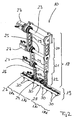
- Figure 5 shows a section 28a, 28b, 28c or 28d of the suction device 28 of the manipulator head 19 with the two respective associated suction nozzles 30.
- the two suction nozzles 30 are fixed to a plate formed as a support member 31, wherein the support member 31 and thus the two suction nozzles 30 in the Suction device 28 are floating. So shows Figure 5 a total of four ball rollers 32, wherein two ball rollers 32 cooperate with an upper side of the support member 31 and two ball rollers 32 with a lower side of the support member 31.
- the cooperating with the underside of the support member 31 ball rollers 32nd are attached to a cross member 33 of the suction device 28, whereas the cooperating with the top of the support member 31 ball rollers 32 are fixed to a support plate 34.
- Fixing pins 35 of a fixing device which are axially displaceable in the direction of the arrows 36, cooperate with the ball rollers 32.
- the fixing bolts 35 penetrate the support element 31 and the cross member 33 and are guided in the cross member 33 associated guide elements 37.
- the fixing bolts 35 the floating bearing of the two suction nozzles 30 free, so that accordingly the support member 31 is tilted together with the suction nozzles 30 to some extent.
- the fixing bolts 35 are opposite the in Figure 5 shown moved downward position so that the fixing bolts 35 associated phases 38 engage in corresponding phases of the support member 31.
- the fixing bolts 35 block the floating support of the support element 31 and thus the suction nozzles 30. If, on the other hand, pressure plates 16 are transferred to a forme cylinder 13 and threaded into a clamping channel of the forme cylinder 13, then the fixing bolts enter 35, the floating mounting of the support member 31 and thus the suction nozzles 30 free.
- a negative pressure in the region of the suction nozzles 30 is provided via compressed air elements 39.
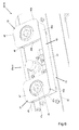
- the stop unit 40 is similar in shape to a pair of glasses.
- the stop unit 40 has two stop elements 41 and 42, which via a web 44 of a base member 43 of the stop unit 40 with each other are connected.
- the base element 43 also has two U-profile-shaped sections 45 and 46, in each of whose web portions 45b and 46b, a circular opening (not shown) is formed, whose diameter is sufficiently large, so that as in Figure 6 shown a respective associated suction nozzle 30 (here a rubber sucker) can freely extend therethrough.
- a respective associated suction nozzle 30 here a rubber sucker
- the web portions 45b, 46b are attached to the cross member 33 of the suction device 28 via fastening means (not shown) such as screws.
- the U-profile-shaped sections 45, 46 furthermore each have two leg sections 45a and 46a, which extend at opposite ends at right angles from the respectively associated web section 45b or 45a. At the free ends of the leg portions 45a and 46a, an elongated projection is formed in each case.
- Each stop element 41, 42 further comprises a stop plate 47 and 48, which in size substantially coincides with the respective associated web portion 45b and 46b and which has a circular opening which is equal in diameter to the opening of the respective web portion 45b, 46b aligned ,
- the respective stop plates 47 and 48 rest on the free ends of the respectively associated leg sections 45a and 46a, respectively, the projections provided on the leg sections 45a and 46a, respectively, engaging in corresponding recesses in the stop plates 47,48.
- the stop plates 47, 48 are attached by means of suitable attachment methods, such as gluing, soldering or welding, to the respective associated leg sections 45a and 46a.
- leg portions 45a and 46a of one side of the respective U-profile-shaped sections 45, 46 are integrally connected to each other via the web 44.
- the leg sections 45a, 46a have such an extension from their respective web section 45b or 46b that the two stop plates 47, 48 are arranged in a common plane.
- the two stopper plates 47, 48 are arranged at such a distance from the traverse 33, that the respective suction nozzle 30 protrudes freely by a predetermined minimum for sucking from the opening of the respective stopper plate 47, 48.
- the pressure plate 16 is aligned parallel to the cross member 33, wherein it is also floatingly supported by the floating mounting of the suction nozzles 30 and the stopper unit 40.
- the stop unit 40 of each section 28a-28d can be brought into a set position in which it limits the suction movement of a handling object sucked in with the suction nozzles 30 of the respective section 28a-28d in the direction of the crossbeam 33, and in FIG a parked position in which it does not limit the suction movement.
- actuators e.g. arranged in the form of pneumatic cylinders (not shown).
- the distance between the stop plates 47, 48 of the cross member 33 is adjustable to such an extent that this or the entire stop unit 40th can be moved as required in the Delivered position and in the parked position or is.
- the leg portions 45a, 46a have such an extent from their respective web portions 45b and 46b, respectively, that the two stop plates 47, 48 are located in the parked position at such a small distance from the crosshead 33 that the respective suction nozzles 30 completely free from the respective openings of the stop plates 47, 48 project, so that when sucking eg a pressure plate 16 this could not come to the stop plates 47, 48 to the plant.
- the stop plates 47, 48 are then at such a distance from the traverse 33 that the suction nozzles 30 project freely again by the minimum amount for suction from the opening of the respective stop plates 47, 48.
- the stop elements 41, 42 and the stop units 40 of all sections 28a-28d on the respective actuators sectionwise or across sections together in the set-position and in the parked position movable.
- all actuators are coupled to a control device, not shown, which can control the actuators accordingly.
- the abutment surfaces 47a, 48a of the stopper plates 47, 48 have a macro roughness for preventing slippage of a sucked handling object, such as e.g. a pressure plate 16, on the contact surfaces 47a, 48a.
- macro-roughness is meant according to the invention a roughness which has such a sufficiently strong stiction between the contact surfaces 47a, 48a and e.g. Ensures a voltage applied to this surface of a pressure plate 16 that a self-locking is guaranteed.
- the macro-roughness is formed by a coating applied to the contact surfaces 47a, 48a.
- a vibration device (not shown) is provided on the manipulator head 19, with which the suction nozzles 30 of all sections 28a-28d are oscillatable together.
- the vibration device is also coupled to the control device so that it can be activated and deactivated.
- a vibration device (not shown) is provided, with which the suction nozzles 30 of the respective sections 28a-28d are vibratable.
- the vibration devices are also coupled to the control device so that they can be separately and jointly activated and deactivated.
- the vibration device or vibration devices can / can be used, for example, to assist in threading the printing plates 16 into the clamping channel of a forme cylinder 13 and when releasing pressure plates 16 glued to the forme cylinder 13.
Landscapes
- Supply, Installation And Extraction Of Printed Sheets Or Plates (AREA)
Applications Claiming Priority (1)
| Application Number | Priority Date | Filing Date | Title |
|---|---|---|---|
| DE102008010598A DE102008010598A1 (de) | 2008-02-22 | 2008-02-22 | Handhabungsvorrichtung einer Druckmaschine |
Publications (1)
| Publication Number | Publication Date |
|---|---|
| EP2093060A1 true EP2093060A1 (fr) | 2009-08-26 |
Family
ID=40622281
Family Applications (1)
| Application Number | Title | Priority Date | Filing Date |
|---|---|---|---|
| EP09152907A Withdrawn EP2093060A1 (fr) | 2008-02-22 | 2009-02-16 | Dispositif de manipulation d'une presse |
Country Status (6)
| Country | Link |
|---|---|
| US (1) | US20090211478A1 (fr) |
| EP (1) | EP2093060A1 (fr) |
| JP (1) | JP2009196360A (fr) |
| CN (1) | CN101554795B (fr) |
| CA (1) | CA2654957A1 (fr) |
| DE (1) | DE102008010598A1 (fr) |
Families Citing this family (4)
| Publication number | Priority date | Publication date | Assignee | Title |
|---|---|---|---|---|
| CA2637371C (fr) * | 2007-07-14 | 2012-07-03 | Manroland Ag | Manipulateur de presse a imprimer |
| DE102013017728B4 (de) * | 2013-10-23 | 2015-05-07 | Beumer Gmbh & Co. Kg | Sauggreifvorrichtung |
| DE102014102791A1 (de) * | 2014-03-03 | 2015-09-03 | Bayerische Motoren Werke Aktiengesellschaft | Vakuumgreifer |
| CN109867140A (zh) * | 2019-04-15 | 2019-06-11 | 常州纺织服装职业技术学院 | 一种钢水取样杯自动送料装置 |
Citations (3)
| Publication number | Priority date | Publication date | Assignee | Title |
|---|---|---|---|---|
| WO2005110754A1 (fr) * | 2004-05-10 | 2005-11-24 | Maschinenfabrik Wifag | Machine a imprimer comprenant un dispositif d'aspiration, dispositif d'aspiration et procede pour remplacer une garniture d'impression |
| EP1652667A2 (fr) * | 2004-10-26 | 2006-05-03 | Maschinenfabrik Wifag | Manipulateur de plaques d'impression |
| DE202006020088U1 (de) | 2006-11-22 | 2007-12-27 | Man Roland Druckmaschinen Ag | Handhabungsvorrichtung einer Druckmaschine |
Family Cites Families (10)
| Publication number | Priority date | Publication date | Assignee | Title |
|---|---|---|---|---|
| JPS62215117A (ja) * | 1986-03-17 | 1987-09-21 | 新技術事業団 | 負圧吸着装置 |
| JP3197019B2 (ja) * | 1991-03-18 | 2001-08-13 | 株式会社ブリヂストン | 帯状部材の吸着方法 |
| DE4116491C1 (fr) * | 1991-05-21 | 1992-06-17 | Heidelberger Druckmaschinen Ag, 6900 Heidelberg, De | |
| DE4214047A1 (de) * | 1992-04-29 | 1993-11-04 | Heidelberger Druckmasch Ag | Halteeinrichtung fuer eine zu verschiebende platte |
| AUPN559095A0 (en) * | 1995-09-22 | 1995-10-19 | Cherrington (Australia) Pty Ltd | Pipe protector |
| DE19620997C2 (de) * | 1996-05-24 | 1998-03-26 | Koenig & Bauer Albert Ag | Verfahren und Vorrichtung zum axialen Positionieren einer Druckplatte |
| DE29906611U1 (de) * | 1999-04-14 | 1999-09-02 | J. Schmalz GmbH, 72293 Glatten | Sauggreifer |
| JP4291497B2 (ja) * | 2000-05-11 | 2009-07-08 | 株式会社妙徳 | 吸着パッド |
| DE102006010701B4 (de) * | 2005-03-17 | 2008-09-25 | Daimler Ag | Handhabungseinrichtung zum Transportieren flacher Werkstücke in einer Pressenanlage |
| CA2637371C (fr) * | 2007-07-14 | 2012-07-03 | Manroland Ag | Manipulateur de presse a imprimer |
-
2008
- 2008-02-22 DE DE102008010598A patent/DE102008010598A1/de not_active Withdrawn
-
2009
- 2009-02-16 EP EP09152907A patent/EP2093060A1/fr not_active Withdrawn
- 2009-02-19 JP JP2009036570A patent/JP2009196360A/ja active Pending
- 2009-02-20 CA CA002654957A patent/CA2654957A1/fr not_active Abandoned
- 2009-02-20 CN CN2009100078876A patent/CN101554795B/zh not_active Expired - Fee Related
- 2009-02-23 US US12/390,548 patent/US20090211478A1/en not_active Abandoned
Patent Citations (3)
| Publication number | Priority date | Publication date | Assignee | Title |
|---|---|---|---|---|
| WO2005110754A1 (fr) * | 2004-05-10 | 2005-11-24 | Maschinenfabrik Wifag | Machine a imprimer comprenant un dispositif d'aspiration, dispositif d'aspiration et procede pour remplacer une garniture d'impression |
| EP1652667A2 (fr) * | 2004-10-26 | 2006-05-03 | Maschinenfabrik Wifag | Manipulateur de plaques d'impression |
| DE202006020088U1 (de) | 2006-11-22 | 2007-12-27 | Man Roland Druckmaschinen Ag | Handhabungsvorrichtung einer Druckmaschine |
Non-Patent Citations (2)
| Title |
|---|
| "Roboterarm für Plattenwechsel in Zeitungsrotationen", DEUTSCHER DRUCKER, no. 17, 31 May 2007 (2007-05-31), Deutschland, pages 20, XP007908649 * |
| DEUTSCHER DRUCKER, 31 May 2007 (2007-05-31) |
Also Published As
| Publication number | Publication date |
|---|---|
| DE102008010598A1 (de) | 2009-08-27 |
| US20090211478A1 (en) | 2009-08-27 |
| CN101554795B (zh) | 2012-03-21 |
| JP2009196360A (ja) | 2009-09-03 |
| CA2654957A1 (fr) | 2009-08-22 |
| CN101554795A (zh) | 2009-10-14 |
Similar Documents
| Publication | Publication Date | Title |
|---|---|---|
| EP2017081B1 (fr) | Dispositif de manipulation d'une presse d' impression | |
| DE202007018706U1 (de) | Druckeinheiten mit mehreren Druckwerken sowie Druckturm | |
| EP2093060A1 (fr) | Dispositif de manipulation d'une presse | |
| EP2792487A1 (fr) | Tamis de sérigraphie rotative, dispositif de montage, dispositif de revetement, dispositif d'éclairage et dispositif de lavage doté d'une fermeture de serrage rapide | |
| DE10238123A1 (de) | Vorrichtungen zum Montieren einer Druckform auf einem Formzylinder einer Druckmaschine | |
| EP1530515B1 (fr) | Procede de remplacement d'au moins un bloc d'impression d'une machine a imprimer comportant plusieurs cylindres graves | |
| EP1927474B1 (fr) | Presse d'impression avec dispositif de manipulation | |
| EP1530514B1 (fr) | Procede permettant de monter un habillage sur le cylindre d'une machine a imprimer | |
| DE10238177B3 (de) | Vorrichtung zum Andrücken eines Aufzugs an einen Zylinder einer Druckmaschine mit Hilfe von in Umfangsrichtung des Zylinders voneinander beabstandeten ersten und zweiten Wälzelementen | |
| DE102007032941A1 (de) | Handhabungsvorrichtung einer Druckmaschine | |
| DE19941633C2 (de) | Verfahren und Einrichtung zum Einstellen und Wechseln von Saugringen | |
| DE10238125B3 (de) | Druckformmagazin mit mindestens einem Schacht | |
| EP0875378B1 (fr) | Dispositif de serrage | |
| DE102006006331B3 (de) | Vorrichtung zum Befestigen eines Aufzugs auf einem Zylinder | |
| DE102006050568B3 (de) | Vorrichtung zum Andrücken eines Aufzugs an einen Zylinder | |
| DE202023105103U1 (de) | Druckwerk mit verfahrbar angeordneten Druckzylindern | |
| EP1531994B1 (fr) | Procede et dispositif permettant de retirer l'habillage d'un cylindre d'une machine a imprimer | |
| EP1900525A2 (fr) | Dispositif destiné au montage d'une plaque d'impression sur un cylindre porte-plaque d'une machine d'impression | |
| DE102023123902A1 (de) | Druckwerk mit verfahrbar angeordneten Druckzylindern | |
| DE102011084005B4 (de) | Verfahren zum Ausrichten einer Speichervorrichtung und einer zu dieser Speichervorrichtung gehörenden Fördereinrichtung jeweils relativ zu einem in einer Druckeinheit angeordneten Formzylinder | |
| DE202006020087U1 (de) | Handhabungsvorrichtung einer Druckmaschine | |
| DE29615995U1 (de) | Vorrichtung zum Aufziehen flexibler Druckformen | |
| DE10238106A1 (de) | Verfahren und Vorrichtung zum Montieren eines Aufzugs auf einen Zylinder einer Druckmaschine | |
| DE10238107A1 (de) | Verfahren und Vorrichtungen zum Abnehmen eines Aufzugs von einem Zylinder einer Druckmaschine | |
| DE29911599U1 (de) | Vorrichtung zum axialen Verschieben eines Gummituches |
Legal Events
| Date | Code | Title | Description |
|---|---|---|---|
| PUAI | Public reference made under article 153(3) epc to a published international application that has entered the european phase |
Free format text: ORIGINAL CODE: 0009012 |
|
| AK | Designated contracting states |
Kind code of ref document: A1 Designated state(s): AT BE BG CH CY CZ DE DK EE ES FI FR GB GR HR HU IE IS IT LI LT LU LV MC MK MT NL NO PL PT RO SE SI SK TR |
|
| AX | Request for extension of the european patent |
Extension state: AL BA RS |
|
| 17P | Request for examination filed |
Effective date: 20100218 |
|
| 17Q | First examination report despatched |
Effective date: 20100318 |
|
| AKX | Designation fees paid |
Designated state(s): AT BE BG CH CY CZ DE DK EE ES FI FR GB GR HR HU IE IS IT LI LT LU LV MC MK MT NL NO PL PT RO SE SI SK TR |
|
| 19U | Interruption of proceedings before grant |
Effective date: 20120201 |
|
| 19W | Proceedings resumed before grant after interruption of proceedings |
Effective date: 20140203 |
|
| STAA | Information on the status of an ep patent application or granted ep patent |
Free format text: STATUS: THE APPLICATION HAS BEEN WITHDRAWN |
|
| 18W | Application withdrawn |
Effective date: 20140311 |