EP2093067A2 - Imprimante dotée d'une tête d'éclairage - Google Patents
Imprimante dotée d'une tête d'éclairage Download PDFInfo
- Publication number
- EP2093067A2 EP2093067A2 EP09007261A EP09007261A EP2093067A2 EP 2093067 A2 EP2093067 A2 EP 2093067A2 EP 09007261 A EP09007261 A EP 09007261A EP 09007261 A EP09007261 A EP 09007261A EP 2093067 A2 EP2093067 A2 EP 2093067A2
- Authority
- EP
- European Patent Office
- Prior art keywords
- lamp
- exposure head
- reflectors
- printer according
- printer
- Prior art date
- Legal status (The legal status is an assumption and is not a legal conclusion. Google has not performed a legal analysis and makes no representation as to the accuracy of the status listed.)
- Granted
Links
- 238000001816 cooling Methods 0.000 claims abstract description 11
- 230000005855 radiation Effects 0.000 claims description 22
- 238000007639 printing Methods 0.000 claims description 19
- QSHDDOUJBYECFT-UHFFFAOYSA-N mercury Chemical compound [Hg] QSHDDOUJBYECFT-UHFFFAOYSA-N 0.000 claims description 3
- 238000007599 discharging Methods 0.000 claims description 2
- 238000001035 drying Methods 0.000 abstract 1
- 239000011521 glass Substances 0.000 description 3
- 238000004891 communication Methods 0.000 description 2
- 238000000034 method Methods 0.000 description 2
- 230000001681 protective effect Effects 0.000 description 2
- 238000000137 annealing Methods 0.000 description 1
- 230000000740 bleeding effect Effects 0.000 description 1
- 239000000969 carrier Substances 0.000 description 1
- 238000010276 construction Methods 0.000 description 1
- 238000011109 contamination Methods 0.000 description 1
- 239000002826 coolant Substances 0.000 description 1
- 230000006378 damage Effects 0.000 description 1
- 230000001419 dependent effect Effects 0.000 description 1
- 238000009795 derivation Methods 0.000 description 1
- 239000012530 fluid Substances 0.000 description 1
- 230000017525 heat dissipation Effects 0.000 description 1
- 238000010438 heat treatment Methods 0.000 description 1
- 238000005286 illumination Methods 0.000 description 1
- 238000004519 manufacturing process Methods 0.000 description 1
- 239000011159 matrix material Substances 0.000 description 1
- 238000007645 offset printing Methods 0.000 description 1
- 230000008092 positive effect Effects 0.000 description 1
- 238000005057 refrigeration Methods 0.000 description 1
- 230000003685 thermal hair damage Effects 0.000 description 1
- 238000011144 upstream manufacturing Methods 0.000 description 1
Images


Classifications
-
- G—PHYSICS
- G03—PHOTOGRAPHY; CINEMATOGRAPHY; ANALOGOUS TECHNIQUES USING WAVES OTHER THAN OPTICAL WAVES; ELECTROGRAPHY; HOLOGRAPHY
- G03G—ELECTROGRAPHY; ELECTROPHOTOGRAPHY; MAGNETOGRAPHY
- G03G15/00—Apparatus for electrographic processes using a charge pattern
- G03G15/20—Apparatus for electrographic processes using a charge pattern for fixing, e.g. by using heat
- G03G15/2003—Apparatus for electrographic processes using a charge pattern for fixing, e.g. by using heat using heat
- G03G15/2007—Apparatus for electrographic processes using a charge pattern for fixing, e.g. by using heat using heat using radiant heat, e.g. infrared lamps, microwave heaters
-
- B—PERFORMING OPERATIONS; TRANSPORTING
- B41—PRINTING; LINING MACHINES; TYPEWRITERS; STAMPS
- B41J—TYPEWRITERS; SELECTIVE PRINTING MECHANISMS, i.e. MECHANISMS PRINTING OTHERWISE THAN FROM A FORME; CORRECTION OF TYPOGRAPHICAL ERRORS
- B41J11/00—Devices or arrangements of selective printing mechanisms, e.g. ink-jet printers or thermal printers, for supporting or handling copy material in sheet or web form
- B41J11/0015—Devices or arrangements of selective printing mechanisms, e.g. ink-jet printers or thermal printers, for supporting or handling copy material in sheet or web form for treating before, during or after printing or for uniform coating or laminating the copy material before or after printing
- B41J11/002—Curing or drying the ink on the copy materials, e.g. by heating or irradiating
- B41J11/0021—Curing or drying the ink on the copy materials, e.g. by heating or irradiating using irradiation
-
- B—PERFORMING OPERATIONS; TRANSPORTING
- B41—PRINTING; LINING MACHINES; TYPEWRITERS; STAMPS
- B41J—TYPEWRITERS; SELECTIVE PRINTING MECHANISMS, i.e. MECHANISMS PRINTING OTHERWISE THAN FROM A FORME; CORRECTION OF TYPOGRAPHICAL ERRORS
- B41J11/00—Devices or arrangements of selective printing mechanisms, e.g. ink-jet printers or thermal printers, for supporting or handling copy material in sheet or web form
- B41J11/0015—Devices or arrangements of selective printing mechanisms, e.g. ink-jet printers or thermal printers, for supporting or handling copy material in sheet or web form for treating before, during or after printing or for uniform coating or laminating the copy material before or after printing
- B41J11/002—Curing or drying the ink on the copy materials, e.g. by heating or irradiating
- B41J11/0021—Curing or drying the ink on the copy materials, e.g. by heating or irradiating using irradiation
- B41J11/00218—Constructional details of the irradiation means, e.g. radiation source attached to reciprocating print head assembly or shutter means provided on the radiation source
-
- F—MECHANICAL ENGINEERING; LIGHTING; HEATING; WEAPONS; BLASTING
- F26—DRYING
- F26B—DRYING SOLID MATERIALS OR OBJECTS BY REMOVING LIQUID THEREFROM
- F26B3/00—Drying solid materials or objects by processes involving the application of heat
- F26B3/28—Drying solid materials or objects by processes involving the application of heat by radiation, e.g. from the sun
Definitions
- the invention relates to a printer, in particular a serial printer, with an exposure head for the exposure of printed images with light-curing ink.
- Serial printers or line printers are printers that print characters one after the other within a single line. They are inexpensive to manufacture, reliable in operation and small in size, so that they are suitable as Auftischonul. Printers of this type are widely used as type printers, dot matrix printers or as ink printers. If light-curing ink is used in an ink printer, then an exposure head guided on a carriage is required in addition to the print head, which exposes and cures the printed image after printing with high radiation intensity.
- the printer according to the invention has an exposure head for exposure of printed images with an exposure head housing, in which a lamp is at least partially surrounded by reflectors, which emits radiation during operation, which by the reflectors is passed to a printable with light-curing ink print image plane.
- a lamp is at least partially surrounded by reflectors, which emits radiation during operation, which by the reflectors is passed to a printable with light-curing ink print image plane.
- the combination of the geometrically different reflectors a far greater part of the radiation emitted by the lamp in all directions is directed to the print image plane than by elliptical reflectors alone.
- This can be achieved by arranging the planar reflectors on opposite side walls of the exposure head housing and are designed as cross reflectors.
- the edge region which is typically formed with a lower radiation intensity with respect to the center region, is irradiated more intensely by the printing image plane.
- the reflection surfaces of the cross reflectors are inclined relative to the main beam direction of the lamp, that the focused beam area is reinforced at the edge in the print line direction by the reflected image of the lamp in the focal plane.
- the cross reflectors In order to increase the edge area of the illuminated print image section, it is advantageously provided that the cross reflectors, viewed from the lamp in the direction of the print image plane, run apart like a funnel. By enlarging the illuminated print image section, the residence time required to cure the ink is reduced. Therefore, the printing speed of the printer can be increased.
- the planar reflectors are arranged on the opposite side of the lamp to the printing image plane and are designed as reflector elements. By means of these reflector elements, the radiation emitted by the lamp in the direction opposite to the printing image plane is directed onto the printing image plane. In this way, in addition to the increase of the radiation intensity on the print image plane is achieved that the heating of the exposure head housing is reduced by the radiation of the lamp.
- the reflector elements extend in the transverse direction of the lamp, starting from the elliptical reflectors and / or cross-reflectors. Furthermore, it is preferred that the lamp is positioned in a first focal point of the elliptical reflectors. Finally, it is preferred that the elliptical reflectors, the lamp and the print image plane are arranged relative to one another in such a way that a second focal point of the elliptical reflectors is in the region of the print image plane.
- the invention is a printer with an exposure head for exposure of printed images and a Exposure head housing provided in which a reflector is at least partially surrounded lamp is arranged, which emits radiation during operation, which is passed through the reflectors on a light-curing ink printable image plane.
- the invention provides that a fan unit is connected via at least one air duct with the exposure head, wherein the air duct opens into a cooling air space between the reflectors and the side walls of the exposure head housing.
- the luminous element of the lamp is located in an interior space insulated from the reflectors.
- intensive cooling of the lighting head is achieved in the smallest space.
- the lamp is mounted in the exposure head housing via at least one lamp socket, the lamp socket protruding into the air duct. This effectively cools the lampholder in the airflow and effectively reduces heat dissipation to the exposure head housing.
- This air guide is particularly important when using a mercury vapor lamp with operating temperatures of about 900 ° C, to prevent the exposure head housing is thermally damaged.
- a particularly advantageous embodiment of the invention provides that in the printer housing a blow-out for discharging heated exhaust air is provided, which is preferably arranged corresponding to the outlet opening of the air duct of the exposure head housing. This ensures that the loss heat produced in the exposure head housing by its lamp in its operation can be transported via a cooling medium such as air, for example, into the environment.
- the invention relates to a printer, preferably a serial printer with a printer housing, in which an exposure head is mounted.
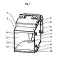
- the exposure head is the essential component of the invention. Therefore, the figures show only the exposure head and not the printer.
- the exposure head comprises an exposure head housing with elbows (1, 2). On the angle pieces (1, 2) a printed circuit board (3) with plug (4) and designed as a fan unit fan (10) with filter (5) are placed. Side of the two angle pieces (1, 2) identical exhaust air ducts (6, 7) are mounted, the removable segments (8, 9) have. By mutual removal of the segments (8, 9) in the exhaust air ducts (6, 7) arise output openings through which heated in the exposure head exhaust air (44) can be selectively blown on one side of the exposure head housing. At least one of these outlet openings is in fluid communication with a correspondingly provided in the printer housing discharge opening to convey the heated exhaust air from the printer, eg. In the environment.
- the printer housing are mounted as a guide means for the exposure head and a printer head with light-curing ink slide or rails over which the exposure head and the printer head during the printing process of the printer, controlled by a drive, is moved traversing between two lateral end positions.
- the printer housing has only one exhaust opening.
- the discharge opening of the printer housing and the outlet opening the exhaust duct (6, 7) are arranged to each other such that the openings are in flow connection in an end position of the exposure head. In this position, the exposure head is briefly stopped during printing and the heated exhaust air is blown out of the printer housing.
- the exposure head additionally contains elliptical reflectors (11, 12) and cross reflectors (13, 14).
- the light exit opening is covered by a glass pane (15), which is secured by the spring elements (16, 17) lying in the beam shadow.
- a lamp (18) of the exposure head is not shown in this view.
- the exposure head housing is essentially formed by the two identical angle pieces (1, 2), which are firmly connected to each other.
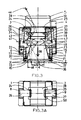
- two ellipse carriers (20, 21) are inserted at a distance (19), each containing two elliptical recesses (22, 23).
- the elliptical reflectors (11, 12) are inserted from the light exit side. Since the recesses (22, 23) are only slightly wider than the thickness of the elliptical reflectors (11, 12), these have after mounting the exact calculated geometric shape on its reflector surface.
- For mounting and power supply are designated at 24 and 25 angled inner lobes of the angle pieces (1, 2) on both sides lamp sockets (26, 27) attached.
- a protective shield (28) which shields the scattered radiation of the lamp (18) towards the top and in addition the two inner tabs (24, 25) of the angle pieces (1, 2) against forces of socket springs (29, 30) stabilized.
- the printed circuit board (3) with the plug (4) for the electrical supply of the exposure head is provided, which is covered by the fan (10) with the upstream air filter (5).
- the light exit opening of the exposure head is covered with the glass pane (15) against contamination and damage.
- the glass pane (15) is held by spring elements (16, 17), which are engaged in the radiation shadow behind an angled bend (31, 32) of the elliptical reflectors (1, 2).
- the cooling air flow in the exposure head is three-dimensional and is shown for one side by the dashed line (44).
- the cooling air duct is mirror-inverted.
- the lamp (18) emits light uniformly on all sides on its cylindrical jacket. It is arranged in a first focal point (34) of the elliptical reflectors (11, 12). In a second focal point (35) is a printing image plane (40) of the printer. Above the lamp (18), the cross reflectors (13, 14) have a region (36, 37) formed as reflector elements. This is inclined to the main beam axis (38) in such a way that the reflected radiation (49) is largely radiated past the luminous element (39) of the lamp (18) in order not to unnecessarily heat it and to reflect it Use radiation (49) in addition to the exposure of the image plane (40).
- the light radiated radially by the luminous element (39) of the lamp (18) is focused by the elliptical reflectors (11, 12) in a region (45) of the printing image plane (40) and thus by a direct comparison with the direct radiation of the lamp (18) Multiple amplified.
- this region (45) with a higher irradiance in the direction of the longitudinal axis of the lamp (18) is only as long as the luminous element (39) of the lamp (18).
- the longest possible exposure zone with a corresponding exposure intensity in the printing image plane (40) in the printing direction is advantageous.
- the cross reflectors (13, 14) are inclined obliquely to the main beam direction (38) of the lamp (18) to the extent that the reflected images (46) of the filament (39) through the cross reflectors (13, 14 ) are respectively imaged on the printing image plane (40) following the area (45) produced by the elliptical reflectors (11, 12) with high light intensity.
- the image plane is only 1 to 2 mm away from the illumination head.
- the exposure head and the fan unit are connected to each other via an air duct, which along the Guided by 44 dashed line.
- the air duct is guided past the luminous element (39) of the lamp (18), with the lamp socket (26, 27) protruding into the air duct.
- This opens into a cooling air space (48) between the reflectors (11, 12, 13, 14) and the side walls of the exposure head housing and is in communication with the exhaust air duct (7, 8) in flow connection.
Landscapes
- Engineering & Computer Science (AREA)
- General Health & Medical Sciences (AREA)
- Toxicology (AREA)
- Health & Medical Sciences (AREA)
- Mechanical Engineering (AREA)
- Microbiology (AREA)
- Life Sciences & Earth Sciences (AREA)
- General Engineering & Computer Science (AREA)
- Physics & Mathematics (AREA)
- General Physics & Mathematics (AREA)
- Exposure And Positioning Against Photoresist Photosensitive Materials (AREA)
- Accessory Devices And Overall Control Thereof (AREA)
- Ink Jet (AREA)
- Facsimile Heads (AREA)
Applications Claiming Priority (2)
| Application Number | Priority Date | Filing Date | Title |
|---|---|---|---|
| DE102006003057A DE102006003057A1 (de) | 2006-01-20 | 2006-01-20 | Drucker mit einem Belichtungskopf |
| EP07722749A EP1976704B1 (fr) | 2006-01-20 | 2007-01-09 | Imprimante dotée d'une tête d'exposition |
Related Parent Applications (3)
| Application Number | Title | Priority Date | Filing Date |
|---|---|---|---|
| EP07722749A Division EP1976704B1 (fr) | 2006-01-20 | 2007-01-09 | Imprimante dotée d'une tête d'exposition |
| EP07722749A Division-Into EP1976704B1 (fr) | 2006-01-20 | 2007-01-09 | Imprimante dotée d'une tête d'exposition |
| EP07722749.4 Division | 2007-01-09 |
Publications (3)
| Publication Number | Publication Date |
|---|---|
| EP2093067A2 true EP2093067A2 (fr) | 2009-08-26 |
| EP2093067A3 EP2093067A3 (fr) | 2010-10-27 |
| EP2093067B1 EP2093067B1 (fr) | 2012-10-24 |
Family
ID=38137727
Family Applications (2)
| Application Number | Title | Priority Date | Filing Date |
|---|---|---|---|
| EP09007261A Not-in-force EP2093067B1 (fr) | 2006-01-20 | 2007-01-09 | Imprimante dotée d'une tête d'éclairage |
| EP07722749A Not-in-force EP1976704B1 (fr) | 2006-01-20 | 2007-01-09 | Imprimante dotée d'une tête d'exposition |
Family Applications After (1)
| Application Number | Title | Priority Date | Filing Date |
|---|---|---|---|
| EP07722749A Not-in-force EP1976704B1 (fr) | 2006-01-20 | 2007-01-09 | Imprimante dotée d'une tête d'exposition |
Country Status (7)
| Country | Link |
|---|---|
| US (1) | US8016407B2 (fr) |
| EP (2) | EP2093067B1 (fr) |
| JP (1) | JP5162472B2 (fr) |
| CN (1) | CN101370668B (fr) |
| DE (1) | DE102006003057A1 (fr) |
| ES (2) | ES2394600T3 (fr) |
| WO (1) | WO2007087958A2 (fr) |
Families Citing this family (3)
| Publication number | Priority date | Publication date | Assignee | Title |
|---|---|---|---|---|
| GB2468702A (en) * | 2009-03-19 | 2010-09-22 | Gew | Ink curing apparatus with integrally formed reflector and cooling means |
| WO2014119500A1 (fr) * | 2013-01-30 | 2014-08-07 | 京セラ株式会社 | Dispositif de rayonnement lumineux et dispositif d'impression |
| JP6111785B2 (ja) * | 2013-03-28 | 2017-04-12 | セイコーエプソン株式会社 | 液体吐出装置 |
Citations (2)
| Publication number | Priority date | Publication date | Assignee | Title |
|---|---|---|---|---|
| FR2234966A1 (fr) | 1973-06-27 | 1975-01-24 | Behrens Joh | |
| US20020101491A1 (en) | 2001-01-30 | 2002-08-01 | Robert Ervin | Compact microwave-powered lamp, inkjet printer using this lamp, and ultraviolet light curing using this lamp |
Family Cites Families (36)
| Publication number | Priority date | Publication date | Assignee | Title |
|---|---|---|---|---|
| GB1397077A (en) * | 1971-07-16 | 1975-06-11 | Hanovia Lamps Ltd | Ink drying reflector system |
| DE7343809U (de) * | 1973-12-10 | 1975-03-13 | Geyer D | Ultraviolettstrahllampe |
| FR2334966A1 (fr) | 1975-12-08 | 1977-07-08 | Scal Gp Condit Aluminium | Reflecteur cylindro-elliptique |
| US4434562A (en) * | 1981-09-02 | 1984-03-06 | American Screen Printing Equipment Company | Curing apparatus and method |
| JPH0525911Y2 (fr) * | 1987-06-03 | 1993-06-30 | ||
| JPH0544817Y2 (fr) * | 1988-10-04 | 1993-11-15 | ||
| JPH02145460A (ja) * | 1988-11-24 | 1990-06-04 | Furukawa Electric Co Ltd:The | 光ファイバ被覆方法 |
| JPH04283723A (ja) * | 1991-03-12 | 1992-10-08 | Mitsubishi Electric Corp | 液晶表示装置用冷却装置 |
| US5586013A (en) * | 1991-07-19 | 1996-12-17 | Minnesota Mining And Manufacturing Company | Nonimaging optical illumination system |
| GB2280947B (en) | 1991-07-25 | 1995-06-07 | G E W | U.V. Dryers |
| JPH05283545A (ja) * | 1992-03-31 | 1993-10-29 | Toshiba Lighting & Technol Corp | 紫外線照射装置 |
| JPH0691856A (ja) * | 1992-09-10 | 1994-04-05 | Toshiba Lighting & Technol Corp | 紫外線照射装置および印刷機 |
| JPH0855502A (ja) * | 1994-08-11 | 1996-02-27 | Koito Mfg Co Ltd | 車両用灯具 |
| JPH10302522A (ja) * | 1997-04-30 | 1998-11-13 | Fujitsu Ltd | 光源の冷却構造と投写型液晶表示装置 |
| ATE224523T1 (de) | 1997-05-26 | 2002-10-15 | Uviterno Ag | Vorrichtung zum bestrahlen eines substrats mittels uv-strahlen und verfahren zum betrieb der vorrichtung |
| US6102547A (en) * | 1997-08-01 | 2000-08-15 | Olympus Optical Co., Ltd. | Illumination device |
| US5861633A (en) * | 1997-08-04 | 1999-01-19 | Con-Trol-Cure, Inc. | Irradiator apparatus |
| JP2000316380A (ja) * | 1999-05-12 | 2000-11-21 | Koito Ind Ltd | 植物育成装置 |
| US6657722B1 (en) * | 1999-06-21 | 2003-12-02 | Kabushikaisha Kajitsuhihakaihinshitsukenkyujo | Side multiple-lamp type on-line inside quality inspecting device |
| JP2001143523A (ja) * | 1999-11-17 | 2001-05-25 | Mitsubishi Electric Corp | 光源装置 |
| JP2001351409A (ja) * | 2000-06-02 | 2001-12-21 | Stanley Electric Co Ltd | 車両用照明灯具 |
| JP2002156691A (ja) * | 2000-11-21 | 2002-05-31 | Canon Inc | 照明装置および撮影装置 |
| US7073901B2 (en) * | 2001-04-13 | 2006-07-11 | Electronics For Imaging, Inc. | Radiation treatment for ink jet fluids |
| JP3481219B2 (ja) * | 2001-07-19 | 2003-12-22 | 三洋電機株式会社 | 光源装置及び該光源装置を用いた投写型表示装置 |
| JP2004001328A (ja) * | 2002-06-03 | 2004-01-08 | Mutoh Ind Ltd | インクジェット記録装置 |
| US6739716B2 (en) * | 2002-06-10 | 2004-05-25 | Océ Display Graphics Systems, Inc. | Systems and methods for curing a fluid |
| US6649921B1 (en) | 2002-08-19 | 2003-11-18 | Fusion Uv Systems, Inc. | Apparatus and method providing substantially two-dimensionally uniform irradiation |
| JP2004181941A (ja) * | 2002-11-20 | 2004-07-02 | Konica Minolta Holdings Inc | インクジェットプリンタ及び紫外線照射装置 |
| JP4259099B2 (ja) * | 2002-11-21 | 2009-04-30 | コニカミノルタホールディングス株式会社 | インクジェットプリンタ |
| JP4309688B2 (ja) * | 2003-03-20 | 2009-08-05 | セーレン株式会社 | 紫外線硬化型インクジェット記録装置 |
| JP2005125753A (ja) * | 2003-09-30 | 2005-05-19 | Konica Minolta Medical & Graphic Inc | インクジェット記録装置 |
| US7137695B2 (en) * | 2003-09-30 | 2006-11-21 | Konica Minolta Medical & Graphics, Inc. | Inkjet recording apparatus |
| US7144135B2 (en) * | 2003-11-26 | 2006-12-05 | Philips Lumileds Lighting Company, Llc | LED lamp heat sink |
| JP2005262588A (ja) * | 2004-03-17 | 2005-09-29 | Matsushita Electric Ind Co Ltd | 製版装置 |
| JP4053016B2 (ja) * | 2004-03-26 | 2008-02-27 | 三洋電機株式会社 | ランプユニット |
| US7828411B2 (en) * | 2006-02-27 | 2010-11-09 | Fujifilm Corporation | Liquid ejection method, liquid ejection apparatus, double-side printing method and image recording apparatus for double-side printing |
-
2006
- 2006-01-20 DE DE102006003057A patent/DE102006003057A1/de not_active Withdrawn
-
2007
- 2007-01-09 CN CN2007800027695A patent/CN101370668B/zh not_active Expired - Fee Related
- 2007-01-09 ES ES09007261T patent/ES2394600T3/es active Active
- 2007-01-09 WO PCT/EP2007/000113 patent/WO2007087958A2/fr not_active Ceased
- 2007-01-09 EP EP09007261A patent/EP2093067B1/fr not_active Not-in-force
- 2007-01-09 US US12/161,670 patent/US8016407B2/en not_active Expired - Fee Related
- 2007-01-09 EP EP07722749A patent/EP1976704B1/fr not_active Not-in-force
- 2007-01-09 JP JP2008550663A patent/JP5162472B2/ja not_active Expired - Fee Related
- 2007-01-09 ES ES07722749T patent/ES2395562T3/es active Active
Patent Citations (2)
| Publication number | Priority date | Publication date | Assignee | Title |
|---|---|---|---|---|
| FR2234966A1 (fr) | 1973-06-27 | 1975-01-24 | Behrens Joh | |
| US20020101491A1 (en) | 2001-01-30 | 2002-08-01 | Robert Ervin | Compact microwave-powered lamp, inkjet printer using this lamp, and ultraviolet light curing using this lamp |
Also Published As
| Publication number | Publication date |
|---|---|
| JP2009523627A (ja) | 2009-06-25 |
| EP2093067B1 (fr) | 2012-10-24 |
| WO2007087958A3 (fr) | 2007-11-15 |
| JP5162472B2 (ja) | 2013-03-13 |
| DE102006003057A1 (de) | 2007-07-26 |
| CN101370668B (zh) | 2012-11-07 |
| EP1976704A2 (fr) | 2008-10-08 |
| US8016407B2 (en) | 2011-09-13 |
| EP2093067A3 (fr) | 2010-10-27 |
| EP1976704B1 (fr) | 2012-10-24 |
| ES2394600T3 (es) | 2013-02-04 |
| CN101370668A (zh) | 2009-02-18 |
| US20100220171A1 (en) | 2010-09-02 |
| WO2007087958A2 (fr) | 2007-08-09 |
| ES2395562T3 (es) | 2013-02-13 |
Similar Documents
| Publication | Publication Date | Title |
|---|---|---|
| DE19733496B4 (de) | Lampenaufbau | |
| EP2992744B1 (fr) | Dispositif pour sécher et fritter une encre à teneur métallique sur un substrat | |
| DE112014002932T5 (de) | Lüftung mit interner Ablenkung | |
| DE2923784A1 (de) | Haartrockner | |
| DE102015121819B4 (de) | Scheinwerfer | |
| DE102014209320B4 (de) | Fahrzeugleuchte | |
| WO2005105448A2 (fr) | Dispositif d'exposition aux rayons ultraviolets | |
| WO2007087791A1 (fr) | Phare de véhicule à moteur | |
| DE212013000076U1 (de) | Deflektoren für ein Beleuchtungsmodul | |
| EP2093067B1 (fr) | Imprimante dotée d'une tête d'éclairage | |
| DE4301718A1 (de) | UV-Bestrahlungseinrichtung | |
| EP2844474B1 (fr) | Appareil d'éclairage à réflecteur | |
| DE102020103763B4 (de) | Lichtbeleuchtungsvorrichtung | |
| DE3525482C1 (de) | Belichtungsvorrichtung | |
| DE212013000050U1 (de) | Lampenbelüftungssystem | |
| EP2012057A1 (fr) | Luminaire | |
| DE202022003362U1 (de) | Haarentfernungsvorrichtung | |
| DE4333448A1 (de) | Verfahren und Vorrichtung zur Vermeidung einer Rückströmung in luft- oder gasgekühlten Lampen | |
| EP3542098B1 (fr) | Dissipateur thermique à résistance thermique variable | |
| DE2422873C3 (de) | Vorrichtung zum Trocknen bedruckter Bahnen | |
| EP3115679B1 (fr) | Dispositif d'eclairage et vehicule comprenant le dispositif d'eclairage | |
| EP1902252A1 (fr) | Systeme de refroidissement pour un projecteur | |
| DE2723228C2 (de) | Episkop | |
| DE1115656B (de) | Reflektoranordnung fuer langgestreckte, roehrenfoermige Lichtquellen | |
| DE202024104938U1 (de) | Leuchte sowie Kühlkörper für eine Leuchte |
Legal Events
| Date | Code | Title | Description |
|---|---|---|---|
| PUAI | Public reference made under article 153(3) epc to a published international application that has entered the european phase |
Free format text: ORIGINAL CODE: 0009012 |
|
| 17P | Request for examination filed |
Effective date: 20090530 |
|
| AC | Divisional application: reference to earlier application |
Ref document number: 1976704 Country of ref document: EP Kind code of ref document: P |
|
| AK | Designated contracting states |
Kind code of ref document: A2 Designated state(s): ES FR GB IT |
|
| PUAL | Search report despatched |
Free format text: ORIGINAL CODE: 0009013 |
|
| AK | Designated contracting states |
Kind code of ref document: A3 Designated state(s): ES FR GB IT |
|
| 17Q | First examination report despatched |
Effective date: 20111212 |
|
| GRAP | Despatch of communication of intention to grant a patent |
Free format text: ORIGINAL CODE: EPIDOSNIGR1 |
|
| GRAS | Grant fee paid |
Free format text: ORIGINAL CODE: EPIDOSNIGR3 |
|
| GRAA | (expected) grant |
Free format text: ORIGINAL CODE: 0009210 |
|
| AC | Divisional application: reference to earlier application |
Ref document number: 1976704 Country of ref document: EP Kind code of ref document: P |
|
| AK | Designated contracting states |
Kind code of ref document: B1 Designated state(s): ES FR GB IT |
|
| REG | Reference to a national code |
Ref country code: GB Ref legal event code: FG4D Free format text: NOT ENGLISH |
|
| REG | Reference to a national code |
Ref country code: ES Ref legal event code: FG2A Ref document number: 2394600 Country of ref document: ES Kind code of ref document: T3 Effective date: 20130204 |
|
| PLBE | No opposition filed within time limit |
Free format text: ORIGINAL CODE: 0009261 |
|
| STAA | Information on the status of an ep patent application or granted ep patent |
Free format text: STATUS: NO OPPOSITION FILED WITHIN TIME LIMIT |
|
| 26N | No opposition filed |
Effective date: 20130725 |
|
| REG | Reference to a national code |
Ref country code: FR Ref legal event code: PLFP Year of fee payment: 10 |
|
| PGFP | Annual fee paid to national office [announced via postgrant information from national office to epo] |
Ref country code: ES Payment date: 20160111 Year of fee payment: 10 |
|
| PGFP | Annual fee paid to national office [announced via postgrant information from national office to epo] |
Ref country code: GB Payment date: 20160127 Year of fee payment: 10 |
|
| REG | Reference to a national code |
Ref country code: FR Ref legal event code: PLFP Year of fee payment: 11 |
|
| GBPC | Gb: european patent ceased through non-payment of renewal fee |
Effective date: 20170109 |
|
| PG25 | Lapsed in a contracting state [announced via postgrant information from national office to epo] |
Ref country code: GB Free format text: LAPSE BECAUSE OF NON-PAYMENT OF DUE FEES Effective date: 20170109 |
|
| REG | Reference to a national code |
Ref country code: FR Ref legal event code: PLFP Year of fee payment: 12 |
|
| PG25 | Lapsed in a contracting state [announced via postgrant information from national office to epo] |
Ref country code: ES Free format text: LAPSE BECAUSE OF NON-PAYMENT OF DUE FEES Effective date: 20170110 |
|
| REG | Reference to a national code |
Ref country code: ES Ref legal event code: FD2A Effective date: 20181119 |
|
| PGFP | Annual fee paid to national office [announced via postgrant information from national office to epo] |
Ref country code: FR Payment date: 20190130 Year of fee payment: 13 Ref country code: IT Payment date: 20190125 Year of fee payment: 13 |
|
| PG25 | Lapsed in a contracting state [announced via postgrant information from national office to epo] |
Ref country code: FR Free format text: LAPSE BECAUSE OF NON-PAYMENT OF DUE FEES Effective date: 20200131 |
|
| PG25 | Lapsed in a contracting state [announced via postgrant information from national office to epo] |
Ref country code: IT Free format text: LAPSE BECAUSE OF NON-PAYMENT OF DUE FEES Effective date: 20200109 |