EP2093085A1 - Glasstützbaueinheit für eine Kraftfahrzeugtür mit einer ungerahmten oberen Kante - Google Patents
Glasstützbaueinheit für eine Kraftfahrzeugtür mit einer ungerahmten oberen Kante Download PDFInfo
- Publication number
- EP2093085A1 EP2093085A1 EP08425105A EP08425105A EP2093085A1 EP 2093085 A1 EP2093085 A1 EP 2093085A1 EP 08425105 A EP08425105 A EP 08425105A EP 08425105 A EP08425105 A EP 08425105A EP 2093085 A1 EP2093085 A1 EP 2093085A1
- Authority
- EP
- European Patent Office
- Prior art keywords
- pin
- fact
- fixed structure
- frame
- axis
- Prior art date
- Legal status (The legal status is an assumption and is not a legal conclusion. Google has not performed a legal analysis and makes no representation as to the accuracy of the status listed.)
- Granted
Links
Images

Classifications
-
- E—FIXED CONSTRUCTIONS
- E05—LOCKS; KEYS; WINDOW OR DOOR FITTINGS; SAFES
- E05F—DEVICES FOR MOVING WINGS INTO OPEN OR CLOSED POSITION; CHECKS FOR WINGS; WING FITTINGS NOT OTHERWISE PROVIDED FOR, CONCERNED WITH THE FUNCTIONING OF THE WING
- E05F11/00—Man-operated mechanisms for operating wings, including those which also operate the fastening
- E05F11/38—Man-operated mechanisms for operating wings, including those which also operate the fastening for sliding windows, e.g. vehicle windows, to be opened or closed by vertical movement
- E05F11/382—Man-operated mechanisms for operating wings, including those which also operate the fastening for sliding windows, e.g. vehicle windows, to be opened or closed by vertical movement for vehicle windows
-
- E—FIXED CONSTRUCTIONS
- E05—LOCKS; KEYS; WINDOW OR DOOR FITTINGS; SAFES
- E05Y—INDEXING SCHEME ASSOCIATED WITH SUBCLASSES E05D AND E05F, RELATING TO CONSTRUCTION ELEMENTS, ELECTRIC CONTROL, POWER SUPPLY, POWER SIGNAL OR TRANSMISSION, USER INTERFACES, MOUNTING OR COUPLING, DETAILS, ACCESSORIES, AUXILIARY OPERATIONS NOT OTHERWISE PROVIDED FOR, APPLICATION THEREOF
- E05Y2201/00—Constructional elements; Accessories therefor
- E05Y2201/60—Suspension or transmission members; Accessories therefor
- E05Y2201/622—Suspension or transmission members elements
- E05Y2201/684—Rails; Tracks
-
- E—FIXED CONSTRUCTIONS
- E05—LOCKS; KEYS; WINDOW OR DOOR FITTINGS; SAFES
- E05Y—INDEXING SCHEME ASSOCIATED WITH SUBCLASSES E05D AND E05F, RELATING TO CONSTRUCTION ELEMENTS, ELECTRIC CONTROL, POWER SUPPLY, POWER SIGNAL OR TRANSMISSION, USER INTERFACES, MOUNTING OR COUPLING, DETAILS, ACCESSORIES, AUXILIARY OPERATIONS NOT OTHERWISE PROVIDED FOR, APPLICATION THEREOF
- E05Y2201/00—Constructional elements; Accessories therefor
- E05Y2201/60—Suspension or transmission members; Accessories therefor
- E05Y2201/622—Suspension or transmission members elements
- E05Y2201/696—Screw mechanisms
- E05Y2201/702—Spindles; Worms
-
- E—FIXED CONSTRUCTIONS
- E05—LOCKS; KEYS; WINDOW OR DOOR FITTINGS; SAFES
- E05Y—INDEXING SCHEME ASSOCIATED WITH SUBCLASSES E05D AND E05F, RELATING TO CONSTRUCTION ELEMENTS, ELECTRIC CONTROL, POWER SUPPLY, POWER SIGNAL OR TRANSMISSION, USER INTERFACES, MOUNTING OR COUPLING, DETAILS, ACCESSORIES, AUXILIARY OPERATIONS NOT OTHERWISE PROVIDED FOR, APPLICATION THEREOF
- E05Y2600/00—Mounting or coupling arrangements for elements provided for in this subclass
- E05Y2600/10—Adjustable
- E05Y2600/20—Adjustable with specific transmission movement
-
- E—FIXED CONSTRUCTIONS
- E05—LOCKS; KEYS; WINDOW OR DOOR FITTINGS; SAFES
- E05Y—INDEXING SCHEME ASSOCIATED WITH SUBCLASSES E05D AND E05F, RELATING TO CONSTRUCTION ELEMENTS, ELECTRIC CONTROL, POWER SUPPLY, POWER SIGNAL OR TRANSMISSION, USER INTERFACES, MOUNTING OR COUPLING, DETAILS, ACCESSORIES, AUXILIARY OPERATIONS NOT OTHERWISE PROVIDED FOR, APPLICATION THEREOF
- E05Y2600/00—Mounting or coupling arrangements for elements provided for in this subclass
- E05Y2600/50—Mounting methods; Positioning
-
- E—FIXED CONSTRUCTIONS
- E05—LOCKS; KEYS; WINDOW OR DOOR FITTINGS; SAFES
- E05Y—INDEXING SCHEME ASSOCIATED WITH SUBCLASSES E05D AND E05F, RELATING TO CONSTRUCTION ELEMENTS, ELECTRIC CONTROL, POWER SUPPLY, POWER SIGNAL OR TRANSMISSION, USER INTERFACES, MOUNTING OR COUPLING, DETAILS, ACCESSORIES, AUXILIARY OPERATIONS NOT OTHERWISE PROVIDED FOR, APPLICATION THEREOF
- E05Y2800/00—Details, accessories and auxiliary operations not otherwise provided for
- E05Y2800/69—Permanence of use
- E05Y2800/692—Temporary use, e.g. removable tools
-
- E—FIXED CONSTRUCTIONS
- E05—LOCKS; KEYS; WINDOW OR DOOR FITTINGS; SAFES
- E05Y—INDEXING SCHEME ASSOCIATED WITH SUBCLASSES E05D AND E05F, RELATING TO CONSTRUCTION ELEMENTS, ELECTRIC CONTROL, POWER SUPPLY, POWER SIGNAL OR TRANSMISSION, USER INTERFACES, MOUNTING OR COUPLING, DETAILS, ACCESSORIES, AUXILIARY OPERATIONS NOT OTHERWISE PROVIDED FOR, APPLICATION THEREOF
- E05Y2900/00—Application of doors, windows, wings or fittings thereof
- E05Y2900/50—Application of doors, windows, wings or fittings thereof for vehicles
- E05Y2900/53—Type of wing
- E05Y2900/55—Windows
Definitions
- the present invention is related to a glass supporting assembly for a motor vehicle door with an unframed upper edge, i.e. for a door without any upper structural element which delimits the window engaged by the glass.
- the position of the upper edge of the glass with respect to the sealing element must be adjusted in such a way as to press the sealing element when the glass is raised with a deformation and/or pressure such as to ensure a water-tight seal, but not such as to make closing the side door difficult.
- varying the position of a frame that supports the glass and that is arranged inside the door is known in the prior art.
- This frame has a hinged upper portion to allow the frame and, therefore, the glass, to tilt about an axis of adjustment that is substantially horizontal and parallel to the glass.
- a lower portion of the frame carries a screw on which a nut is screwed.
- the screw slides in a slot which is obtained in a fixed portion and is elongated in a tangential direction with respect to the axis of adjustment.
- the adjustment procedure described above falls far short of being satisfactory as it does not enable the positioning of the upper edge of the glass in a precise and quick manner.
- the slot defines a maximum sliding stroke of about 10-12 millimeters, making it quite difficult for the screw to slide along the slot in a precise manner to find the correct angular position for the glass. Furthermore, once it has reached a satisfactory position, it is quite difficult to tighten the nut while at the same time keeping the screw firm in the slot.
- the purpose of the present invention is to produce a glass supporting assembly for a motor vehicle door with an unframed upper edge which overcomes the drawbacks described above in a simple and cost-effective manner.
- a glass supporting assembly for a motor vehicle door with an unframed upper edge comprising:
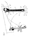
- the number 1 indicates an assembly to support a glass 2 (partially shown) for a motor vehicle door with an unframed upper edge (not shown), i.e. for a door without any upper structural element which delimits the window engaged by the glass 2.
- the assembly 1 is housed in a cavity 3 defined by a lower box portion 4 of the door (partially shown).
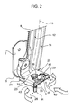
- the assembly 1 comprises a fixed support structure, of which only a bracket 5 is shown in the attached figures.
- the bracket 5 is L-shaped, is arranged at the lower end of the cavity 3, is fixed to the portion 4 in a way that is not shown, for example through use of screws, and comprises a lower horizontal plate 6 and an upper substantially vertical plate 7 that are connected to each other.
- the assembly 1 also comprises a frame defined by two elements 8,9, which are horizontally spaced from each other and carry a window-winding device 10 of a type that is known and is not described in detail.
- a window-winding device 10 of a type that is known and is not described in detail. The description that follows will only refer to the element 8, since the element 9 has substantially the same characteristics.
- the element 8 is defined by a plate, which is elongated in a vertical direction and is arched in such a way as to have a concave rear surface and a convex frontal surface 12.
- the surface 12 faces a lateral portion 13 of the glass 2 and carries, in a relative fixed position, a guide 14, which extends along a curved direction 15 parallel to the glass 2 and is slidingly engaged by a slide or runner 16.
- the runner 16 is fixed to the portion 13 in a way that is known and not described in detail, and is pulled along the guide 14 by the device 10 to slide between a raised position, in which the glass 2 closes the window of the door, and a lowered position (not shown), in which the glass 2 is housed in the cavity 3.
- the element 8 comprises an upper portion 18 linked to the portion 4 or to the fixed support structure through a coupling device (of a type that is known and is not shown), which is arranged on the rear surface of the element 8 and defines a hinge or a ball joint to make the element 8, the glass 2 and the device 10 tiltable about a substantially horizontal axis of adjustment 19 that is parallel to the glass 2 and orthogonal to the direction 15.
- a coupling device of a type that is known and is not shown
- the lower end of the element 8 is defined by a plate 20, which extends in a substantially horizontal direction towards the front in a cantilevered fashion, is superimposed on the plate 6, and is coupled with plate 6 in such a way as to be guided along a direction 22.
- the direction 22 is tangential with respect to the axis 19 and is parallel to the lateral edges 23 and 24 of the plates 20 and, respectively, 6.
- the edges 23 of the plate 20 are defined by respective tabs, which are folded downwards with respect to the plate 20, are arranged on opposing lateral sides of the plate and are slidingly coupled to the edges 24, which therefore guide the movement of the element 8.
- the plates 20 and 6 have, respectively, a round through-hole 25, with an axis 26 orthogonal to the direction 22, and a slot 27 elongated along the direction 22.
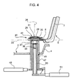
- the hole 25 and the slot 27 are aligned along the axis 26 and are engaged by a pin 28, which comprises an upper head 29 resting on the upper face of the plate 20 and a lower axial rod 30.
- the rod 30 comprises, in succession, a cylindrical upper end portion 31 ( Figure 2 ), an intermediate portion 32 with a quadrangular cross-section ( Figure 3 ), an intermediate threaded portion 33, and a lower end portion 34 with a hexagonal cross-section.
- the portion 31 is coupled to the internal edge of the hole 25, so that the pin 28 is axially rotatable, but arranged in a horizontal fixed position on the plate 20.
- the portion 33 has an outside diameter greater than that of the portion 34, extends with a clearance in the slot 27 and is therefore slidable along the direction 22, protrudes inferiorly with respect to the plate 6, and carries a screwed nut 36.
- a washer 37 is interposed between the nut 36 and the lower face of the plate 6. The nut 36 may be tightened to lock the pin 28 with respect to the plate 6 and, therefore, lock the position of the element 8 and the glass 2 about the axis 19.
- the assembly 1 comprises a positioning device 40 that converts the motion from rotational to translational to position the pin 28 along the slot 27 in response to a rotation of the pin 28 about the axis 26.
- the device 40 comprises a cam 41 defined by a spiral groove obtained for an angle of 180° about the axis 26 on a plate 42.
- the plate 42 rests on a plane orthogonal to the axis 26, is a piece that is separate in relation to the pin 28 and is arranged between the plates 20 and 6, and has a through-hole 43 that complements the portion 32 and is engaged by the portion 32, so that the cam 41 is fixed with respect to the pin 28.
- the device 40 also comprises a tappet 45 defined by a peg which is fixed to the plate 6, is arranged along the direction 22, and protrudes parallel to the axis 26 from the upper face of the plate 6 for a maximum height equal to the thickness of the plate 42, in such a way as to slidingly engage the cam 41.
- the nut 36 is loosened using a tubular hex key 47, which can be operated manually from outside the door using a lever 48 and is made to pass along the axis 26 in an opening 49 made in a lower side of the portion 4.
- the pin 28 can slide along the slot 27, even if it remains coupled to the plate 6 through the device 40.
- the portion 34 is rotated axially using a tubular adjustment key 50, which can be operated manually from outside the door using a lever 51 and is made to pass coaxially and inside the key 47.
- the cam 41 is made to rotate.
- the cam 41 defines a path with variable distance from the axis 26, so that the peg 45 is brought further away from or nearer to the axis 26.
- the relative movement between the axis 26 and the peg 45 causes the pin 28 to translate along the direction 22.
- the key 47 is turned to tighten the nut 36 maintaining the key 50 in a fixed position.
- the tightening of the nut 36 locks the plate 21 between the plates 20 and 6, so that the translation of the pin 28 is also blocked.
- the adjustment of the glass 2 about the axis 19 is simple and precise, since it is carried out by turning the pin 28 around its axis 26, without the need to act directly on the glass 2 or on the elements 8,9 of the frame, and without having to push or pull the pin 28 along the direction 22.
- the cam 41 has an angle of rotation proportional to the translation of the pin 28 and, by defining an arched path with a length greater than that of the slot 27, it expands the adjusting stroke in relation to the slot 27, so that positioning is carried out in a more precise manner than that of the prior art devoid of the device 40.
- the position chosen for the glass 2 following the adjustment is not changed by the operations to tighten the nut 36, since the pin 28 can be easily maintained in a fixed position along the slot 27 during such operations.
- the cam 41 could extend about the axis 26 by an angle other than of 180°; and/or the slot 27 and the peg 45 could be carried by the element 8 with the pin 28 carried by the bracket 5, in a dual manner with respect to the preferred solution described above; and/or the pin 28 could be parallel to the axis 19 (instead of being radial to the axis 19), with the plates 6 and 20 vertical (instead of horizontal).
- the portion 32 and the hole 43 could have only one flat side; or the plate 42 and the pin 28 could be fixed to each other, with the cam 41 possibly arranged externally with respect to the plates 20 and 6, instead of being locked between the plates 20 and 6.
- the assembly 1 could also be used for a rear window with an unframed upper edge, instead of for the glass of a side door.
Landscapes
- Window Of Vehicle (AREA)
- Power-Operated Mechanisms For Wings (AREA)
Priority Applications (4)
| Application Number | Priority Date | Filing Date | Title |
|---|---|---|---|
| ES08425105T ES2387251T3 (es) | 2008-02-21 | 2008-02-21 | Conjunto de soporte de vidrio para una puerta de vehículo a motor con un borde superior sin armazón |
| EP08425105A EP2093085B1 (de) | 2008-02-21 | 2008-02-21 | Glasstützbaueinheit für eine Kraftfahrzeugtür mit einer ungerahmten oberen Kante |
| BRPI0900699-0A BRPI0900699B1 (pt) | 2008-02-21 | 2009-02-13 | conjunto de suporte de vidro para uma porta de veículo automotor com uma borda superior sem caixilho |
| US12/388,985 US8091284B2 (en) | 2008-02-21 | 2009-02-19 | Glass supporting assembly for a motor vehicle door with an unframed upper edge |
Applications Claiming Priority (1)
| Application Number | Priority Date | Filing Date | Title |
|---|---|---|---|
| EP08425105A EP2093085B1 (de) | 2008-02-21 | 2008-02-21 | Glasstützbaueinheit für eine Kraftfahrzeugtür mit einer ungerahmten oberen Kante |
Publications (2)
| Publication Number | Publication Date |
|---|---|
| EP2093085A1 true EP2093085A1 (de) | 2009-08-26 |
| EP2093085B1 EP2093085B1 (de) | 2012-05-02 |
Family
ID=39543269
Family Applications (1)
| Application Number | Title | Priority Date | Filing Date |
|---|---|---|---|
| EP08425105A Not-in-force EP2093085B1 (de) | 2008-02-21 | 2008-02-21 | Glasstützbaueinheit für eine Kraftfahrzeugtür mit einer ungerahmten oberen Kante |
Country Status (4)
| Country | Link |
|---|---|
| US (1) | US8091284B2 (de) |
| EP (1) | EP2093085B1 (de) |
| BR (1) | BRPI0900699B1 (de) |
| ES (1) | ES2387251T3 (de) |
Cited By (2)
| Publication number | Priority date | Publication date | Assignee | Title |
|---|---|---|---|---|
| WO2012004151A1 (de) * | 2010-07-05 | 2012-01-12 | Brose Fahrzeugteile Gmbh & Co. Kg | Vorrichtung zum einstellen und arretieren der lage einer führungsschiene für eine verstellbare fensterscheibe in einer fahrzeugtür |
| CN104594747A (zh) * | 2014-12-03 | 2015-05-06 | 奇瑞汽车股份有限公司 | 一种玻璃升降器托架 |
Families Citing this family (6)
| Publication number | Priority date | Publication date | Assignee | Title |
|---|---|---|---|---|
| EP2447456B1 (de) * | 2010-11-02 | 2014-01-15 | Fiat Group Automobiles S.p.A. | Verfahren zur selbstanpassenden Registrierung der Position der Fensterscheibe einer Kraftfahrzeugtür mit rahmenlosem Fenster, sowie für dieses Verfahren vorgesehene Kraftfahrzeugtür |
| CN106697073A (zh) * | 2015-07-23 | 2017-05-24 | 北汽福田汽车股份有限公司 | 用于车辆的仪表板横梁组件及具有其的车辆 |
| US20190078366A1 (en) * | 2017-09-08 | 2019-03-14 | Magna Closures Inc. | Light weight two piece frameless door module with adjustment features |
| KR102575156B1 (ko) * | 2018-10-15 | 2023-09-06 | 현대자동차주식회사 | 위치조정이 가능한 도어 글래스 |
| US11319742B2 (en) * | 2018-10-18 | 2022-05-03 | Magna Closures Inc. | Door module with frameless glass configuration having adjustable glass run channels |
| KR102780835B1 (ko) * | 2022-07-20 | 2025-03-12 | 주식회사 광진 | 자동차용 윈도우 레귤레이터의 위치조정 구조 |
Citations (3)
| Publication number | Priority date | Publication date | Assignee | Title |
|---|---|---|---|---|
| US4956942A (en) * | 1989-06-09 | 1990-09-18 | Textron Inc. | Window adjustment mechanism |
| EP1520742A1 (de) * | 2003-10-03 | 2005-04-06 | Melchor Daumal Castellon | Vorrichtung zur Seiteneinstellung einer Fensterheberantriebsvorrichtung für Kraftfahrzeuge |
| FR2897587A1 (fr) * | 2006-02-22 | 2007-08-24 | Peugeot Citroen Automobiles Sa | Dispositif de montage articule d'une vitre sur une porte sans cadre de vehicule de type cabriolet ou coupe |
Family Cites Families (11)
| Publication number | Priority date | Publication date | Assignee | Title |
|---|---|---|---|---|
| JPH0613808B2 (ja) * | 1986-02-14 | 1994-02-23 | 株式会社大井製作所 | 自動車用窓ガラス開閉装置 |
| US5622005A (en) * | 1995-11-06 | 1997-04-22 | General Motors Corporation | Automotive door glass assembly |
| DE19819953A1 (de) * | 1998-05-05 | 1999-11-18 | Brose Fahrzeugteile | Einstellbarer Mitnehmer zur Anbindung einer Fensterscheibe an einen Fensterheber einer Kraftfahrzeugtür |
| US6426208B1 (en) * | 1999-11-12 | 2002-07-30 | Harbor-Ucla Research And Education Institute | Recombinant α-L-iduronidase, methods for producing and purifying the same and methods for treating diseases caused by deficiencies thereof |
| US6283534B1 (en) * | 2000-07-24 | 2001-09-04 | The Budd Company | Active door upper |
| US6598345B1 (en) * | 2001-08-22 | 2003-07-29 | Hi-Lex Corporation | Window regulator having a cam member for lateral adjustment |
| US7640697B2 (en) * | 2002-10-30 | 2010-01-05 | Brose Fahrzeugteile Gmbh & Co. Kg, Coburg | Device for connecting the fixing region of a guide rail to the door body of a vehicle door |
| DE20310038U1 (de) * | 2003-06-25 | 2004-11-04 | Brose Fahrzeugteile Gmbh & Co. Kg, Coburg | Umlenkeinrichtung für einen Kraftfahrzeugfensterheber |
| FR2897597A1 (fr) | 2006-02-20 | 2007-08-24 | Karim Saada | Enveloppe contenant une zone predecoupee pour son ouverture |
| DE102006012176A1 (de) * | 2006-03-16 | 2007-09-20 | Lisa Dräxlmaier GmbH | Einstellbarer Fensterheber I |
| IT1396529B1 (it) * | 2008-05-26 | 2012-05-25 | Magna Closures Spa | Meccanismo per regolare la posizione di montaggio di un alzacristalli |
-
2008
- 2008-02-21 ES ES08425105T patent/ES2387251T3/es active Active
- 2008-02-21 EP EP08425105A patent/EP2093085B1/de not_active Not-in-force
-
2009
- 2009-02-13 BR BRPI0900699-0A patent/BRPI0900699B1/pt not_active IP Right Cessation
- 2009-02-19 US US12/388,985 patent/US8091284B2/en active Active
Patent Citations (3)
| Publication number | Priority date | Publication date | Assignee | Title |
|---|---|---|---|---|
| US4956942A (en) * | 1989-06-09 | 1990-09-18 | Textron Inc. | Window adjustment mechanism |
| EP1520742A1 (de) * | 2003-10-03 | 2005-04-06 | Melchor Daumal Castellon | Vorrichtung zur Seiteneinstellung einer Fensterheberantriebsvorrichtung für Kraftfahrzeuge |
| FR2897587A1 (fr) * | 2006-02-22 | 2007-08-24 | Peugeot Citroen Automobiles Sa | Dispositif de montage articule d'une vitre sur une porte sans cadre de vehicule de type cabriolet ou coupe |
Cited By (3)
| Publication number | Priority date | Publication date | Assignee | Title |
|---|---|---|---|---|
| WO2012004151A1 (de) * | 2010-07-05 | 2012-01-12 | Brose Fahrzeugteile Gmbh & Co. Kg | Vorrichtung zum einstellen und arretieren der lage einer führungsschiene für eine verstellbare fensterscheibe in einer fahrzeugtür |
| US8646209B2 (en) | 2010-07-05 | 2014-02-11 | Brose Fahrzeugteile Gmbh & Co. Kg | Device for adjusting and locking the position of a guide rail for a movable windowpane in a vehicle door |
| CN104594747A (zh) * | 2014-12-03 | 2015-05-06 | 奇瑞汽车股份有限公司 | 一种玻璃升降器托架 |
Also Published As
| Publication number | Publication date |
|---|---|
| US20090211159A1 (en) | 2009-08-27 |
| US8091284B2 (en) | 2012-01-10 |
| BRPI0900699B1 (pt) | 2020-04-14 |
| ES2387251T3 (es) | 2012-09-19 |
| BRPI0900699A2 (pt) | 2010-01-19 |
| EP2093085B1 (de) | 2012-05-02 |
Similar Documents
| Publication | Publication Date | Title |
|---|---|---|
| US8091284B2 (en) | Glass supporting assembly for a motor vehicle door with an unframed upper edge | |
| AU2008340578B2 (en) | Front-adjustment means for drawers, and drawer | |
| US8336972B2 (en) | Displacement device for pivotally held separation elements and article of furniture | |
| US20220259909A1 (en) | Fitting Arrangement | |
| US9546509B2 (en) | Hinge | |
| US8646209B2 (en) | Device for adjusting and locking the position of a guide rail for a movable windowpane in a vehicle door | |
| US8707517B2 (en) | Hinge for a folding door | |
| US7971319B2 (en) | Hinge for doors or windows | |
| US11585115B2 (en) | Small-angle latch system for a lock | |
| US20090229076A1 (en) | Absorption mechanism for furniture doors | |
| EP3757322B1 (de) | Einstellbares verdecktes scharnier | |
| CA3020835C (en) | End load arm | |
| US10323447B2 (en) | Adjustable guide device for a sliding element | |
| HU222364B1 (hu) | Tetõablak | |
| EP1722057A2 (de) | Verstellbare Unterstützungsvorrichtung für Tür- und Fensterscharniere | |
| CN117287091B (zh) | 一种中心距可调传动壳及门窗结构 | |
| WO2012109403A1 (en) | Adjustable gate mounting hinge | |
| EP3080372A1 (de) | Fahrzeugtürscharnier | |
| TH17261Y (th) | ชุดอุปกรณ์ช่วยในการเปิด-ปิดบานหน้าต่างหรือบานประตู | |
| EP2899352B1 (de) | Justierbare trägereinheit zum aufhängen von raumgliederungselementen | |
| JP2000352264A (ja) | ウインドレギュレータのウインドパネル姿勢調整装置 | |
| CN106460429A (zh) | 用于窗或门的可移置的翼扇的包括滑槽的可调节的竖直加强装置 | |
| NZ740545B2 (en) | Adjustable guide device for a sliding element | |
| JP2016199991A (ja) | ドアクローザ | |
| GB2045330A (en) | Multiple Fastenings |
Legal Events
| Date | Code | Title | Description |
|---|---|---|---|
| PUAI | Public reference made under article 153(3) epc to a published international application that has entered the european phase |
Free format text: ORIGINAL CODE: 0009012 |
|
| AK | Designated contracting states |
Kind code of ref document: A1 Designated state(s): AT BE BG CH CY CZ DE DK EE ES FI FR GB GR HR HU IE IS IT LI LT LU LV MC MT NL NO PL PT RO SE SI SK TR |
|
| AX | Request for extension of the european patent |
Extension state: AL BA MK RS |
|
| 17P | Request for examination filed |
Effective date: 20100225 |
|
| AKX | Designation fees paid |
Designated state(s): DE ES FR GB IT TR |
|
| 17Q | First examination report despatched |
Effective date: 20110118 |
|
| GRAP | Despatch of communication of intention to grant a patent |
Free format text: ORIGINAL CODE: EPIDOSNIGR1 |
|
| GRAS | Grant fee paid |
Free format text: ORIGINAL CODE: EPIDOSNIGR3 |
|
| GRAA | (expected) grant |
Free format text: ORIGINAL CODE: 0009210 |
|
| AK | Designated contracting states |
Kind code of ref document: B1 Designated state(s): DE ES FR GB IT TR |
|
| REG | Reference to a national code |
Ref country code: GB Ref legal event code: FG4D |
|
| RIN1 | Information on inventor provided before grant (corrected) |
Inventor name: IENNARELLA, VINCENZO,C/O FIAT GROUP AUTOMOBILES S. Inventor name: MACOR, ALESSANDRO,C/O FIAT AUTOMOBILES S.P.A. |
|
| RIN2 | Information on inventor provided after grant (corrected) |
Inventor name: MACOR, ALESSANDRO,C/O FIAT GROUP AUTOMOBILES S.P.A Inventor name: IENNARELLA, VINCENZO,C/O FIAT GROUP AUTOMOBILES S. |
|
| REG | Reference to a national code |
Ref country code: DE Ref legal event code: R096 Ref document number: 602008015347 Country of ref document: DE Effective date: 20120705 |
|
| REG | Reference to a national code |
Ref country code: ES Ref legal event code: FG2A Ref document number: 2387251 Country of ref document: ES Kind code of ref document: T3 Effective date: 20120919 |
|
| PLBE | No opposition filed within time limit |
Free format text: ORIGINAL CODE: 0009261 |
|
| STAA | Information on the status of an ep patent application or granted ep patent |
Free format text: STATUS: NO OPPOSITION FILED WITHIN TIME LIMIT |
|
| 26N | No opposition filed |
Effective date: 20130205 |
|
| PGFP | Annual fee paid to national office [announced via postgrant information from national office to epo] |
Ref country code: GB Payment date: 20130220 Year of fee payment: 6 Ref country code: ES Payment date: 20130215 Year of fee payment: 6 |
|
| REG | Reference to a national code |
Ref country code: DE Ref legal event code: R097 Ref document number: 602008015347 Country of ref document: DE Effective date: 20130205 |
|
| GBPC | Gb: european patent ceased through non-payment of renewal fee |
Effective date: 20140221 |
|
| PG25 | Lapsed in a contracting state [announced via postgrant information from national office to epo] |
Ref country code: GB Free format text: LAPSE BECAUSE OF NON-PAYMENT OF DUE FEES Effective date: 20140221 |
|
| REG | Reference to a national code |
Ref country code: ES Ref legal event code: FD2A Effective date: 20150327 |
|
| PG25 | Lapsed in a contracting state [announced via postgrant information from national office to epo] |
Ref country code: ES Free format text: LAPSE BECAUSE OF NON-PAYMENT OF DUE FEES Effective date: 20140222 |
|
| REG | Reference to a national code |
Ref country code: FR Ref legal event code: PLFP Year of fee payment: 9 |
|
| REG | Reference to a national code |
Ref country code: FR Ref legal event code: PLFP Year of fee payment: 10 |
|
| PG25 | Lapsed in a contracting state [announced via postgrant information from national office to epo] |
Ref country code: TR Free format text: LAPSE BECAUSE OF NON-PAYMENT OF DUE FEES Effective date: 20140221 |
|
| REG | Reference to a national code |
Ref country code: FR Ref legal event code: PLFP Year of fee payment: 11 |
|
| PGFP | Annual fee paid to national office [announced via postgrant information from national office to epo] |
Ref country code: DE Payment date: 20240123 Year of fee payment: 17 |
|
| PGFP | Annual fee paid to national office [announced via postgrant information from national office to epo] |
Ref country code: IT Payment date: 20240123 Year of fee payment: 17 Ref country code: FR Payment date: 20240123 Year of fee payment: 17 |
|
| REG | Reference to a national code |
Ref country code: DE Ref legal event code: R119 Ref document number: 602008015347 Country of ref document: DE |
|
| PG25 | Lapsed in a contracting state [announced via postgrant information from national office to epo] |
Ref country code: DE Free format text: LAPSE BECAUSE OF NON-PAYMENT OF DUE FEES Effective date: 20250902 |
|
| PG25 | Lapsed in a contracting state [announced via postgrant information from national office to epo] |
Ref country code: FR Free format text: LAPSE BECAUSE OF NON-PAYMENT OF DUE FEES Effective date: 20250228 Ref country code: IT Free format text: LAPSE BECAUSE OF NON-PAYMENT OF DUE FEES Effective date: 20250221 |