EP2093383A1 - Leitschaufel und Leitschaufelanordnung - Google Patents
Leitschaufel und Leitschaufelanordnung Download PDFInfo
- Publication number
- EP2093383A1 EP2093383A1 EP08254064A EP08254064A EP2093383A1 EP 2093383 A1 EP2093383 A1 EP 2093383A1 EP 08254064 A EP08254064 A EP 08254064A EP 08254064 A EP08254064 A EP 08254064A EP 2093383 A1 EP2093383 A1 EP 2093383A1
- Authority
- EP
- European Patent Office
- Prior art keywords
- vane
- platform
- circumferential extension
- flange
- airfoil portion
- Prior art date
- Legal status (The legal status is an assumption and is not a legal conclusion. Google has not performed a legal analysis and makes no representation as to the accuracy of the status listed.)
- Granted
Links
Images



Classifications
-
- F—MECHANICAL ENGINEERING; LIGHTING; HEATING; WEAPONS; BLASTING
- F01—MACHINES OR ENGINES IN GENERAL; ENGINE PLANTS IN GENERAL; STEAM ENGINES
- F01D—NON-POSITIVE DISPLACEMENT MACHINES OR ENGINES, e.g. STEAM TURBINES
- F01D9/00—Stators
- F01D9/02—Nozzles; Nozzle boxes; Stator blades; Guide conduits, e.g. individual nozzles
- F01D9/04—Nozzles; Nozzle boxes; Stator blades; Guide conduits, e.g. individual nozzles forming ring or sector
- F01D9/042—Nozzles; Nozzle boxes; Stator blades; Guide conduits, e.g. individual nozzles forming ring or sector fixing blades to stators
-
- F—MECHANICAL ENGINEERING; LIGHTING; HEATING; WEAPONS; BLASTING
- F01—MACHINES OR ENGINES IN GENERAL; ENGINE PLANTS IN GENERAL; STEAM ENGINES
- F01D—NON-POSITIVE DISPLACEMENT MACHINES OR ENGINES, e.g. STEAM TURBINES
- F01D25/00—Component parts, details, or accessories, not provided for in, or of interest apart from, other groups
- F01D25/16—Arrangement of bearings; Supporting or mounting bearings in casings
- F01D25/162—Bearing supports
-
- F—MECHANICAL ENGINEERING; LIGHTING; HEATING; WEAPONS; BLASTING
- F01—MACHINES OR ENGINES IN GENERAL; ENGINE PLANTS IN GENERAL; STEAM ENGINES
- F01D—NON-POSITIVE DISPLACEMENT MACHINES OR ENGINES, e.g. STEAM TURBINES
- F01D25/00—Component parts, details, or accessories, not provided for in, or of interest apart from, other groups
- F01D25/24—Casings; Casing parts, e.g. diaphragms, casing fastenings
- F01D25/246—Fastening of diaphragms or stator-rings
Definitions
- the present invention relates to vanes and vane assemblies for use with gas turbine engines.
- the amount of space available for securing the platforms of the vane details is limited, particularly at the inner shroud.
- the vane detail platforms have been positioned next to each other in close proximity in a nested configuration.
- known nested designs are not readily scaled to allow any number of vanes within a given vane assembly in an engine, but rather face maximum vane count limits.
- the present invention provides an alternative vane and vane assembly configuration that allows for relatively high vane counts.
- a vane assembly includes a plurality of vanes with the first circumferential extension of one vane engaging the second circumferential extension of an adjacent vane to define a shiplap joint.
- FIG. 1 is a schematic cross-sectional view of an exemplary two-spool gas turbine engine 20.
- the engine 20 includes a fan 22, a low-pressure compressor (LPC) section 24, a high-pressure compressor (HPC) section 26, a combustor assembly 28, a high-pressure turbine (HPT) section 30, and a low-pressure turbine (LPT) section 34 all arranged about an engine centerline C L .
- LPC low-pressure compressor
- HPC high-pressure compressor
- HPT high-pressure turbine
- LPT low-pressure turbine
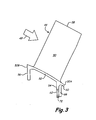
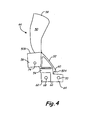
- FIGS. 3-5 illustrate one vane 44 for use with the LPC exit guide vane assembly 40.
- FIG. 3 is a side view of the vane 44
- FIG. 4 is a front view of the vane 44
- FIG. 5 is an isometric view of the vane 44.
- the vane 44 includes an airfoil portion 50, a platform 52, a first flange 54 and a second flange 56.
- Each vane can be made of metallic materials such as titanium, nickel, cobalt, aluminum, etc. and alloys containing such metals.
- the vanes 44 can be fabricated using known processes such as casting, forging, machining, etc. Coatings (not specifically shown) can be applied to portions of the vanes 44 as desired.
- the platform 52 is arranged at an opposite end of the airfoil portion 50 from the free end 58, and can have a parallelogram-shaped profile.
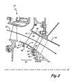
- the platform 52 can be positioned radially inward in the LPC exit guide vane assembly 40, as shown in FIG. 2 , to define a segment of an inner diameter (ID) boundary of the primary flowpath 49.
- the airfoil portion 50 is integrally formed with platform 52.
- the platform 52 can define a lip 60 at a downstream edge 52A to provide sealing or other functionality, as explained further below.
- the first and second flanges 54 and 56 both extend from the platform 52 away from the airfoil portion 50, that is, in a radially inward direction.
- the first and second flanges 54 and 56 can both be configured to be substantially perpendicular to the engine centerline C L when the vane 44 is installed in the LPC exit guide vane assembly 40 of the engine 20.
- the first flange 54 is arranged adjacent to the lip 60 at the downstream edge 52A of the platform 52, and can be integrally formed with the platform 52.
- the first flange 54 includes a first circumferential extension 62 and a second circumferential extension (or lobe) 64.
- the first and second circumferential extensions 62 and 64 meet at a central portion 66.
- Openings 68 and 70 are located in the first and second circumferential extensions 62 and 64, respectively, which enable the first flange 54 to be secured to the downstream ring 48 with suitable fasteners, such as rivets (see FIGS. 2 and 7 ).
- a cutaway portion is defined in the first flange 54 at a forward face of the first circumferential extension 62.
- the cutaway portion at the first circumferential extension 62 has a shape that corresponds to that of the second circumferential extension 64.
- the cutaway portion extends to a radially inward edge of the first circumferential extension 62 but its radially outward extent does not reach the platform 52.
- a depth of the cutaway portion (measured in the axial direction) at the first circumferential extension 62 can be at least as great as a thickness of the second circumferential extension 64 (measured in the axial direction), with a thickness of the central portion 66 being equal to a total distance between an aft face of the first circumferential extension 62 and a forward face of the second circumferential extension 64.
- the first flange 54 is configured to form a shiplap joint when engaged with an adjacent vane 44 of similar configuration, as explained further below.
- the first and second circumferential extensions 62 and 64 are axially offset, such that the forward face of the first circumferential extension 62 within the cutaway portion is substantially axially aligned (i.e., co-planar) with the aft face of the second circumferential extension 64.
- FIG. 6 is a perspective view of the LPC exit guide vane assembly 40 during assembly, and prior to installation in the engine 20, and
- FIG. 7 is an enlarged perspective view of a portion of the LPC exit guide vane assembly 40 at region VII of FIG. 6 .
- a plurality of the vanes 44 (only some of the vanes 44 are labeled in FIG. 6 for simplicity) are positioned adjacent one another in a cascade configuration, with the airfoil portions 50 spanning an annular gap between the integral platform segments 52 (at the ID flowpath boundary) and the OD shroud ring 42.
- adjacent vanes 44 may need to be at least partially unseated relative to the downstream ring 48 while the last vane 44 is wiggled into position and the adjacent vanes 44 reseated against the downstream ring 48.
- the "free" ends (or tips) 58 of the vanes 44 are inserted into slots in the OD shroud ring 42 and potted using a conformable material such as rubber.
- Temporary fasteners 76 are used to secure the second flange 56 (not visible in FIG. 6 ) of each vane 44 to the upstream ring 46. The temporary fasteners 76 are systematically removed and replaced by rivets 78 during the assembly process.
- Rivets 78 are also used to secure the first flange 54 to the downstream ring 48.
- a sealant e.g., rubber sealant
- a sealant can be applied between the platforms 52 of adjacent vanes 44, to help reduce fluid leakage at the ID boundary of the primary flowpath 49.
- the configuration of the shiplap joint in the illustrated embodiment, with the first circumferential extension 62 offset so as to be positioned generally aft of the second circumferential extension 64, can help reduce tensile stress in the rivets 78.
- operational loading on the airfoil portion 50 will tend to cause the first circumferential extension 62 to pull away from the downstream ring 48 and the second circumferential extension 64 (located at a suction side of the airfoil portion 50, as best shown in FIG. 5 ) to push toward the downstream ring 48.
- the illustrated embodiment of the shiplap joint causes the operational loads transmitted through the second circumferential extensions 64 to offset those transmitted through the first circumferential extensions 62, thereby helping to lessen overall tensile loading on the rivets 78.
- the vanes 44 of the LPC exit guide vane assembly 40 require repair or replacement, it is possible to remove the rivets 78 (or other fasteners) attaching the selected vane 44 and adjacent vanes 44.
- the selected vane 44 can be removed or replaced, and then the LPC exit guide vane assembly 40 reassembled in the manner described above with regard to the installation of the last vane in the assembly.
Landscapes
- Engineering & Computer Science (AREA)
- Mechanical Engineering (AREA)
- General Engineering & Computer Science (AREA)
- Turbine Rotor Nozzle Sealing (AREA)
- Structures Of Non-Positive Displacement Pumps (AREA)
Applications Claiming Priority (1)
| Application Number | Priority Date | Filing Date | Title |
|---|---|---|---|
| US12/070,466 US8511983B2 (en) | 2008-02-19 | 2008-02-19 | LPC exit guide vane and assembly |
Publications (2)
| Publication Number | Publication Date |
|---|---|
| EP2093383A1 true EP2093383A1 (de) | 2009-08-26 |
| EP2093383B1 EP2093383B1 (de) | 2011-03-23 |
Family
ID=40750767
Family Applications (1)
| Application Number | Title | Priority Date | Filing Date |
|---|---|---|---|
| EP08254064A Ceased EP2093383B1 (de) | 2008-02-19 | 2008-12-18 | Leitschaufel und Leitschaufelanordnung |
Country Status (3)
| Country | Link |
|---|---|
| US (1) | US8511983B2 (de) |
| EP (1) | EP2093383B1 (de) |
| DE (1) | DE602008005705D1 (de) |
Cited By (7)
| Publication number | Priority date | Publication date | Assignee | Title |
|---|---|---|---|---|
| EP2295724A1 (de) * | 2009-08-28 | 2011-03-16 | Siemens Aktiengesellschaft | Leitschaufel für eine axial durchströmbare Turbomaschine und zugehörige Leitschaufelanordnung |
| CH704140A1 (de) * | 2010-11-29 | 2012-05-31 | Alstom Technology Ltd | Schaufelanordnung für eine rotierende Strömungsmaschine. |
| FR2983247A1 (fr) * | 2011-11-29 | 2013-05-31 | Snecma | Ensemble redresseur - carter intermediaire pour une turbomachine |
| US9447693B2 (en) | 2012-07-30 | 2016-09-20 | United Technologies Corporation | Compliant assembly |
| FR3115321A1 (fr) * | 2020-10-20 | 2022-04-22 | Safran Aircraft Engines | étage de redressement d’un flux d’air pour une turbomachine |
| WO2022167373A1 (fr) | 2021-02-02 | 2022-08-11 | Safran Aero Boosters | Ensemble redresseur pour compresseur de turbomachine d'aeronef |
| EP4105446A1 (de) * | 2021-06-18 | 2022-12-21 | Rolls-Royce plc | Leitschaufelbefestigungsanordnung |
Families Citing this family (16)
| Publication number | Priority date | Publication date | Assignee | Title |
|---|---|---|---|---|
| US8002515B2 (en) * | 2008-09-08 | 2011-08-23 | General Electric Company | Flow inhibitor of turbomachine shroud |
| US8966755B2 (en) | 2011-01-20 | 2015-03-03 | United Technologies Corporation | Assembly fixture for a stator vane assembly |
| US8966756B2 (en) * | 2011-01-20 | 2015-03-03 | United Technologies Corporation | Gas turbine engine stator vane assembly |
| US8834109B2 (en) * | 2011-08-03 | 2014-09-16 | United Technologies Corporation | Vane assembly for a gas turbine engine |
| PL2739861T3 (pl) * | 2011-08-04 | 2020-01-31 | Novenco Building & Industry A/S | Dmuchawa osiowa |
| EP2859189B1 (de) * | 2012-05-30 | 2017-12-27 | United Technologies Corporation | Montagearmatur für leitschaufelanordnung |
| US9045985B2 (en) * | 2012-05-31 | 2015-06-02 | United Technologies Corporation | Stator vane bumper ring |
| WO2014138147A2 (en) * | 2013-03-07 | 2014-09-12 | United Technologies Corporation | Structural guide vane for gas turbine engine |
| US20150267610A1 (en) * | 2013-03-13 | 2015-09-24 | United Technologies Corporation | Turbine enigne including balanced low pressure stage count |
| US20140290211A1 (en) * | 2013-03-13 | 2014-10-02 | United Technologies Corporation | Turbine engine including balanced low pressure stage count |
| US20150013301A1 (en) * | 2013-03-13 | 2015-01-15 | United Technologies Corporation | Turbine engine including balanced low pressure stage count |
| EP2971606A4 (de) * | 2013-03-15 | 2016-12-28 | United Technologies Corp | Verstärktes verbundgehäuse |
| EP3027855B1 (de) * | 2013-07-30 | 2020-09-09 | United Technologies Corporation | Gasturbinentriebwerk mit einer leitschaufelringanordnung |
| BE1022361B1 (fr) * | 2014-11-06 | 2016-03-17 | Techspace Aero Sa | Stator mixte de compresseur de turbomachine axiale. |
| FR3134598B1 (fr) * | 2022-04-15 | 2024-04-05 | Safran Aircraft Engines | Aube fixe en matériaux composites fixée radialement sur une structure fixe d’une turbomachine |
| US20240309810A1 (en) * | 2023-03-14 | 2024-09-19 | Raytheon Technologies Corporation | Introducing steam into core air upstream of turbine engine diffuser plenum |
Citations (2)
| Publication number | Priority date | Publication date | Assignee | Title |
|---|---|---|---|---|
| US20030185673A1 (en) * | 2002-01-21 | 2003-10-02 | Honda Giken Kogyo Kabushiki Kaisha | Flow-rectifying member and its unit and method for producing flow-rectifying member |
| EP1596036A1 (de) * | 2004-05-14 | 2005-11-16 | General Electric Company | Reibrührgeschweisste Hohlschaufeln und entsprechendes Verfahren |
Family Cites Families (16)
| Publication number | Priority date | Publication date | Assignee | Title |
|---|---|---|---|---|
| US2632397A (en) | 1949-02-10 | 1953-03-24 | Chrysler Corp | Rotor wheel |
| GB678085A (en) * | 1949-02-15 | 1952-08-27 | Rolls Royce | Improvements in or relating to compressors and turbines |
| US3351319A (en) | 1966-09-01 | 1967-11-07 | United Aircraft Corp | Compressor and fan exit guide vane assembly |
| CH482915A (de) * | 1967-11-03 | 1969-12-15 | Sulzer Ag | Leitvorrichtung für Axialturbine |
| US4832568A (en) | 1982-02-26 | 1989-05-23 | General Electric Company | Turbomachine airfoil mounting assembly |
| US4492517A (en) * | 1983-01-06 | 1985-01-08 | General Electric Company | Segmented inlet nozzle for gas turbine, and methods of installation |
| FR2600379B1 (fr) | 1986-06-18 | 1988-09-02 | Snecma | Redresseur de soufflante de turboreacteur multiflux |
| US4827588A (en) | 1988-01-04 | 1989-05-09 | Williams International Corporation | Method of making a turbine nozzle |
| US5441385A (en) * | 1993-12-13 | 1995-08-15 | Solar Turbines Incorporated | Turbine nozzle/nozzle support structure |
| US5411370A (en) | 1994-08-01 | 1995-05-02 | United Technologies Corporation | Vibration damping shroud for a turbomachine vane |
| US6543995B1 (en) | 1999-08-09 | 2003-04-08 | United Technologies Corporation | Stator vane and stator assembly for a rotary machine |
| US6409472B1 (en) | 1999-08-09 | 2002-06-25 | United Technologies Corporation | Stator assembly for a rotary machine and clip member for a stator assembly |
| US6343912B1 (en) | 1999-12-07 | 2002-02-05 | General Electric Company | Gas turbine or jet engine stator vane frame |
| US6932568B2 (en) | 2003-02-27 | 2005-08-23 | General Electric Company | Turbine nozzle segment cantilevered mount |
| GB0505978D0 (en) * | 2005-03-24 | 2005-04-27 | Alstom Technology Ltd | Interlocking turbine blades |
| US7481618B2 (en) | 2005-12-21 | 2009-01-27 | Rolls-Royce Plc | Mounting arrangement |
-
2008
- 2008-02-19 US US12/070,466 patent/US8511983B2/en active Active
- 2008-12-18 EP EP08254064A patent/EP2093383B1/de not_active Ceased
- 2008-12-18 DE DE602008005705T patent/DE602008005705D1/de active Active
Patent Citations (2)
| Publication number | Priority date | Publication date | Assignee | Title |
|---|---|---|---|---|
| US20030185673A1 (en) * | 2002-01-21 | 2003-10-02 | Honda Giken Kogyo Kabushiki Kaisha | Flow-rectifying member and its unit and method for producing flow-rectifying member |
| EP1596036A1 (de) * | 2004-05-14 | 2005-11-16 | General Electric Company | Reibrührgeschweisste Hohlschaufeln und entsprechendes Verfahren |
Cited By (13)
| Publication number | Priority date | Publication date | Assignee | Title |
|---|---|---|---|---|
| EP2295724A1 (de) * | 2009-08-28 | 2011-03-16 | Siemens Aktiengesellschaft | Leitschaufel für eine axial durchströmbare Turbomaschine und zugehörige Leitschaufelanordnung |
| US8622708B2 (en) | 2009-08-28 | 2014-01-07 | Siemens Aktiengesellschaft | Stator blade for a turbomachine which is exposable to axial throughflow, and also stator blade arrangement for it |
| CH704140A1 (de) * | 2010-11-29 | 2012-05-31 | Alstom Technology Ltd | Schaufelanordnung für eine rotierende Strömungsmaschine. |
| FR2983247A1 (fr) * | 2011-11-29 | 2013-05-31 | Snecma | Ensemble redresseur - carter intermediaire pour une turbomachine |
| US9447693B2 (en) | 2012-07-30 | 2016-09-20 | United Technologies Corporation | Compliant assembly |
| WO2022084634A1 (fr) * | 2020-10-20 | 2022-04-28 | Safran Aircraft Engines | Turbomachine comprenant un tel ensemble |
| FR3115321A1 (fr) * | 2020-10-20 | 2022-04-22 | Safran Aircraft Engines | étage de redressement d’un flux d’air pour une turbomachine |
| US12071865B2 (en) | 2020-10-20 | 2024-08-27 | Safran Aircraft Engines | Air flow straightening stage for a turbomachine |
| WO2022167373A1 (fr) | 2021-02-02 | 2022-08-11 | Safran Aero Boosters | Ensemble redresseur pour compresseur de turbomachine d'aeronef |
| BE1029074B1 (fr) * | 2021-02-02 | 2022-08-29 | Safran Aero Boosters | Ensemble redresseur pour compresseur de turbomachine d'aeronef |
| US12320275B2 (en) | 2021-02-02 | 2025-06-03 | Safran Aero Boosters | Stator vane assembly for an aircraft turbine engine compressor |
| EP4105446A1 (de) * | 2021-06-18 | 2022-12-21 | Rolls-Royce plc | Leitschaufelbefestigungsanordnung |
| US11828198B2 (en) | 2021-06-18 | 2023-11-28 | Rolls-Royce Plc | Vane joint |
Also Published As
| Publication number | Publication date |
|---|---|
| US20090208332A1 (en) | 2009-08-20 |
| DE602008005705D1 (de) | 2011-05-05 |
| EP2093383B1 (de) | 2011-03-23 |
| US8511983B2 (en) | 2013-08-20 |
Similar Documents
| Publication | Publication Date | Title |
|---|---|---|
| US8511983B2 (en) | LPC exit guide vane and assembly | |
| EP3022394B1 (de) | Turbinendüse mit einer prallplatte | |
| EP2204539B1 (de) | Statoranordnung für einen Gasturbinenmotor | |
| EP2620591B1 (de) | Leitschaufelanordnung für Gasturbinentriebwerk mit innerem Abdeckring | |
| EP3147461A1 (de) | Elastische ringdichtung für einen gasturbinenmotor und zugehörige dichtungsanordnung | |
| US9222363B2 (en) | Angular sector of a stator for a turbine engine compressor, a turbine engine stator, and a turbine engine including such a sector | |
| NL2006077C2 (en) | Turbine shroud mounting apparatus with anti-rotation feature. | |
| US9784116B2 (en) | Turbine shroud assembly | |
| EP2568121A1 (de) | Konischer stufenformiger Dichtmaterialträger und zugehörige ringförmige Dichtung | |
| EP2615256B1 (de) | T-federdichtung einer gasturbine | |
| CN108691810B (zh) | 涡轮发动机容纳组件及其制造方法 | |
| US20130333350A1 (en) | Airfoil including adhesively bonded shroud | |
| EP2855898B1 (de) | Statorschaufel-stossfängerring | |
| US11473437B2 (en) | Turbine snap in spring seal | |
| WO2013169442A1 (en) | Stator assembly | |
| EP2855896B1 (de) | Fehlervermeidung für statorschaufel | |
| US9068475B2 (en) | Stator vane assembly | |
| EP3712381B1 (de) | Innendeckbandanordnung für leitschaufeln | |
| CN112539087B (zh) | 弹簧密封件中的涡轮卡扣 | |
| US10738638B2 (en) | Rotor blade with wheel space swirlers and method for forming a rotor blade with wheel space swirlers | |
| US11480061B2 (en) | Method for replacing metal airfoil with ceramic airfoil, and related turbomachine blade | |
| US11035238B2 (en) | Airfoil including adhesively bonded shroud | |
| US8690530B2 (en) | System and method for supporting a nozzle assembly | |
| US20260002447A1 (en) | Stator vane segment |
Legal Events
| Date | Code | Title | Description |
|---|---|---|---|
| PUAI | Public reference made under article 153(3) epc to a published international application that has entered the european phase |
Free format text: ORIGINAL CODE: 0009012 |
|
| AK | Designated contracting states |
Kind code of ref document: A1 Designated state(s): AT BE BG CH CY CZ DE DK EE ES FI FR GB GR HR HU IE IS IT LI LT LU LV MC MT NL NO PL PT RO SE SI SK TR |
|
| AX | Request for extension of the european patent |
Extension state: AL BA MK RS |
|
| 17P | Request for examination filed |
Effective date: 20090928 |
|
| 17Q | First examination report despatched |
Effective date: 20091117 |
|
| AKX | Designation fees paid |
Designated state(s): DE GB |
|
| GRAP | Despatch of communication of intention to grant a patent |
Free format text: ORIGINAL CODE: EPIDOSNIGR1 |
|
| GRAS | Grant fee paid |
Free format text: ORIGINAL CODE: EPIDOSNIGR3 |
|
| GRAA | (expected) grant |
Free format text: ORIGINAL CODE: 0009210 |
|
| AK | Designated contracting states |
Kind code of ref document: B1 Designated state(s): DE GB |
|
| REG | Reference to a national code |
Ref country code: GB Ref legal event code: FG4D |
|
| REF | Corresponds to: |
Ref document number: 602008005705 Country of ref document: DE Date of ref document: 20110505 Kind code of ref document: P |
|
| REG | Reference to a national code |
Ref country code: DE Ref legal event code: R096 Ref document number: 602008005705 Country of ref document: DE Effective date: 20110505 |
|
| PLBE | No opposition filed within time limit |
Free format text: ORIGINAL CODE: 0009261 |
|
| STAA | Information on the status of an ep patent application or granted ep patent |
Free format text: STATUS: NO OPPOSITION FILED WITHIN TIME LIMIT |
|
| 26N | No opposition filed |
Effective date: 20111227 |
|
| REG | Reference to a national code |
Ref country code: DE Ref legal event code: R097 Ref document number: 602008005705 Country of ref document: DE Effective date: 20111227 |
|
| REG | Reference to a national code |
Ref country code: DE Ref legal event code: R082 Ref document number: 602008005705 Country of ref document: DE Representative=s name: SCHMITT-NILSON SCHRAUD WAIBEL WOHLFROM PATENTA, DE |
|
| REG | Reference to a national code |
Ref country code: DE Ref legal event code: R082 Ref document number: 602008005705 Country of ref document: DE Representative=s name: SCHMITT-NILSON SCHRAUD WAIBEL WOHLFROM PATENTA, DE Ref country code: DE Ref legal event code: R081 Ref document number: 602008005705 Country of ref document: DE Owner name: UNITED TECHNOLOGIES CORP. (N.D.GES.D. STAATES , US Free format text: FORMER OWNER: UNITED TECHNOLOGIES CORPORATION, HARTFORD, CONN., US |
|
| REG | Reference to a national code |
Ref country code: DE Ref legal event code: R081 Ref document number: 602008005705 Country of ref document: DE Owner name: RAYTHEON TECHNOLOGIES CORPORATION (N.D.GES.D.S, US Free format text: FORMER OWNER: UNITED TECHNOLOGIES CORP. (N.D.GES.D. STAATES DELAWARE), FARMINGTON, CONN., US |
|
| P01 | Opt-out of the competence of the unified patent court (upc) registered |
Effective date: 20230519 |
|
| PGFP | Annual fee paid to national office [announced via postgrant information from national office to epo] |
Ref country code: GB Payment date: 20231121 Year of fee payment: 16 |
|
| PGFP | Annual fee paid to national office [announced via postgrant information from national office to epo] |
Ref country code: DE Payment date: 20231121 Year of fee payment: 16 |
|
| REG | Reference to a national code |
Ref country code: DE Ref legal event code: R119 Ref document number: 602008005705 Country of ref document: DE |
|
| GBPC | Gb: european patent ceased through non-payment of renewal fee |
Effective date: 20241218 |
|
| PG25 | Lapsed in a contracting state [announced via postgrant information from national office to epo] |
Ref country code: DE Free format text: LAPSE BECAUSE OF NON-PAYMENT OF DUE FEES Effective date: 20250701 |
|
| PG25 | Lapsed in a contracting state [announced via postgrant information from national office to epo] |
Ref country code: GB Free format text: LAPSE BECAUSE OF NON-PAYMENT OF DUE FEES Effective date: 20241218 |