EP2093423A1 - Compresseur de type à disque oblique dépourvu d'embrayage - Google Patents
Compresseur de type à disque oblique dépourvu d'embrayage Download PDFInfo
- Publication number
- EP2093423A1 EP2093423A1 EP09153217A EP09153217A EP2093423A1 EP 2093423 A1 EP2093423 A1 EP 2093423A1 EP 09153217 A EP09153217 A EP 09153217A EP 09153217 A EP09153217 A EP 09153217A EP 2093423 A1 EP2093423 A1 EP 2093423A1
- Authority
- EP
- European Patent Office
- Prior art keywords
- passage
- swash plate
- drive shaft
- hole
- opening
- Prior art date
- Legal status (The legal status is an assumption and is not a legal conclusion. Google has not performed a legal analysis and makes no representation as to the accuracy of the status listed.)
- Withdrawn
Links
Images



Classifications
-
- F—MECHANICAL ENGINEERING; LIGHTING; HEATING; WEAPONS; BLASTING
- F04—POSITIVE - DISPLACEMENT MACHINES FOR LIQUIDS; PUMPS FOR LIQUIDS OR ELASTIC FLUIDS
- F04B—POSITIVE-DISPLACEMENT MACHINES FOR LIQUIDS; PUMPS
- F04B27/00—Multi-cylinder pumps specially adapted for elastic fluids and characterised by number or arrangement of cylinders
- F04B27/08—Multi-cylinder pumps specially adapted for elastic fluids and characterised by number or arrangement of cylinders having cylinders coaxial with, or parallel or inclined to, main shaft axis
- F04B27/10—Multi-cylinder pumps specially adapted for elastic fluids and characterised by number or arrangement of cylinders having cylinders coaxial with, or parallel or inclined to, main shaft axis having stationary cylinders
- F04B27/1036—Component parts, details, e.g. sealings, lubrication
- F04B27/109—Lubrication
-
- F—MECHANICAL ENGINEERING; LIGHTING; HEATING; WEAPONS; BLASTING
- F04—POSITIVE - DISPLACEMENT MACHINES FOR LIQUIDS; PUMPS FOR LIQUIDS OR ELASTIC FLUIDS
- F04B—POSITIVE-DISPLACEMENT MACHINES FOR LIQUIDS; PUMPS
- F04B27/00—Multi-cylinder pumps specially adapted for elastic fluids and characterised by number or arrangement of cylinders
- F04B27/08—Multi-cylinder pumps specially adapted for elastic fluids and characterised by number or arrangement of cylinders having cylinders coaxial with, or parallel or inclined to, main shaft axis
- F04B27/14—Control
- F04B27/16—Control of pumps with stationary cylinders
- F04B27/18—Control of pumps with stationary cylinders by varying the relative positions of a swash plate and a cylinder block
- F04B27/1804—Controlled by crankcase pressure
-
- F—MECHANICAL ENGINEERING; LIGHTING; HEATING; WEAPONS; BLASTING
- F04—POSITIVE - DISPLACEMENT MACHINES FOR LIQUIDS; PUMPS FOR LIQUIDS OR ELASTIC FLUIDS
- F04B—POSITIVE-DISPLACEMENT MACHINES FOR LIQUIDS; PUMPS
- F04B49/00—Control, e.g. of pump delivery, or pump pressure of, or safety measures for, machines, pumps, or pumping installations, not otherwise provided for, or of interest apart from, groups F04B1/00 - F04B47/00
- F04B49/22—Control, e.g. of pump delivery, or pump pressure of, or safety measures for, machines, pumps, or pumping installations, not otherwise provided for, or of interest apart from, groups F04B1/00 - F04B47/00 by means of valves
- F04B49/225—Control, e.g. of pump delivery, or pump pressure of, or safety measures for, machines, pumps, or pumping installations, not otherwise provided for, or of interest apart from, groups F04B1/00 - F04B47/00 by means of valves with throttling valves or valves varying the pump inlet opening or the outlet opening
-
- F—MECHANICAL ENGINEERING; LIGHTING; HEATING; WEAPONS; BLASTING
- F04—POSITIVE - DISPLACEMENT MACHINES FOR LIQUIDS; PUMPS FOR LIQUIDS OR ELASTIC FLUIDS
- F04B—POSITIVE-DISPLACEMENT MACHINES FOR LIQUIDS; PUMPS
- F04B27/00—Multi-cylinder pumps specially adapted for elastic fluids and characterised by number or arrangement of cylinders
- F04B27/08—Multi-cylinder pumps specially adapted for elastic fluids and characterised by number or arrangement of cylinders having cylinders coaxial with, or parallel or inclined to, main shaft axis
- F04B27/14—Control
- F04B27/16—Control of pumps with stationary cylinders
- F04B27/18—Control of pumps with stationary cylinders by varying the relative positions of a swash plate and a cylinder block
- F04B27/1804—Controlled by crankcase pressure
- F04B2027/1809—Controlled pressure
- F04B2027/1813—Crankcase pressure
-
- F—MECHANICAL ENGINEERING; LIGHTING; HEATING; WEAPONS; BLASTING
- F04—POSITIVE - DISPLACEMENT MACHINES FOR LIQUIDS; PUMPS FOR LIQUIDS OR ELASTIC FLUIDS
- F04B—POSITIVE-DISPLACEMENT MACHINES FOR LIQUIDS; PUMPS
- F04B27/00—Multi-cylinder pumps specially adapted for elastic fluids and characterised by number or arrangement of cylinders
- F04B27/08—Multi-cylinder pumps specially adapted for elastic fluids and characterised by number or arrangement of cylinders having cylinders coaxial with, or parallel or inclined to, main shaft axis
- F04B27/14—Control
- F04B27/16—Control of pumps with stationary cylinders
- F04B27/18—Control of pumps with stationary cylinders by varying the relative positions of a swash plate and a cylinder block
- F04B27/1804—Controlled by crankcase pressure
- F04B2027/1822—Valve-controlled fluid connection
- F04B2027/1827—Valve-controlled fluid connection between crankcase and discharge chamber
-
- F—MECHANICAL ENGINEERING; LIGHTING; HEATING; WEAPONS; BLASTING
- F04—POSITIVE - DISPLACEMENT MACHINES FOR LIQUIDS; PUMPS FOR LIQUIDS OR ELASTIC FLUIDS
- F04B—POSITIVE-DISPLACEMENT MACHINES FOR LIQUIDS; PUMPS
- F04B27/00—Multi-cylinder pumps specially adapted for elastic fluids and characterised by number or arrangement of cylinders
- F04B27/08—Multi-cylinder pumps specially adapted for elastic fluids and characterised by number or arrangement of cylinders having cylinders coaxial with, or parallel or inclined to, main shaft axis
- F04B27/14—Control
- F04B27/16—Control of pumps with stationary cylinders
- F04B27/18—Control of pumps with stationary cylinders by varying the relative positions of a swash plate and a cylinder block
- F04B27/1804—Controlled by crankcase pressure
- F04B2027/184—Valve controlling parameter
- F04B2027/185—Discharge pressure
Definitions
- the present invention relates to a swash plate compressor.
- Japanese Patent Application Publication No. 2000-265960 discloses a swash plate compressor.
- This swash plate compressor is a clutchless compressor whose drive shaft is constantly rotated by a vehicle drive source through a pulley.
- the front housing, the cylinder block and the rear housing cooperate to make up a compressor housing, which forms therein a plurality of cylinder bores, a suction chamber, a discharge chamber and a crank chamber.
- a drive shaft is rotatably supported in the front housing and the cylinder block with one end thereof exposed outside the front housing and the intermediate portion thereof disposed in the crank chamber.
- a swash plate is supported in the crank chamber by the drive shaft so that its inclination angle is variable.
- a piston is reciprocatively disposed in each of the cylinder bores.
- a pair of front and rear shoes is provided between the swash plate and each piston. Each pair of shoes converts oscillating motion of the swash plate into reciprocating motion of the piston.
- the swash plate compressor has therein a bleed passage connecting the crank chamber and the suction chamber and a supply passage connecting the discharge chamber and the crank chamber.
- the bleed passage is formed in the cylinder block and the valve unit.
- the supply passage is formed in the cylinder block, the valve unit and the rear housing.
- a displacement control valve is disposed in the supply passage for adjusting the pressure in the crank chamber.
- the supply passage includes a primary passage connecting the discharge chamber and the control valve and a secondary passage connecting the control valve and the crank chamber. With the compressor installed in the vehicle, the primary passage is opened to the discharge chamber at the lower part thereof.
- the swash plate compressor, the condenser, the expansion valve and the evaporator cooperate to form a refrigeration system, which is applicable in an air conditioner of the vehicle.
- Refrigerant gas mixed with lubricating oil is sealed in the refrigeration system.
- the control valve is operable to adjust the pressure in the crank chamber in accordance with the pressure in the suction chamber and the flow rate of the refrigerant gas thereby to change the inclination angle of the swash plate relative to the drive shaft, thus varying the displacement of the compressor.
- the clutchless swash plate compressor When the vehicle is running with the air conditioner turned off, the clutchless swash plate compressor operates at its minimum displacement and refrigerant gas circulates through the compressor. More specifically, the refrigerant gas circulates through the crank chamber, the bleed passage, the suction chamber, the compression chamber, the discharge chamber and the supply passage. Almost all of the lubricating oil passed from the crank chamber to the discharge chamber during the circulation of the refrigerant gas is returned to the crank chamber through the primary passage, the displacement control valve and the secondary passage. Thus, major part of the lubricating oil is present in the crank chamber, which helps to improve the sliding characteristics of the compressor, such as for the sliding surfaces between the inner wall surfaces of the cylinder bores and the pistons and the sliding surfaces between the swash plate and the shoes.
- the refrigerant gas that is discharged out of the compressor to the external refrigeration system contains less lubricating oil, so that high refrigerating capacity is performed. If an excessive amount of lubricating oil is present in the crank chamber, however, the lubricating oil is subjected to excessive stirring by the swash plate when the drive shaft is rotating at a high speed. Because such lubricating oil tends to generate heat due to shear stress, its viscosity reduces and the sliding characteristics deteriorate, accordingly.
- the present invention which has been made in light of the above problems, is directed to a clutchless swash plate compressor having excellent sliding characteristics.
- a clutchless swash plate compressor for compressing refrigerant gas mixed with lubricating oil.
- the clutchless swash plate compressor is used for an air conditioner of a vehicle.
- the clutchless swash plate compressor includes a housing, a drive shaft, a swash plate, a piston, a motion conversion mechanism, a bleed passage, a supply passage and a displacement control valve.
- the housing has therein a cylinder bore, a suction chamber, a discharge chamber and a crank chamber.
- the drive shaft is rotatably supported in the housing and disposed in the crank chamber.
- the swash plate is supported in the crank chamber by the drive shaft.
- the piston is reciprocatively disposed in the cylinder bore.
- the motion conversion mechanism is located between the swash plate and the piston for converting oscillating motion of the swash plate into the reciprocating motion of the piston.
- the bleed passage interconnects the crank chamber and the suction chamber.
- the supply passage interconnects the discharge chamber and the crank chamber.
- the displacement control valve is located in the supply passage.
- the displacement control valve is operable to adjust pressure in the crank chamber thereby to vary inclination angle of the swash plate.
- the clutchless swash plate compressor is characterized in that the supply passage includes an oil supply passage and a refrigerant supply passage both by which the discharge chamber communicates with the displacement control valve.
- the oil supply passage is opened to the discharge chamber at the lower part thereof and the refrigerant supply passage is opened to the discharge chamber at a position above where the oil supply passage is opened to the discharge chamber.
- the clutch less swash plate compressor of the first embodiment is of a variable displacement type for use in an air conditioner of a vehicle. It is noted that the left-hand side and the right-hand side of the compressor as viewed in Fig. 1 correspond to the front and rear of the compressor, respectively.
- the compressor includes a cylinder block 1 having therethrough a plurality of cylinder bores 1A.
- a front housing 3 is disposed at the front end of the cylinder block 1 and a rear housing 5 is disposed adjacently to the rear end of the cylinder block 1.
- the front housing 3, the cylinder block 1 and the rear housing 5 cooperate to form a housing of the compressor of the present invention.
- a valve unit 9 is disposed between the cylinder block 1 and the rear housing 5.
- the rear housing 5 has therein a suction chamber 11 and a discharge chamber 13 that communicate with the cylinder bores 1A via the valve unit 9.
- the front housing 3 and the cylinder block 1 cooperate to form a crank chamber 15.
- a drive shaft 7 is rotatably supported in the front housing 3 and the cylinder block 1 with the intermediate portion thereof disposed in the crank chamber 15.
- a lug plate 23 is fixed on the drive shaft 7 adjacently to the front end of the front housing 3 within the crank chamber 15 for receiving compression reactive force and a plain bearing 27 is provided between the lug plate 23 and the front housing 3.
- a thrust bearing 25 is also provided between the lug plate 23 and the front housing 3.
- the cylinder block 1 has at the center thereof a shaft hole 1B in which a plain bearing 19 is provided.
- the drive shaft 7 is rotatably supported by the plain bearings 27 and 19.
- the front housing 3 has in the front end thereof a shaft hole 3A in which a shaft seal 17 using a rubber is provided for sealing between the front housing 3 and the drive shaft 7.
- the front end of the drive shaft 7 is exposed outside the front housing 3 and connected to a pulley (not shown) having no clutch mechanism.
- the pulley is connected to a drive source (not shown) such as an engine through a belt (shown).
- a drive source not shown
- the cylinder block 1 has at the rear end thereof an opening 1C that faces the valve unit 9 and communicates with the shaft hole 1B.
- the rear end of the drive shaft 7 is located in the opening 1C.
- a swash plate 29 is supported by the drive shaft 7 behind the lug plate 23 in the crank chamber 15.
- the swash plate 29 is tiltable at variable inclination angles made between the swash plate 29 and an imaginary plane that is perpendicular to the axis of rotation of the drive shaft 7.
- the swash plate 29 has on the side thereof adjacent to the lug plate 23 a pair of hinge portions 29A and the lug plate 23 has on the side thereof adjacent to the swash plate 29 a pair of hinge portions 23A. These hinge portions 29A and 23A form a linkage 31.
- a spring 33 is provided at a position on the drive shaft 7 between the swash plate 29 and the lug plate 23 for urging the swash plate 29 and the lug plate 23 away from each other.
- a piston 21 is reciprocatively disposed in each cylinder bore 1A and forms a compression chamber in the cylinder bore 1A with the valve unit 9.
- a pair of front and rear shoes 35 is provided between the swash plate 29 and each piston 21.
- the front shoe 35 is provided between the front face of the swash plate 29 and the seating face of the piston 21 in front of the swash plate 29, and the rear shoe 35 between the rear face of the swash plate 29 and the seating face of the piston 21 in the rear of the swash plate 29.
- Each shoe 35 has a substantially hemispherical shape.
- Each pair of shoes 35 converts the oscillating motion of the swash plate 29 into the reciprocating motion of the piston 21 and serves as a motion conversion mechanism of the present invention.
- a displacement control valve 37 is disposed in the rear housing 5.
- the control valve 37 communicates with the suction chamber 11 through a sensing passage 39 and also with the discharge chamber 13 and the crank chamber 15.
- the discharge chamber 13 and the crank chamber 15 communicate with each other via a supply passage 41.
- the control valve 37 senses the pressure in the suction chamber 11 through the sensing passage 39 to change the opening of the supply passage 41, thus varying the displacement of the compressor.
- the rear housing 5 has therein a valve chamber 43 that communicates with the discharge chamber 13 via a hole 43A.
- a check valve 45 is provided in the valve chamber 43 for preventing refrigerant gas from flowing backward into the discharge chamber 13.
- the check valve 45 has a valve member 47 for closing the hole 43A and a spring 49 for urging the valve member 47 in the direction that closes the hole 43A.
- the check valve 45 has an outlet port 43B that is connected to a conduit 51. It is noted that oil separator is not shown in the drawings.
- the discharge chamber 13 and the control valve 37 communicate with each other by an oil supply passage 41A and a refrigerant supply passage 41 B.
- the oil supply passage 41A is opened to the discharge chamber 13 at the lower part thereof and the refrigerant supply passage 41 B is opened to the discharge chamber 13 at a position above where the oil supply passage 41A is opened to the discharge chamber 13.
- the refrigerant supply passage 41 B is provided by a piping or formed by drilling a hole in the rear housing 5 or as a cast hole in the rear housing 5.
- the refrigerant supply passage 41B has a larger cross-section than the oil supply passage 41A.
- the oil supply passage 41A and the refrigerant supply passage 41 B provide a primary passage 53 forming a part of the supply passage 41.
- the control valve 37 and the crank chamber 15 communicate with each other via a secondary passage 41C forming a part of the supply passage 41.
- the drive shaft 7 has therein a first axial hole 59 and a second axial hole 61 that extend axially.
- the first axial hole 59 communicates in the rear thereof with the second axial hole 61.
- the drive shaft 7 is coaxial with the first axial hole 59 and the second axial hole 61.
- the drive shaft 7 also has therein a first radial hole 55 and a second radial hole 57 that extend radially.
- the first radial hole 55 is located forward of the second radial hole 57.
- the first radial hole 55 communicates with the first axial hole 59 at the front end thereof.
- the second radial hole 57 communicates with the first axial hole 59 at the rear end thereof and also with the second axial hole 61 at the front end thereof. It is noted that a part of the second radial hole 57 and a part of the first axial hole 59 overlap each other.
- the second axial hole 61 communicates with the opening 1C. As shown in Figs. 4 through 6 , the boundary between the second radial hole 57 and the second axial hole 61 provides a first opening 61A. The boundary between the first axial hole 59 and the second axial hole 61 also provides the first opening 61A.
- the first radial hole 55 is located between the front housing 3 and the lug plate 23 and extends from the first axial hole 59 to the outer periphery of the drive shaft 7.
- the front housing 3 has an oil guide groove 3B and an oil guide hole 3C that communicates with the oil guide groove 3B.
- the oil guide groove 3B extends from a region in the crank chamber 15 adjacent to the inner periphery of the front housing 3 to a region in the crank chamber 15 forward of the thrust bearing 25.
- the oil guide hole 3C is formed between the oil guide groove 3B and the shaft hole 3A and faces the plain bearing 27 and the shaft seal 17.
- the oil guide hole 3C communicates with the first radial hole 55 via the shaft hole 3A.
- the oil guide groove 3B and the oil guide hole 3C provide an oil guide passage of the present invention.
- the second radial hole 57 is located between the lug plate 23 and the swash plate 29 and extends through the drive shaft 7. As shown in Figs. 5 and 6 , the second radial hole 57 has a valve seat 57A, a first hole portion 57B and a second hole portion 57C.
- the valve seat 57A is formed in the second radial hole 57.
- the first hole portion 57B extends from the first opening 61A toward the outer periphery of the drive shaft 7 and communicates with the crank chamber 15.
- the second hole portion 57C extends from the first opening 61A to the outer periphery of the drive shaft 7 on the side opposite to the first hole portion 57B and communicates with the crank chamber 15.
- the first hole portion 57B and the second hole portion 57C communicate with the first opening 61A and have substantially the same diameter.
- an annular projection 57D that projects inward of the second radial hole 57.
- the end of the first hole portion 57B on the side opposite to the projection 57D provides a second opening 58A.
- the second opening 58A is surrounded by the valve seat 57A.
- the end of the second hole portion 57C on the side opposite to the projection 57D provides a third opening 58B.
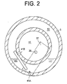
- the third opening 58B is located on the far side of the rotational axis of the drive shaft 7 as viewed from the hinge portion 23A of the lug plate 23, as shown in Fig. 4 .
- a bleed control valve 60 is disposed in the second radial hole 57.
- the bleed control valve 60 has a valve member 63, a weight member 65, a connecting rod 67 connecting the valve member 63 and the weight member 65, and a spring 69.
- the valve member 63 is located on the side of the rotational axis of the drive shaft 7 adjacent to the second opening 58A and disposed substantially in the first hole portion 57B for closing or partially obstructing the second opening 58A. When the valve member 63 comes into contact with the valve seat 57A, the valve member 63 closes the second opening 58A.
- the weight member 65 is located on the side of the rotational axis of the drive shaft 7 adjacent to the third opening 58B and disposed in the second hole portion 57C for partially obstructing the first opening 61A.
- the spring 69 is interposed between the valve member 63 and the projection 57D for urging the valve member 63 in the direction that opens the second opening 58A.
- a tubular spacer 71 is provided in the opening 1C with the front end thereof fitted on the rear end of the drive shaft 7 and the rear end thereof in slidably contact with the valve unit 9 for urging the drive shaft 7 forward.
- the valve unit 9 has therethrough a restriction hole 9A that interconnects the internal space of the spacer 71 and the suction chamber 11.
- the oil guide groove 3B, the oil guide hole 3C, the shaft hole 3A, the first radial hole 55, a part of the second radial hole 57, the first axial hole 59, the second axial hole 61, the internal space of the spacer 71 and the restriction hole 9A cooperate to form a bleed passage of the present invention.
- the oil guide groove 3B, the oil guide hole 3C, the shaft hole 3A, the first radial hole 55, the first axial hole 59, the second axial hole 61, the internal space of the spacer 71 and the restriction hole 9A cooperate to form a first passage of the present invention.
- a part of the second radial hole 57, the second axial hole 61, the internal space of the spacer 71 and the restriction hole 9A cooperate to form a second passage of the present invention.
- the conduit 51 is connected to the suction chamber 11 through a condenser 73, an expansion valve 75 and an evaporator 77.
- the compressor, the condenser 73, the expansion valve 75, the evaporator 77 and the conduit 51 cooperate to form a refrigeration system.
- Refrigerant gas mixed with lubricating oil is sealed in the refrigeration system.
- control valve 37 is operable to adjust the pressure in the crank chamber 15 in accordance with the pressure in the suction chamber 11 and the flow rate of the refrigerant gas thereby to change the inclination angle of the swash plate 29, thus varying the displacement of the compressor.
- crank chamber 15 there exist a region in the crank chamber 15 that is rich in lubricating oil and a region poor in lubricating oil.
- the region in the crank chamber 15 adjacent to the inner periphery of the front housing 3 is rich in lubricating oil and the region in the crank chamber 15 adjacent to the drive shaft 7 is poor because the centrifugal force due to the rotation of the swash plate 29, the drive shaft 7 and so forth forces the lubricating oil in the crank chamber 15 toward the inner periphery of the front housing 3.
- the region in the crank chamber 15 adjacent to the bottom of the compressor is rich in lubricating oil and the region adjacent to the top of the compressor is poor.
- the inner periphery of each cylinder bore 1A is rich in lubricating oil.
- the bleed passage of this publication has only a single passage formed by a single radial hole and a single axial hole in the drive shaft.
- the radial hole is merely in communication at the outer periphery of the drive shaft with the crank chamber. In this structure, an adequate amount of lubricating oil cannot be moved from the crank chamber to the suction chamber through the bleed passage.
- the bleed control valve 60 When the drive shaft 7 is rotated at a high speed, for example, while the vehicle is running at a high speed, the bleed control valve 60 is operated under an increased centrifugal force, so that the weight member 65 is moved away from the axis of the drive shaft 7 against the urging force of the spring 69 thereby to cause the valve member 63 to move in the direction that closes the second opening 58A.
- the valve member 63 When the drive shaft 7 is rotated at a still higher speed, the valve member 63 is in contact with the valve seat 57A, as shown in Fig. 6 .
- the proportion of the flow rate of refrigerant gas passing through the first passage to refrigerant gas passing through the bleed passage increases, while the proportion of the flow rate of refrigerant gas passing through the second passage to refrigerant gas passing through the bleed passage decreases. That is, the increase in the proportion of the flow rate of refrigerant gas passing through the first passage and the decrease in the proportion of the flow rate of refrigerant gas passing through the second passage are achieved by use of a single bleed control valve 60.
- the region in the crank chamber 15 adjacent to the inner periphery of the front housing 3 is rich in lubricating oil, from which the refrigerant gas containing a large amount of lubricating oil is easily flowed into the first radial hole 55 through the oil guide groove 3B and the oil guide hole 3C.
- the lubricating oil thus flowing toward the first radial hole 55 passes through the shaft seal 17, to which a large amount of lubricating oil is supplied, so that the durability of the rubber of the shaft seal 17 is enhanced.
- the increase in the proportion of the flow rate of refrigerant gas passing through the first passage causes the refrigerant gas containing a large amount of lubricating oil in the crank chamber 15 to be delivered in large quantities to the suction chamber 11 through the first passage.
- the amount of lubricating oil in the crank chamber 15 is thus adjusted appropriately and, therefore, excessive stirring of the lubricating oil by the swash plate 29 does not occur. Heating of the lubricating oil due to shear stress is reduced and decreasing of the viscosity of the lubricating oil is reduced, accordingly.
- the sliding surfaces between the swash plate 29 and the shoes 35 are appropriately lubricated.
- refrigerant gas drawn from the suction chamber 11 to the cylinder bore 1A contains a large amount of lubricating oil, so that the sliding surfaces between the inner wall surfaces of the cylinder bores 1A and the pistons 21 are also lubricated adequately.
- the compressor offers excellent durability during the high-speed operation of the compressor.
- the refrigeration system does not have any problem of refrigerating capacity because the pistons 21 then reciprocate at a high speed.
- the bleed control valve 60 When the drive shaft 7 is rotated at a low speed, for example, while the vehicle is running at a low speed, the bleed control valve 60 is operated under a decreased centrifugal force, so that the weight member 65 is moved toward the axis of the drive shaft 7 due to the urging force of the spring 69 thereby to cause the valve member 63 to move in the direction that opens the second opening 58A.
- the weight member 65 When the drive shaft 7 is rotated at a still lower speed, the weight member 65 is in contact with the projection 57D thereby to close half the first opening 61A, as shown in Fig. 5 .
- the proportion of the flow rate of refrigerant gas passing through the first passage to refrigerant gas passing through the bleed passage decreases, while the proportion of the flow rate of refrigerant gas passing through the second passage to refrigerant gas passing through the bleed passage increases. That is, the decrease in the proportion of the flow rate of refrigerant gas passing through the first passage and the increase in the proportion of the flow rate of refrigerant gas passing through the second passage are achieved by use of a single bleed control valve 60.
- the region in the crank chamber 15 adjacent to the drive shaft 7 is poor in lubricating oil, from which refrigerant gas having less amount of lubricating oil is flowed to the second radial hole 57.
- the increase in the proportion of the flow rate of refrigerant gas passing through the second passage causes the refrigerant gas containing a small amount of lubricating oil in the crank chamber 15 to be delivered in small quantities to the suction chamber 11 through the second passage. Therefore, the amount of lubricating oil contained in the refrigerant gas discharged out of the compressor to the external refrigeration system is decreased during the low-speed operation of the compressor, so that the refrigeration system offers high refrigerating capacity.
- the lubricating oil in the crank chamber 15 is increased during the low-speed operation of the compressor, the lubricating oil is merely stirred by the swash plate 29 rotating at a low speed. Heating of the lubricating oil due to shear stress hardly occurs and the viscosity of lubricating oil is hardly decreased, accordingly. Therefore, the sliding surfaces between the swash plate 29 and the shoes 35 and also between the inner wall surfaces of the cylinder bores 1A and the pistons 21 can be lubricated properly.
- the control valve 37 adjusts the pressure in the crank chamber 15 for varying the displacement of the compressor.
- the first hole portion 57B and the second hole portion 57C have substantially the same diameter, and the valve member 63 is disposed substantially in the first hole portion 57B and the weight member 65 is disposed in the second hole portion 57C. Therefore, force acting on the valve member 63 and force acting on the weight member 65 are substantially the same, so that the valve member 63 is operated stably.
- This arrangement of the valve member 63 works effectively particularly for the variable displacement type swash plate compressor.
- the bleed control valve 60 may be arranged substantially within the drive shaft 7 without extending into the crank chamber 15. Further, the weight member 65 serves to partially obstruct the first opening 61A, thus requiring no valve for the adjustment, with the result that the compressor can be made simple in structure.
- the third opening 58B is located on the far side of the rotational axis of the drive shaft 7 as viewed from the hinge portion 23A of the lug plate 23.
- the check valve 45 is located downstream of the discharge chamber 13 with respect to the flowing of refrigerant gas in the compressor. Therefore, refrigerant gas containing lubricating oil is not delivered out of the compressor to the external refrigeration system when the compressor is operating at its minimum displacement. In addition, refrigerant gas containing lubricating oil in the external refrigeration system does not flow backward into the discharge chamber 13. More specifically, the refrigerant gas circulates through the crank chamber 15, the bleed passage, the suction chamber 11, the compression chamber, the discharge chamber 13 and the supply passage 41 during the operation of the compressor under its minimum displacement. Thus, lubricating oil also circulates through the crank chamber 15, the bleed passage, the suction chamber 11, the compression chamber, the discharge chamber 13 and the supply passage 41.
- the lubricating oil in the discharge chamber 13 is delivered to the displacement control valve 37 through the oil supply passage 41A that is opened to the discharge chamber 13 at the lower part thereof.
- refrigerant gas containing less lubricating oil is delivered to the displacement control valve 37 through the refrigerant supply passage 41 B that is opened at a position above the oil supply passage 41A to the discharge chamber 13.
- the lubricating oil and the refrigerant gas that have been flowed to the displacement control valve 37 are then delivered to the crank chamber 15 through the secondary passage 41C.
- a part of the lubricating oil remains in the discharge chamber 13 and a necessary amount of lubricating oil moves into the crank chamber 15 to keep an appropriate amount of lubricating oil in the crank chamber 15.
- the refrigerant supply passage 41 B of the present embodiment has a larger cross-section than the oil supply passage 41A, a certain amount of lubricating oil is reserved in the discharge chamber 13.
- an appropriate amount of lubricating oil is kept in the crank chamber 15.
- the above-described compressor offers excellent sliding characteristics during high-speed rotation of the drive shaft 7.
- the compressor offers high refrigerating capacity during low-speed rotation of the drive shaft 7.
- the clutchless swash plate compressor of the second embodiment differs from that of the first embodiment in that the drive shaft 7 has therein a third axial hole 70 and the first radial hole 55, dispensing with the first axial hole 59, the second axial hole 61 and the second radial hole 57 of the first embodiment.
- the third axial hole 70 is coaxial with the drive shaft 7, and communicates with the first radial hole 55 and the opening 1C.
- the oil guide groove 3B, the oil guide hole 3C, the shaft hole 3A, the first radial hole 55, the third axial hole 70, the internal space of the spacer 71 and the restriction hole 9A cooperate to form the bleed passage of the present invention, and serves as the first passage of the present invention.
- the rest of the structure of the compressor of the second embodiment is substantially the same as that of the compressor of the first embodiment.
- the bleed passage is formed only by the first passage that communicates with the region in the crank chamber 15 rich in lubricating oil. Because the compressor of the second embodiment has neither the second passage that communicates with the region in the crank chamber 15 poor in lubricating oil nor the bleed control valve for varying the openings of the first passage and the second passage, the structure of the compressor is simplified. The other operations and effects of the second embodiment are substantially the same as those of the first embodiment.
- the bleed passage may directly interconnect the crank chamber 15 and the suction chamber 11.
- the bleed passage indirectly interconnects the crank chamber 15 and the suction chamber 11 via a suction passage that communicates with the suction chamber 11.
- the bleed passage may have the first passage and the second passage, though the bleed passage may have any other passage.
- the first passage communicates with any region rich in lubricating oil and the second passage communicates with any region poor in lubricating oil. Whether a region is rich or poor in lubricating oil is determined by relative comparison.
- any valve movable depending on the rotational speed of the drive shaft of the compressor may be used as the bleed control valve 60.
- a solenoid-operated valve whose valve member is movable in response to electrical signals transmitted from a speed sensor detecting the rotational speed of the drive shaft or from an acceleration sensor detecting the centrifugal force may be used as the bleed control valve 60.
- a mechanical valve may be employed which has a weight member movable under the centrifugal force to operate its valve member.
- a plurality of bleed control valves may be used as long as the proportions of the flow rates of refrigerant gas passing through the first passage and the second passage to the flow rate of refrigerant gas passing through the bleed passage are variable.
- a bypass conduit 79 for connection between the discharge chamber 13 and the conduit 51 so as to bypass the check valve 45 and a bypass valve 81 disposed in the bypass conduit 79.
- the bypass valve 81 is opened. Therefore, the lubricating oil flowed from the crank chamber 15 into the discharge chamber 13 through the suction chamber 11 and the compression chamber is delivered out of the compressor to the external refrigeration system without flowing through the check valve 45. Thus, the temperature rise in the crank chamber 15 during high-speed operation of the compressor is further prevented. In a compressor in which a sufficient space is not secured for the discharge chamber 13 due to the structure of the compressor, the amount of lubricating oil returned from the discharge chamber 13 to the crank chamber 15 can be reduced and the temperature rise in the crank chamber 15 can be prevented, accordingly.
- the bypass valve 81 may be of any type such as a bimetal type, a wax type, an electromagnetic type and the like.
- the control valve 37 has a solenoid that is excited by an external signal and decreases the opening of the supply passage 41 thereby to increase the displacement of the compressor.
- the solenoid may be excited to increase the displacement of the compressor thereby to open the check valve 45 when the temperature detected by a temperature sensor exceeds a critical value.
- the temperature sensor may be provided within the compressor, for example, in the crank chamber 15 or outside the compressor.
- the lubricating oil flowed from the crank chamber 15 to the suction chamber 11 during high-speed operation of the compressor is delivered to the external refrigeration system through the compression chamber, the discharge chamber 13 and the check valve 45. Meanwhile, refrigerant gas is returned from the external refrigerant system to the compressor, so that the temperature rise in the crank chamber 15 during high-speed operation of the compressor with the air conditioner of the vehicle turned off is further prevented.
- the amount of lubricating oil returned from the discharge chamber 13 to the crank chamber 15 through the refrigerant supply passage 41B is reduced, which helps to prevent the temperature rise in the crank chamber 15.
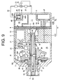
- a circlip 83 fixedly mounted on the drive shaft 7 and a shim 85 provided between the swash plate 29 and the circlip 83 for restricting the minimum inclination angle of the swash plate 29, as shown in Fig. 9 .
- the circlip 83 has a flat and annular shape.
- the shim 85 is made of a shape memory alloy so that the shim 85 having normally a flat and annular shape during normal operation of the compressor has its axial length increased, for example, by being deformed into a funnel shape, when the temperature in the crank chamber 15 rises to a preset temperature.
- the shim 85 changes its shape so as to urge the swash plate 29 whose inclination angle is then minimum, thereby increasing the inclination angle of the swash plate 29. Consequently, the displacement of the compressor is increased to open the check valve 45. Therefore, the lubricating oil flowed from the crank chamber 15 to the suction chamber 11 during high-speed operation of the compressor is delivered to the external refrigeration system through the compression chamber, the discharge chamber 13 and the check valve 45.
- the shim 85 may be of a bimetal type.
- the plain bearings 27, 19 may be substituted with radial roller bearings, so that the spaces between the rollers of the bearings serve as part of the bleed passage.
- the proportions of the flow rates of refrigerant gas passing through the first passage and the second passage to the flow rate of refrigerant gas passing through the bleed passage may be changed as required.
- the linkage 31 is not limited to the form as described in the above-described embodiments, but may be modified in various manners.
- a thrust bearing or a spring may be employed.
- a clutch less swash plate compressor compressing refrigerant gas mixed with lubricating oil is used for an air conditioner of a vehicle.
- the clutchless swash plate compressor includes a bleed passage, a supply passage and a displacement control valve.
- the supply passage includes an oil supply passage and a refrigerant supply passage both by which the discharge chamber communicates with the displacement control valve.
Landscapes
- Engineering & Computer Science (AREA)
- Mechanical Engineering (AREA)
- General Engineering & Computer Science (AREA)
- Compressors, Vaccum Pumps And Other Relevant Systems (AREA)
- Compressor (AREA)
Applications Claiming Priority (1)
| Application Number | Priority Date | Filing Date | Title |
|---|---|---|---|
| JP2008040551A JP2009197685A (ja) | 2008-02-21 | 2008-02-21 | 斜板式圧縮機 |
Publications (1)
| Publication Number | Publication Date |
|---|---|
| EP2093423A1 true EP2093423A1 (fr) | 2009-08-26 |
Family
ID=40673231
Family Applications (1)
| Application Number | Title | Priority Date | Filing Date |
|---|---|---|---|
| EP09153217A Withdrawn EP2093423A1 (fr) | 2008-02-21 | 2009-02-19 | Compresseur de type à disque oblique dépourvu d'embrayage |
Country Status (2)
| Country | Link |
|---|---|
| EP (1) | EP2093423A1 (fr) |
| JP (1) | JP2009197685A (fr) |
Cited By (3)
| Publication number | Priority date | Publication date | Assignee | Title |
|---|---|---|---|---|
| EP2878821A1 (fr) * | 2013-11-06 | 2015-06-03 | Kabushiki Kaisha Toyota Jidoshokki | Compresseur de type plateau oscillant à déplacement variable |
| US9163620B2 (en) | 2011-02-04 | 2015-10-20 | Halla Visteon Climate Control Corporation | Oil management system for a compressor |
| EP4209677A4 (fr) * | 2020-09-02 | 2024-05-15 | Valeo Japan Co., Ltd. | Compresseur du type à plateau oscillant et à capacité variable |
Families Citing this family (1)
| Publication number | Priority date | Publication date | Assignee | Title |
|---|---|---|---|---|
| JP5413834B2 (ja) * | 2009-11-27 | 2014-02-12 | サンデン株式会社 | 往復動圧縮機 |
Citations (7)
| Publication number | Priority date | Publication date | Assignee | Title |
|---|---|---|---|---|
| US4685866A (en) * | 1985-03-20 | 1987-08-11 | Kabushiki Kaisha Toyoda Jidoshokki Seisakusho | Variable displacement wobble plate type compressor with wobble angle control unit |
| JPH10205446A (ja) | 1996-03-12 | 1998-08-04 | Toyota Autom Loom Works Ltd | クラッチレス圧縮機 |
| JP2000265960A (ja) | 1999-03-15 | 2000-09-26 | Toyota Autom Loom Works Ltd | 流体機械 |
| EP1477671A2 (fr) * | 2003-05-16 | 2004-11-17 | Kabushiki Kaisha Toyota Jidoshokki | Appareil de commande pour compresseur à déplacement variable |
| EP1614896A1 (fr) * | 2004-07-09 | 2006-01-11 | Kabushiki Kaisha Toyota Jidoshokki | Compresseur à capacité variable |
| EP1788246A1 (fr) * | 2005-11-16 | 2007-05-23 | Kabushiki Kaisha Toyota Jidoshokki | Compresseur à déplacement variable comprenant un appareil de réglage pour un système de refrigération de véhicule, et une valve de réglage |
| WO2007111194A1 (fr) * | 2006-03-29 | 2007-10-04 | Kabushiki Kaisha Toyota Jidoshokki | Compresseur |
-
2008
- 2008-02-21 JP JP2008040551A patent/JP2009197685A/ja active Pending
-
2009
- 2009-02-19 EP EP09153217A patent/EP2093423A1/fr not_active Withdrawn
Patent Citations (7)
| Publication number | Priority date | Publication date | Assignee | Title |
|---|---|---|---|---|
| US4685866A (en) * | 1985-03-20 | 1987-08-11 | Kabushiki Kaisha Toyoda Jidoshokki Seisakusho | Variable displacement wobble plate type compressor with wobble angle control unit |
| JPH10205446A (ja) | 1996-03-12 | 1998-08-04 | Toyota Autom Loom Works Ltd | クラッチレス圧縮機 |
| JP2000265960A (ja) | 1999-03-15 | 2000-09-26 | Toyota Autom Loom Works Ltd | 流体機械 |
| EP1477671A2 (fr) * | 2003-05-16 | 2004-11-17 | Kabushiki Kaisha Toyota Jidoshokki | Appareil de commande pour compresseur à déplacement variable |
| EP1614896A1 (fr) * | 2004-07-09 | 2006-01-11 | Kabushiki Kaisha Toyota Jidoshokki | Compresseur à capacité variable |
| EP1788246A1 (fr) * | 2005-11-16 | 2007-05-23 | Kabushiki Kaisha Toyota Jidoshokki | Compresseur à déplacement variable comprenant un appareil de réglage pour un système de refrigération de véhicule, et une valve de réglage |
| WO2007111194A1 (fr) * | 2006-03-29 | 2007-10-04 | Kabushiki Kaisha Toyota Jidoshokki | Compresseur |
Cited By (5)
| Publication number | Priority date | Publication date | Assignee | Title |
|---|---|---|---|---|
| US9163620B2 (en) | 2011-02-04 | 2015-10-20 | Halla Visteon Climate Control Corporation | Oil management system for a compressor |
| EP2878821A1 (fr) * | 2013-11-06 | 2015-06-03 | Kabushiki Kaisha Toyota Jidoshokki | Compresseur de type plateau oscillant à déplacement variable |
| US9752563B2 (en) | 2013-11-06 | 2017-09-05 | Kabushiki Kaisha Toyota Jidoshokki | Swash plate type variable displacement compressor |
| EP4209677A4 (fr) * | 2020-09-02 | 2024-05-15 | Valeo Japan Co., Ltd. | Compresseur du type à plateau oscillant et à capacité variable |
| US12345246B2 (en) | 2020-09-02 | 2025-07-01 | Valeo Japan Co., Ltd. | Variable-displacement swash plate type compressor |
Also Published As
| Publication number | Publication date |
|---|---|
| JP2009197685A (ja) | 2009-09-03 |
Similar Documents
| Publication | Publication Date | Title |
|---|---|---|
| US8360742B2 (en) | Swash plate compressor | |
| EP2182213B1 (fr) | Compresseur de type à déplacement variable doté d'un mécanisme de contrôle du déplacement | |
| EP1918583B1 (fr) | Soupape d'admission pour un compresseur | |
| US6149398A (en) | Variable capacity piston- operated refrigerant compressor with an oil separating means | |
| US7972119B2 (en) | Variable displacement compressor | |
| EP0940581A2 (fr) | Amortisseur des pulsations de pression pour le réfoulement d'un compresseur | |
| EP1798499A2 (fr) | Compresseur frigorifique avec séparateur d'huile | |
| US20090223244A1 (en) | Swash plate type compressor | |
| JPS62674A (ja) | 角度可変揺動斜板型可変容量圧縮機の容量制御装置 | |
| EP2096308B1 (fr) | Compresseur à déplacement variable de type brise-flot | |
| EP1959137B1 (fr) | Robinet d'étranglement d'aspiration de compresseur de type à déplacement variable | |
| US6672844B2 (en) | Apparatus and method for controlling variable displacement compressor | |
| JP5341827B2 (ja) | 可変容量圧縮機 | |
| CN101503993B (zh) | 旋转斜盘式压缩机 | |
| US6578372B2 (en) | Apparatus and method for controlling variable displacement compressor | |
| US20030021698A1 (en) | Control valve of variable displacement compressor | |
| JP4648845B2 (ja) | 斜板型および揺動斜板型の可変容量圧縮機 | |
| JP2009293386A (ja) | 圧縮機 | |
| JP2009197685A (ja) | 斜板式圧縮機 | |
| US20120247319A1 (en) | Swash plate type variable displacement compressor | |
| US9797638B2 (en) | Compressor | |
| JP2007009720A (ja) | 可変容量型圧縮機 | |
| JP7511702B2 (ja) | 斜板式コンプレッサー | |
| JP2017150315A (ja) | 可変容量型斜板式圧縮機 | |
| JP2010112242A (ja) | 圧縮機 |
Legal Events
| Date | Code | Title | Description |
|---|---|---|---|
| PUAI | Public reference made under article 153(3) epc to a published international application that has entered the european phase |
Free format text: ORIGINAL CODE: 0009012 |
|
| 17P | Request for examination filed |
Effective date: 20090219 |
|
| AK | Designated contracting states |
Kind code of ref document: A1 Designated state(s): AT BE BG CH CY CZ DE DK EE ES FI FR GB GR HR HU IE IS IT LI LT LU LV MC MK MT NL NO PL PT RO SE SI SK TR |
|
| AX | Request for extension of the european patent |
Extension state: AL BA RS |
|
| AKX | Designation fees paid |
Designated state(s): AT BE BG CH CY CZ DE DK EE ES FI FR GB GR HR HU IE IS IT LI LT LU LV MC MK MT NL NO PL PT RO SE SI SK TR |
|
| STAA | Information on the status of an ep patent application or granted ep patent |
Free format text: STATUS: THE APPLICATION HAS BEEN WITHDRAWN |
|
| 18W | Application withdrawn |
Effective date: 20100617 |