EP2093469A2 - Manchon de compression - Google Patents
Manchon de compression Download PDFInfo
- Publication number
- EP2093469A2 EP2093469A2 EP09150232A EP09150232A EP2093469A2 EP 2093469 A2 EP2093469 A2 EP 2093469A2 EP 09150232 A EP09150232 A EP 09150232A EP 09150232 A EP09150232 A EP 09150232A EP 2093469 A2 EP2093469 A2 EP 2093469A2
- Authority
- EP
- European Patent Office
- Prior art keywords
- transmission element
- section
- peripheral surface
- element according
- flange
- Prior art date
- Legal status (The legal status is an assumption and is not a legal conclusion. Google has not performed a legal analysis and makes no representation as to the accuracy of the status listed.)
- Granted
Links
Images




Classifications
-
- F—MECHANICAL ENGINEERING; LIGHTING; HEATING; WEAPONS; BLASTING
- F16—ENGINEERING ELEMENTS AND UNITS; GENERAL MEASURES FOR PRODUCING AND MAINTAINING EFFECTIVE FUNCTIONING OF MACHINES OR INSTALLATIONS; THERMAL INSULATION IN GENERAL
- F16L—PIPES; JOINTS OR FITTINGS FOR PIPES; SUPPORTS FOR PIPES, CABLES OR PROTECTIVE TUBING; MEANS FOR THERMAL INSULATION IN GENERAL
- F16L13/00—Non-disconnectable pipe joints, e.g. soldered, adhesive, or caulked joints
- F16L13/14—Non-disconnectable pipe joints, e.g. soldered, adhesive, or caulked joints made by plastically deforming the material of the pipe, e.g. by flanging, rolling
- F16L13/146—Non-disconnectable pipe joints, e.g. soldered, adhesive, or caulked joints made by plastically deforming the material of the pipe, e.g. by flanging, rolling by an axially moveable sleeve
-
- F—MECHANICAL ENGINEERING; LIGHTING; HEATING; WEAPONS; BLASTING
- F16—ENGINEERING ELEMENTS AND UNITS; GENERAL MEASURES FOR PRODUCING AND MAINTAINING EFFECTIVE FUNCTIONING OF MACHINES OR INSTALLATIONS; THERMAL INSULATION IN GENERAL
- F16L—PIPES; JOINTS OR FITTINGS FOR PIPES; SUPPORTS FOR PIPES, CABLES OR PROTECTIVE TUBING; MEANS FOR THERMAL INSULATION IN GENERAL
- F16L37/00—Couplings of the quick-acting type
- F16L37/08—Couplings of the quick-acting type in which the connection between abutting or axially overlapping ends is maintained by locking members
- F16L37/12—Couplings of the quick-acting type in which the connection between abutting or axially overlapping ends is maintained by locking members using hooks, pawls, or other movable or insertable locking members
- F16L37/138—Couplings of the quick-acting type in which the connection between abutting or axially overlapping ends is maintained by locking members using hooks, pawls, or other movable or insertable locking members using an axially movable sleeve
Definitions
- the invention relates to a transmission element for axially compressible workpiece connections.
- the invention further relates to an arrangement for producing a permanent connection.
- Transmission elements or arrangements of the type mentioned are known from the prior art.
- An undetachable connection, especially between a pipe and a fitting, is made using an axial pressing technique, for example, by a method as follows.
- a profiled, in particular provided with a certain number bead-like outer projections transmission element is placed on a pipe end.
- the encompassed by the transmission element tube end is pushed onto the possibly profiled support body of a shoulder-mounted fitting, so that the end faces of the tube and the transmission element abut the shoulder.
- an optionally profiled, for example, rioswülste having union compression sleeve is slid over the encompassed by the transmission element tube end in the direction of the shoulder of the fitting. Due to the interaction with the compression sleeve, the transmission element and the tube end are radially inwardly deformed on the support body, so that a positive, possibly also form-fitting connection is created.
- a disadvantage of this approach is, however, that only punctual forming forces are effected by the bead-like projections, whereby the Pressauer, in particular a required for the tightness of the permanent connection positive connection of the tube with the support body of the fitting can be affected.
- a separate sealing element such as an O-ring between the support body and the pipe end can be arranged.
- this increases the effort required to produce the permanent connection as well as the due diligence required to produce the permanent connection.
- the abutment described above of the end faces of the tube and of the transmission element at the shoulder of the fitting limits the selection of the materials from which the tube or the fitting can be manufactured.
- the pipe is a metal pipe or a composite pipe having a metal layer
- the fitting in this example is made of a metal or other kind of material which has a different chemical potential from the metal of the pipe the structure of the tube, in particular after the pressing process by contact corrosion, in the case of a composite tube for the eye of an observer, if necessary even invisible damage.
- the present invention is therefore based on the technical problem of specifying a transmission element and an arrangement with which or with which a permanent insoluble compound using an axial pressing technique can be produced by simple means.
- a transmission element for axially compressing workpieces having a flange portion and a transmission portion, wherein the transmission portion has a substantially cylindrical inner peripheral surface and wherein the wall thickness of the transmission portion tapers from the flange proximal end to the flange distal end.
- the inner circumferential surface of the transfer section is substantially cylindrical. This is to be understood that a pipe provided for a non-detachable connection should be insertable on the transfer section side into the transfer element, optionally by friction. Since many tubes have a circular outer cross section, therefore, a correspondingly adapted circular cylindrical configuration of the inner peripheral surface of the transfer section may be appropriate.
- the transmission element can also be designed to be suitable for other tube outer cross sections, for example elliptical or prismatic cross sections.
- the term cylindrical is therefore very broad.
- the substantially cylindrical inner peripheral surface may be modified by constructional features which only insignificantly change the cylindrical character of the surface, for example due to its small dimensions.
- an outer peripheral surface is advantageously created, which in the interaction with a suitable, pressed for the purpose of pressing sliding sleeve during the pressing process allows a more uniform application of force.
- imperfections in the press result between the support body of a fitting and a pipe, which impairs the tightness of a permanent connection, can be avoided. Measures in the form of additional sealing elements are also avoidable.
- the outer peripheral surface of the transmission section which is inclined relative to the center axis of the transmission element, makes possible at least partial force deflection from the axial direction into the radially inward direction.
- the transmission element according to the invention can be used in particular for axial pressing techniques.
- the flange portion advantageously provides a contact surface for the end face of a tube, which is to be inserted into the transmission element and pressed with this.
- material incompatibilities for example in the form of contact corrosion, can thus be avoided by a suitable selection of the materials of the flange section and of the pipe or composite pipe.
- the flange portion and the transmission portion may be integrally formed.
- the flange section and the transfer section are preferably connected via a bridge section, in particular by means of a recess.
- a substantial decoupling of the flange portion and the transfer section can be ensured, in particular during the pressing process.
- the wall thickness of the transmission element between the flange portion and the transmission section, ie at the bridge section is reduced, so that the forces transmitted to the transmission section by a sliding sleeve during the pressing process are transmitted to the flange section only in a substantially non-deforming thickness of the flange section. Therefore, the flange portion essentially retains its shape after the pressing operation, whereas the transmitting portion is deformed radially inward, and optionally with compression of the bridge portion also in the axial direction to the flange portion.
- the flange section and the transfer section can be connected by means of connecting elements, in particular plug connection elements.
- These connecting elements may be, for example, pins, projections and / or corresponding fitting grooves, which enable the, in particular frictional attachment of the flange portion to the transfer section or vice versa.
- the flange portion has a radially inwardly extending latching projection.
- the transmission element can be connected to a fitting at least non-positively.
- the structural design of one for the production of a permanent one Connection required fittings are simplified. This is because the fitting itself no longer has to have a shoulder which defines the pressing position of a pipe in the axial direction. Rather, it is sufficient if the fitting has a locking element corresponding to the latching projection arranged on the flange section of the transmission element, for example a latching groove.
- the inner circumferential surface of the flange portion in particular its shape or its diameter, can also be configured additionally or alternatively in a manner suitable for a press fit with the main body of a fitting. This makes it possible to achieve a frictional fit of the transmission element on a fitting, which may possibly be able to hold the transmission element and the fitting in a largely fixed position relative to one another even when forces are exerted during the pressing process.
- At least one axially extending web can be provided on the inner peripheral surface of the transfer section.
- the inner cross section of the transfer section can locally be narrowed along the extent of the web and thus an additional fixation of a pipe introduced into the transfer element on the transfer section side against rotational movements can be achieved. If at least two webs are provided, moreover, the pipe inserted into the transfer element can be more reliably centered relative to the central axis of the transfer element. In this way, manufacturing tolerances of the outer diameter of a take into account inserted pipe.
- the outer diameter of a tube differs from the standard outer diameter has a slight undersize, otherwise unwanted rotational movement of the tube could be triggered relative to the transmission element during handling of the tube inserted into the transmission element, which obstructs or impedes the pressing process.
- the inner peripheral surface of the transfer portion may be formed in the shape of a polygon. Also by this structural development of the transmission element according to the invention, an undesired rotational movement of an inserted tube can be inhibited.
- the outer peripheral surface of the transfer section is designed in the form of a cone segment.
- the production of the transfer section and optionally the production of workpieces, such as sliding sleeves, with adapted to these transfer sections interaction surfaces, which are provided together for the made by means of axial pressing technology production of a permanent connection simplified.
- a high degree of compatibility between the sliding sleeves and the transmission elements can be achieved.
- the angle of inclination of the outer peripheral surface of the transfer section relative to the central axis may be between 5 ° and 15 °, in particular 10 °.
- the stability of the arrangement during the pressing process can be promoted by this configuration. Because a sliding sleeve with a correspondingly adapted inner contour can be so gentle but with steadily increasing application of force to the transmission section, which benefits the quality of the press result.
- At least one opening is provided on the flange section of the proximal end of the transfer section and / or on the bridge section.
- the opening allows a user to control the recommended, optionally prescribed engagement of the pipe end in the transmission element.
- the control can be carried out both before and after the pressing process.
- the opening has a longitudinal extension in the circumferential direction, it can furthermore promote the decoupling of the flange section and of the transfer section. Because at the opening between the flange and transmission section no transmitted to the transmission section forces are forwarded to the flange. The stress on the flange portion during the pressing process can be additionally reduced.
- the outer peripheral surface of the flange portion may have a chamfer on the end face.
- an interaction surface for pressing tools can be created, which are actuated by means of a radially inward movement. If, for example, a section of a pressing jaw, which has a corresponding angle of inclination relative to the center axis of the transmission element, abuts against the chamfer, the dynamics caused by the radially inward movement can be at least partially deflected into a pressing force acting in the axial direction.
- tools can be used for the compression in the axial direction, which were actually designed for the compression in the radially inward direction. In this way, such tools inherent advantages such as small physical dimensions and / or light weight can be exploited.
- the outer peripheral surface of the transfer section and / or the chamfer of the flange section is preferably designed to promote sliding. In this way, the pressing process can be facilitated.
- the outer peripheral surface and / or the chamfer form slidable can be done in different ways. It is possible to form the respective portions of the flange portion or transfer portion in two parts, and to manufacture the surfaces of a material such as polytetrafluoroethylene or the like. However, it is also possible to increase the slipperiness by means of a sliding-promoting coating of the surfaces, for example with a bonded coating.
- the latching projection undercutting in particular annular recess.
- the undercut in particular promotes the flexibility of the latching projection, so that the latching projection can more easily overcome the walls of a corresponding latching groove on the base body of a fitting and can latch in the manner of a snap lock.
- the undercut material of the transmission element is removed, whereby the weight of the transmission element is reduced.
- the latching projection is chamfered on the side facing the front side of the flange portion. In this way, the production of an engagement of the latching projection can be facilitated in a arranged on a fitting latching groove, in particular by means of a movement in the axial direction.
- the inner peripheral surface of the locking projection may be formed in the shape of a polygon. In this way, unwanted rotational movements of the flange portion and the transmission element relative to the fitting, when the locking projection and the locking groove are engaged, avoid. Additionally or alternatively, of course, anti-rotation webs, possibly also Drehêtswülste be provided on the inner peripheral surface of the locking projection. This can also reduce the susceptibility to rotary motion.
- the transmission element is made of a up to a temperature of 95 ° C, in particular 85 ° C dimensionally stable, heat-resistant plastic.
- plastics come from the group of polysulfones or polyphenylsulfones, from the group of thermally stabilized, in particular fiber-reinforced polyamides or polyvinylidene fluoride into consideration.
- the transmission elements meet the requirements placed on permanent connections in the drinking water or heating installation area.
- the abovementioned materials have advantageous forming properties and a low tendency to contact corrosion. Transmission elements of these Materials are therefore particularly suitable for use with pipes of a metal material or for use with composite metal pipes comprising a layer of metal material.
- the technical problem is also solved by an arrangement for producing a permanent connection with a fitting, wherein the fitting has a profiled supporting body and a main body, with a transmission element, wherein the transmission element has a flange portion and a in the Substantially cylindrical inner peripheral surface having the transfer portion, wherein the wall thickness of the transfer section from the flange proximal end to the flange distal end tapers, and with a sliding sleeve, wherein the contour of the inner peripheral surface of the sliding sleeve is adapted to the contour of the outer peripheral surface of the transfer section the transmission element surrounds the support body and at least partially surrounds the base body, wherein the sliding sleeve is partially pushed onto the transmission section, and wherein the inner circumferential surface d he sliding sleeve and the outer peripheral surface of the transfer section are at least partially frictionally engaged, solved.
- the transmission element and the fitting may, for example, be in a frictional engagement by means of a press fit.
- the fitting makes it possible to interlock the transmission element with the fitting in the axial direction by engaging the latching projection arranged on the flange section of the transmission element into the latching groove arranged on the fitting base body. In this way, the fitting and the transmission element can be kept in a defined position before the pressing process. In addition, it is no longer necessary to provide the fitting with a serving as a facility for the faces of the other to be pressed workpieces shoulder. In particular, the requirements for the production of fittings are thus simplified.
- the fitting can also have connection sections of another, basically any type.
- the fitting may also comprise a valve, a ball valve or a similar fitting or several similar fittings.
- the fitting has only two pipe connections comprising a support body.
- the support body preferably has on its outer circumferential surface a profile which, in the course of the pressing process, transforms and optionally displaces the material of a pipe to be compressed into a volume into which it can flow.
- the profile of the support body may, for example, comprise a plurality of ring-shaped circumferential grooves bounded by annular circumferential dividers.
- the contour of the inner peripheral surface of the sliding sleeve is preferably adapted to the contour of the outer peripheral surface of the transfer section.
- the transmission section for example, cone-shaped, the inner peripheral surface of the sliding sleeve on a correspondingly adapted cone segment shape.
- the inventive arrangement can be created by the inventive arrangement, a system of workpieces, which is available for a user in the trade.
- the user merely has to make sure that the shape of the outer cross section and / or the outer diameter of the pipes to be pressed by him to the respective dimensions of the fitting, for example, the support body or the transmission element, for example, the transmission section are suitable.
- the wall of the sliding sleeve is formed in cross-section substantially wedge-shaped.
- the sliding of the sliding sleeve is simplified to the transmission portion of the transmission element.
- the sliding sleeve may have at its wide end a, in particular slide-promoting bevel formed.
- a, in particular slide-promoting bevel formed.
- an interaction surface for pressing tools can be created, which are actuated by means of a radially inward movement.
- tools can be used for the compression in the axial direction, which were actually designed for the compression in the radially inward direction.
- such tools inherent advantages such as low spatial Dimensions and / or low weight can be exploited. Due to the slide-enhancing design of the chamfer, the pressing process can be facilitated.
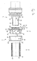
- Fig. 1a shows in a cross-sectional view four workpieces: a fitting 4, a transmission element 2, a sliding sleeve 6 and a pipe. 8
- the fitting 4 has a profile body having a support body 10.
- the profile consists in this particular example of four annular circumferential grooves 12, which are delimited from each other by three interposed, annular peripheral dividers 14.
- the inner peripheral surface 16 of the support body 10 is formed substantially cylindrical, but the support body walls are slightly beveled radially outwardly at the distal end of the support body 10 in order to make the cross-sectional transition continuous.
- the support body 10 extends in this example of a base body 18, which has on the outer peripheral surface an annular circumferential locking groove 20.
- the fitting 4 in Fig. 1a upstream is a transmission element 2 according to the present invention.
- the transmission element 2 has a flange section 22 facing the fitting 4, a transmission section 24 and a bridge section 28 formed between the flange section 22 and the transmission section 24 by means of a recess 26.
- a radially inwardly extending latching projection 30 which is slightly bevelled on the end face 32 of the flange portion 22 side facing.
- the latching projection 30 is in particular designed such that it engages in the locking groove 20 arranged on the fitting 4, which is shown here by way of example, and has an axial Lock can cause.
- the transmission element 2 is on the outer peripheral surface 34 of the flange portion 22 on the front side beyond a chamfer 36 is arranged, which can serve as an interaction surface with a pressing tool (not shown). Further, the flange portion 22 at its radially inwardly extending region on an opening to the transfer section 24 investment recess 38, on which the end face 40 of a tube 8 can come into abutment.
- the inner peripheral surface of the flange portion 22 is formed in this example as a polygon. In this way, in the interaction with the inner peripheral surface of the flange portion 22 opposite outer peripheral surface of the fitting body 18, an additional safeguard against undesired rotational movement of the transmission element 2 relative to the fitting 4 can be achieved.
- the transfer section 24 of the transfer element 2 has an end that is proximal to the flange section 22 to the wall thickness tapering to the flange section 22.
- the outer peripheral surface 42 of the transfer section 24 is formed as a cone segment surface which is inclined at an angle of about 10 ° to the central axis 44 of the transfer element 2.
- the wall of the transfer section 24 thus has a substantially wedge shape.
- a bridge portion 28 is formed so that the flange portion 22 and the transmission portion 24 are integrally connected to each other.
- the flange portion 22 and the transfer portion 24 may be workpieces which can be separated from one another and which can be connected to one another by means of suitable connecting elements (not shown), for example plug connection elements such as pins, springs and / or fitting grooves.
- the bridge section 28 in this example has four openings 46 which have a substantially circumferentially extending extension and, in addition, a recess 48 extending into the transfer section 24.
- the apertures 46 allow a user to visually inspect the position of the workpieces before and optionally after the pressing operation.
- the openings 46 can also have a different shape or be arranged at a different location, for example exclusively at the transfer section 24.
- the number of openings 46 can basically be chosen freely.
- four webs 50 extending in the axial direction are provided on the inner peripheral surface of the bridge section 28 and of the transfer section 24, which locally slightly narrow the internal cross section of the transfer element 2 on the transfer section 24, and in this example also on the bridge section 28, and thus provide protection against undesired rotational movements ensure a introduced into the transmission element 2 tube 8 relative to the transmission element 2.
- the webs 50 extend according to Fig. 1a from Of course, it is also possible to provide the webs 50 only at the transfer section 24 in order to obtain the desired anti-rotation effect.
- the number of webs 50 can basically be chosen freely.
- a design of the inner peripheral surface of the transfer section 24 and / or the bridge section 28 as a polygon may be provided.
- the transmission element 2 may be made of a polysulfone, polyphenylsulfone or thermally stabilized, in particular fiber-reinforced polyamide.
- a polysulfone polysulfone
- polyphenylsulfone or thermally stabilized, in particular fiber-reinforced polyamide.
- other materials are conceivable, such as polyvinylidene fluoride.
- a sliding sleeve 6 having an inner circumferential surface 52 which is formed as an interaction surface with the outer peripheral surface 42 of the transfer section 24 and therefore in this particular example has the shape of a hollow cone segment.
- the angle of inclination of the conical segment surface relative to the central axis 44 is accordingly adapted to the angle of inclination of the outer peripheral surface 42 of the transfer section 24.
- the wall 54 of the sliding sleeve 6 has a substantially wedge shape. This wedge shape is only modified by a flange-like projection 56 at the wide end of the wedge, in other words on the side facing away from the transmission element 2 side of the sliding sleeve 6.
- the sliding sleeve 6 at its wide end, in other words at the end where the wall 54, the largest Thickness, a chamfer 58 on which, for example, a pressing tool (not shown) can attack.
- the arrangement shown is a composite tube 8, which comprises three layers 60, 62, 64.
- the inner layer 60 may consist of a cross-linked polyethylene (PEX), the middle layer 62 of a metal such as aluminum, and the outer layer 64 of a particular mechanical stress-resisting or aesthetics-sufficient plastic.
- the composite pipe 8 is to be understood only as an example.
- the in Fig. 1a Arrangement shown also comprise a single-layer pipe, for example made of a plastic or a metal or metal material.
- the cross section of the tube 8 is not limited in principle.
- the relevant diameters of the workpieces ie the outer diameter of the support body 10 of the fitting 4 and the inner diameter of the tube 8 and the outer diameter of the tube 8 and the inner diameter of the transfer section 24 of the transmission element 2 are suitable for each other or adapted to each other.
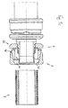
- Fig. 1b shown arrangement differs from the in Fig. 1a represented in that the transmission element 2 is fitted onto the fitting 4 or that the fitting 4 engages in the transmission element 2.
- the latching projection 30 arranged on the flange section 22 engages with the latching groove 20 arranged on the fitting base body 18 and thereby prevents axial movement. Axial movements could additionally or alternatively also be avoided by a press fit of the two workpieces become.
- the fitting base body 18 is encompassed substantially by the flange section 22 and the support body 10 substantially by the bridge section 28 and the transmission section 24, wherein the distal end of the support body 10 protrudes from the transmission element 2 on the transmission section side.
- this embodiment is not mandatory.
- distal end of the support body 10 and the distal end of the transfer section 24 come to lie approximately in the same perpendicular plane to the central axis 44 or that the distal end of the transfer section 24 even projects beyond the support body 10. It can therefore be chosen an embodiment as appropriate for the intended application.
- Fig. 1c shown arrangement differs from the in Fig. 1b represented by the fact that the sliding sleeve 6 is plugged transmission side on the transmission element 2, wherein the inner peripheral surface 52 of the sliding sleeve 6 and the outer peripheral surface 42 of the transfer section 24, which are adapted to each other, at least partially in a frictional engagement.
- the sliding sleeve 6 is formed in this particular embodiment in relation to the transfer section 24 so that the inner peripheral surface 52 of the sliding sleeve 6 and the outer peripheral surface 42 of the transfer section 24 are not yet fully in contact for effecting frictional engagement.
- the distance is determined over which the sliding sleeve 6 is to be pressed against the flange portion 22 to the pressing process substantially complete and establish the unsolvable connection.
- other structural embodiments of the sliding sleeve 6 are also conceivable.
- the shape or contour of the outer circumferential surface of the sliding sleeve 6 is hardly subject to any restrictions.
- Fig. 1c Thus shows an inventive arrangement for producing a permanent connection, as it can acquire a user in the trade, and which is only to be supplemented by a pipe to be compressed 8 in order to make the pressing process can.
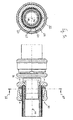
- Fig. 1d shows those from the Fig. 1a-c known arrangement in which the tube 8 is inserted into the cavity between the support body 10 of the fitting 4 and the transmission portion 24 of the transmission element 2.
- the tube interior can rest on the outer circumferential surface of the separating webs 14, in particular by frictional engagement.
- the end face 40 of the tube 8 is pushed up to the stop on the arranged on the flange portion 22 of the transmission element 2 investment recess 38.
- the outer peripheral surface 66 of the tube 8 is in this particular embodiment in frictional engagement with the inner peripheral surface of the four arranged on the inner peripheral surface of the transfer section 24, axially extending webs 50 (not visible), so that the tube 8 is rotationally inhibited and substantially centered with respect to the central axis 44 ,
- the openings 46 (not visible) which are partially bulged at the bridge section 28 and at the transfer section 24 allow the user to use the in Fig. 1d shown arrangement the proper position of the workpieces 2, 4, 6, 8 control each other.
- Fig. 1e shows the off Fig. 1d known arrangement, wherein a cross-sectional view along a plane perpendicular to the central axis 44 perpendicular plane (view along the arrows 68), the arrangement of the fitting 4, in particular the support body 10, the transmission element 2, in particular the flange portion 22 and the transmission portion 24, the sliding sleeve 6 and the tube 8, in particular the inner layer 60, middle layer 62 and outer layer 64, further illustrated.
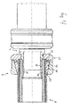
- the transfer section 24 transmits the pressing forces to the tube 8, which is radially inwardly deformed so that the separated by the dividers 14 grooves 12 on the support body 10 of the fitting 4 receive the displaced material of the tube 8, and thus a positive and positive connection can arise ,
- the end position after the pressing process is an end face of the sliding sleeve 6 on the flange 22 in abutment.
- the bridge section 28 has been converted in this example only in the radial direction, its axial extent is substantially equal to the expansion before the pressing operation.
- the bridge section 28 is covered by the thin-walled end of the sliding sleeve 6. However, it is also possible to operate the pressing process so far that the bridge section 28 is completely compressed in the axial direction, if appropriate.
- Fig. 2a-c show that in the Fig. 1a-f illustrated, special embodiment of the transmission element 2 according to the invention in three isometric views.
- a catch projection 30 undercutting in particular annular recess (not shown). By the undercut in particular the flexibility of the locking projection 30 is promoted.
- Fig. 3 shows an arrangement which comprises a transmission element 2, a sliding sleeve 6 and a composite tube 8.
- Fig. 3 is intended to illustrate that it is also possible for the transmission element 2 and the standing in frictional engagement sliding sleeve 6 only postpone to the pipe 8 before the arrangement of these three workpieces 2, 6, 8 attached to a fitting 4 as described above and then the pressing process is carried out.
- the order of the various process steps is therefore not on in the Fig. 1a-f illustrated example limited.
Landscapes
- Engineering & Computer Science (AREA)
- General Engineering & Computer Science (AREA)
- Mechanical Engineering (AREA)
- Mutual Connection Of Rods And Tubes (AREA)
- Forging (AREA)
Applications Claiming Priority (1)
| Application Number | Priority Date | Filing Date | Title |
|---|---|---|---|
| DE102008010084.6A DE102008010084B4 (de) | 2008-02-19 | 2008-02-19 | Übertragungselement für axial zu verpressende Werkstückverbindungen sowie Anordnung zur Herstellung einer unlösbaren Verbindung |
Publications (3)
| Publication Number | Publication Date |
|---|---|
| EP2093469A2 true EP2093469A2 (fr) | 2009-08-26 |
| EP2093469A3 EP2093469A3 (fr) | 2011-05-11 |
| EP2093469B1 EP2093469B1 (fr) | 2018-05-09 |
Family
ID=40672278
Family Applications (1)
| Application Number | Title | Priority Date | Filing Date |
|---|---|---|---|
| EP09150232.8A Active EP2093469B1 (fr) | 2008-02-19 | 2009-01-08 | Manchon de compression |
Country Status (4)
| Country | Link |
|---|---|
| US (1) | US8262138B2 (fr) |
| EP (1) | EP2093469B1 (fr) |
| DE (1) | DE102008010084B4 (fr) |
| DK (1) | DK2093469T3 (fr) |
Cited By (3)
| Publication number | Priority date | Publication date | Assignee | Title |
|---|---|---|---|---|
| EP2341271A1 (fr) * | 2009-12-29 | 2011-07-06 | TECE GmbH | Raccord à presser axial |
| EP2749804B1 (fr) | 2012-04-17 | 2016-04-20 | Obschestvo S Ogranichennoy Otvetstvennostyu "Gruppa Polymerteplo" | Unité de raccordement de canalisations polymères |
| WO2019002515A1 (fr) * | 2017-06-28 | 2019-01-03 | Ge Healthcare Bio-Sciences Ab | Système de chromatographie et accouplements associés |
Families Citing this family (12)
| Publication number | Priority date | Publication date | Assignee | Title |
|---|---|---|---|---|
| DE102008039446B4 (de) * | 2008-07-07 | 2015-12-17 | Viega Gmbh & Co. Kg | Anordnung sowie Verfahren zur Herstellung einer unlösbaren Werkstückverbindung |
| US8888140B2 (en) * | 2009-02-18 | 2014-11-18 | Parker-Hannifin Corporation | Hose fitting |
| CN207864863U (zh) * | 2017-12-13 | 2018-09-14 | 刘秀雄 | 楔形夹快速接头 |
| US11398719B2 (en) | 2019-04-30 | 2022-07-26 | Eaton Intelligent Power Limited | Press fit condulet devices, assemblies systems and methods for electrical raceway fabrication |
| JP7327097B2 (ja) * | 2019-11-14 | 2023-08-16 | 住友電装株式会社 | 配線部材 |
| WO2021102318A1 (fr) | 2019-11-22 | 2021-05-27 | Trinity Bay Equipment Holdings, LLC | Systèmes et procédés de raccord de tuyau réutilisable |
| US11996683B2 (en) * | 2020-10-19 | 2024-05-28 | Eaton Intelligent Power Limited | Compressible condulet devices, assemblies, systems and methods for electrical raceway fabrication |
| US12015256B2 (en) * | 2020-12-23 | 2024-06-18 | Eaton Intelligent Power Limited | Push-in condulet devices, assemblies, systems and methods for electrical raceway fabrication |
| CN113576761A (zh) * | 2021-08-02 | 2021-11-02 | 青岛市妇女儿童医院 | 一种可监测压力乳腺外科术后多用途胸带 |
| DE102021126520A1 (de) * | 2021-10-13 | 2023-04-13 | Uponor Innovation Ab | Montagegruppe für ein Pressfitting, Pressfitting und Montageverfahren für ein Pressfitting |
| DE202021105547U1 (de) | 2021-10-13 | 2021-10-27 | Uponor Innovation Ab | Pressfitting für eine Rohrverbindung und Montagegruppe für ein Pressfitting |
| EP4542097A1 (fr) * | 2023-10-17 | 2025-04-23 | M + S Armaturen GmbH | Raccord fileté pour tuyaux |
Citations (1)
| Publication number | Priority date | Publication date | Assignee | Title |
|---|---|---|---|---|
| EP1288554A1 (fr) | 2001-08-28 | 2003-03-05 | Polypress Rohrsysteme GmbH | Dispositif de connexion pour un tube |
Family Cites Families (26)
| Publication number | Priority date | Publication date | Assignee | Title |
|---|---|---|---|---|
| US409066A (en) * | 1889-08-13 | Hose-coupling | ||
| US2310536A (en) * | 1940-04-11 | 1943-02-09 | Bowden Eng Ltd | Method of connecting hose coupling components |
| US2978263A (en) * | 1954-01-11 | 1961-04-04 | Mulconroy Company | Hose coupling having deformable sleeve with extrusion holes |
| US2704074A (en) * | 1954-05-24 | 1955-03-15 | Cutter Lab | Fastening of an end of a flexible tube upon an end of a rigid tube |
| US2926029A (en) * | 1955-04-14 | 1960-02-23 | Weatherhead Co | Hose coupling having upset locking means |
| US3191975A (en) * | 1960-04-20 | 1965-06-29 | Aeroquip Corp | Hose fitting |
| US3345091A (en) * | 1964-12-08 | 1967-10-03 | Weatherhead Co | Hose and metal tube coupling |
| US3738688A (en) * | 1971-05-10 | 1973-06-12 | Test Tools Inc | Quick mount fitting |
| US3868130A (en) * | 1971-08-16 | 1975-02-25 | Gary T Schwertner | Adjustable reusable tubing end fitting |
| US4162092A (en) * | 1977-10-06 | 1979-07-24 | L. R. Nelson Corporation | Hose coupling |
| US4212487A (en) * | 1978-11-17 | 1980-07-15 | Hydrasearch Co. Inc. | Hose coupling |
| US4305608A (en) * | 1979-07-13 | 1981-12-15 | The Gates Rubber Company | Ferrule, coupling and process |
| US4412693A (en) * | 1981-07-31 | 1983-11-01 | Sergio Campanini | Swivel hose coupling with threaded nipple |
| US4552387A (en) * | 1982-04-12 | 1985-11-12 | Schmidt Gerhard S E | Coupling for pressure hose |
| IL72279A (en) * | 1983-07-19 | 1988-11-30 | Pfister Juerg | Pipe coupling device |
| US4564222A (en) * | 1984-08-27 | 1986-01-14 | Hydrasearch Co., Inc. | Separable coupling for thin-walled flexible hose |
| US4932689A (en) * | 1989-07-28 | 1990-06-12 | Teleflex Incorporated | Hose fitting assembly |
| DE19856523C1 (de) * | 1998-12-08 | 2000-03-09 | Selck Gmbh & Co Kg | Vorrichtung zur Herstellung einer Rohrkupplung |
| DE19935246B4 (de) * | 1999-06-04 | 2004-07-22 | Friatec Ag | Steckverbinder |
| US6749233B2 (en) * | 2000-06-08 | 2004-06-15 | Hitachi Metals, Ltd. | Sleeve-type pipe joint |
| US6702336B1 (en) * | 2002-08-29 | 2004-03-09 | David Chelchowski | Coupling device for polymeric pipes |
| FR2826705B1 (fr) * | 2001-07-02 | 2004-08-06 | Geci | Raccord recuperable adaptable aux extremites d'un tuyau souple arme |
| US6746761B2 (en) * | 2001-07-03 | 2004-06-08 | Fmc Technologies, Inc. | High temperature silicone based subsea insulation |
| DE10133183C1 (de) * | 2001-07-07 | 2002-11-14 | Manfred Reckzeh | Rohrpresskupplung mit Presshülse sowie Verpressungsverfahren |
| WO2003089797A2 (fr) * | 2002-04-16 | 2003-10-30 | Werth Albert A | Bride cannelee |
| DE20207313U1 (de) * | 2002-05-10 | 2003-09-18 | Franz Viegener II GmbH & Co. KG, 57439 Attendorn | Verbindungsstück und Verbindungsanordnung |
-
2008
- 2008-02-19 DE DE102008010084.6A patent/DE102008010084B4/de active Active
-
2009
- 2009-01-08 EP EP09150232.8A patent/EP2093469B1/fr active Active
- 2009-01-08 DK DK09150232.8T patent/DK2093469T3/en active
- 2009-02-18 US US12/388,177 patent/US8262138B2/en not_active Expired - Fee Related
Patent Citations (1)
| Publication number | Priority date | Publication date | Assignee | Title |
|---|---|---|---|---|
| EP1288554A1 (fr) | 2001-08-28 | 2003-03-05 | Polypress Rohrsysteme GmbH | Dispositif de connexion pour un tube |
Cited By (8)
| Publication number | Priority date | Publication date | Assignee | Title |
|---|---|---|---|---|
| EP2341271A1 (fr) * | 2009-12-29 | 2011-07-06 | TECE GmbH | Raccord à presser axial |
| EP2749804B1 (fr) | 2012-04-17 | 2016-04-20 | Obschestvo S Ogranichennoy Otvetstvennostyu "Gruppa Polymerteplo" | Unité de raccordement de canalisations polymères |
| EP2749804B2 (fr) † | 2012-04-17 | 2024-04-24 | Radius-Kelit Infrastructure Gesellschaft m.b.H. | Unité de raccordement de canalisations polymères |
| WO2019002515A1 (fr) * | 2017-06-28 | 2019-01-03 | Ge Healthcare Bio-Sciences Ab | Système de chromatographie et accouplements associés |
| CN114673850A (zh) * | 2017-06-28 | 2022-06-28 | 思拓凡瑞典有限公司 | 色谱系统和为此的联接件 |
| EP4030090A1 (fr) * | 2017-06-28 | 2022-07-20 | Cytiva Sweden AB | Système de chromatographie |
| EP4464922A3 (fr) * | 2017-06-28 | 2025-02-19 | Cytiva Sweden AB | Système de chromatographie et couplages associés |
| US12472447B2 (en) | 2017-06-28 | 2025-11-18 | Cytiva Sweden Ab | Chromatography system and couplings therefor |
Also Published As
| Publication number | Publication date |
|---|---|
| US8262138B2 (en) | 2012-09-11 |
| EP2093469A3 (fr) | 2011-05-11 |
| US20090231066A1 (en) | 2009-09-17 |
| DE102008010084A1 (de) | 2009-08-27 |
| EP2093469B1 (fr) | 2018-05-09 |
| DE102008010084B4 (de) | 2016-12-29 |
| DK2093469T3 (en) | 2018-06-14 |
Similar Documents
| Publication | Publication Date | Title |
|---|---|---|
| EP2093469B1 (fr) | Manchon de compression | |
| EP2304301B1 (fr) | Ensemble avec une ferrure, un elément de transmission de force et une bague coulissante, ensemble et procédé de fabrication d'une liaison de pièces non détachable | |
| DE102012110991B4 (de) | Steckereinheit und Verbindungssystem zum Verbinden von Kapillaren, insbesondere für die Hochleistungsflüssigkeitschromatographie | |
| EP2088357A2 (fr) | Liaison indissoluble d'un raccord, d'une douille et d'un tuyau et raccord pour conduites de fluide et douille pour conduites de fluide | |
| EP0625108A1 (fr) | Piston a tige encliquetable a l'aide d'un element de retenue. | |
| EP2233814A1 (fr) | Dispositif de connexion amovible doté d'une extrémité d'une conduite de type tubulaire, notamment connecteur rapide de tuyau | |
| DE102014014296A1 (de) | Hohlprofilbauteil aus einem faserverstärkten thermoplastischen Kunststoff | |
| DE102004035180A1 (de) | Schraubverbindungselement und Schutzhülle dafür | |
| EP1857724B1 (fr) | Raccord de tuyau avec tuyau déformé | |
| EP3036469A1 (fr) | Élément d'insertion, procédé de raccordement entre un élément d'insertion, un élément tubulaire et un élément douille, et élément d'insertion permettant l'insertion d'une extrémité de tube | |
| EP2154409A1 (fr) | Tuyau pour une conduite comprenant un ou plusieurs tuyaux devant être reliés ensemble et procédé de liaison de tels tuyaux | |
| EP2183518B1 (fr) | Coiffe de protection pour un raccord a fiche | |
| EP1285190B1 (fr) | Raccord rapide pour conduites tubulaires | |
| EP3450812A1 (fr) | Accouplement de conduite et récipient correspondant | |
| EP3344431B1 (fr) | Unité à fluide sous pression comportant un boîtier en plastique fabriqué par moulage par injection et procédé pour sa fabrication | |
| DE102008004027A1 (de) | Nehmerzylinder | |
| WO2007137553A2 (fr) | Conduit, en particulier conduit hydraulique ou pneumatique sous pression | |
| DE19748623A1 (de) | Preßverbindung | |
| EP1431649B1 (fr) | Raccord plastique sous forme de T | |
| EP1890069A2 (fr) | Connecteur à fiches | |
| DE10107465C1 (de) | Steckverbindung für Rohrleitungen | |
| EP1564472A1 (fr) | Raccord pour tuyaux flexibles | |
| DE202007011229U1 (de) | Steckfitting für ein Rohr, insbesondere Kunststoffrohr oder Kunststoff-Metall-Verbundrohr | |
| DE102006061330B4 (de) | Vorrichtung zum drehbaren Verbinden von zwei Leitungsabschnitten | |
| DE20311834U1 (de) | Schraubverbindungselement und Schutzhülle dafür |
Legal Events
| Date | Code | Title | Description |
|---|---|---|---|
| PUAI | Public reference made under article 153(3) epc to a published international application that has entered the european phase |
Free format text: ORIGINAL CODE: 0009012 |
|
| 17P | Request for examination filed |
Effective date: 20090108 |
|
| AK | Designated contracting states |
Kind code of ref document: A2 Designated state(s): AT BE BG CH CY CZ DE DK EE ES FI FR GB GR HR HU IE IS IT LI LT LU LV MC MK MT NL NO PL PT RO SE SI SK TR |
|
| AX | Request for extension of the european patent |
Extension state: AL BA RS |
|
| PUAL | Search report despatched |
Free format text: ORIGINAL CODE: 0009013 |
|
| AK | Designated contracting states |
Kind code of ref document: A3 Designated state(s): AT BE BG CH CY CZ DE DK EE ES FI FR GB GR HR HU IE IS IT LI LT LU LV MC MK MT NL NO PL PT RO SE SI SK TR |
|
| AX | Request for extension of the european patent |
Extension state: AL BA RS |
|
| AKX | Designation fees paid |
Designated state(s): AT BE BG CH CY CZ DE DK EE ES FI FR GB GR HR HU IE IS IT LI LT LU LV MC MK MT NL NO PL PT RO SE SI SK TR |
|
| AXX | Extension fees paid |
Extension state: RS Payment date: 20090108 Extension state: AL Payment date: 20090108 Extension state: BA Payment date: 20090108 |
|
| 17Q | First examination report despatched |
Effective date: 20120210 |
|
| RAP1 | Party data changed (applicant data changed or rights of an application transferred) |
Owner name: VIEGA GMBH & CO. KG |
|
| RAP1 | Party data changed (applicant data changed or rights of an application transferred) |
Owner name: VIEGA TECHNOLOGY GMBH & CO. KG |
|
| STAA | Information on the status of an ep patent application or granted ep patent |
Free format text: STATUS: EXAMINATION IS IN PROGRESS |
|
| REG | Reference to a national code |
Ref country code: DE Ref legal event code: R079 Ref document number: 502009014946 Country of ref document: DE Free format text: PREVIOUS MAIN CLASS: F16L0013140000 Ipc: F16L0037138000 |
|
| RIC1 | Information provided on ipc code assigned before grant |
Ipc: F16L 13/14 20060101ALI20170816BHEP Ipc: F16L 37/138 20060101AFI20170816BHEP |
|
| GRAP | Despatch of communication of intention to grant a patent |
Free format text: ORIGINAL CODE: EPIDOSNIGR1 |
|
| STAA | Information on the status of an ep patent application or granted ep patent |
Free format text: STATUS: GRANT OF PATENT IS INTENDED |
|
| INTG | Intention to grant announced |
Effective date: 20171026 |
|
| GRAS | Grant fee paid |
Free format text: ORIGINAL CODE: EPIDOSNIGR3 |
|
| GRAJ | Information related to disapproval of communication of intention to grant by the applicant or resumption of examination proceedings by the epo deleted |
Free format text: ORIGINAL CODE: EPIDOSDIGR1 |
|
| GRAL | Information related to payment of fee for publishing/printing deleted |
Free format text: ORIGINAL CODE: EPIDOSDIGR3 |
|
| STAA | Information on the status of an ep patent application or granted ep patent |
Free format text: STATUS: EXAMINATION IS IN PROGRESS |
|
| GRAP | Despatch of communication of intention to grant a patent |
Free format text: ORIGINAL CODE: EPIDOSNIGR1 |
|
| STAA | Information on the status of an ep patent application or granted ep patent |
Free format text: STATUS: GRANT OF PATENT IS INTENDED |
|
| INTC | Intention to grant announced (deleted) | ||
| GRAA | (expected) grant |
Free format text: ORIGINAL CODE: 0009210 |
|
| STAA | Information on the status of an ep patent application or granted ep patent |
Free format text: STATUS: THE PATENT HAS BEEN GRANTED |
|
| INTG | Intention to grant announced |
Effective date: 20180320 |
|
| AK | Designated contracting states |
Kind code of ref document: B1 Designated state(s): AT BE BG CH CY CZ DE DK EE ES FI FR GB GR HR HU IE IS IT LI LT LU LV MC MK MT NL NO PL PT RO SE SI SK TR |
|
| AX | Request for extension of the european patent |
Extension state: AL BA RS |
|
| REG | Reference to a national code |
Ref country code: GB Ref legal event code: FG4D Free format text: NOT ENGLISH |
|
| REG | Reference to a national code |
Ref country code: CH Ref legal event code: EP Ref country code: AT Ref legal event code: REF Ref document number: 997892 Country of ref document: AT Kind code of ref document: T Effective date: 20180515 |
|
| REG | Reference to a national code |
Ref country code: IE Ref legal event code: FG4D Free format text: LANGUAGE OF EP DOCUMENT: GERMAN |
|
| REG | Reference to a national code |
Ref country code: DE Ref legal event code: R096 Ref document number: 502009014946 Country of ref document: DE |
|
| REG | Reference to a national code |
Ref country code: DK Ref legal event code: T3 Effective date: 20180607 |
|
| REG | Reference to a national code |
Ref country code: NL Ref legal event code: FP |
|
| REG | Reference to a national code |
Ref country code: SE Ref legal event code: TRGR |
|
| REG | Reference to a national code |
Ref country code: LT Ref legal event code: MG4D |
|
| PG25 | Lapsed in a contracting state [announced via postgrant information from national office to epo] |
Ref country code: ES Free format text: LAPSE BECAUSE OF FAILURE TO SUBMIT A TRANSLATION OF THE DESCRIPTION OR TO PAY THE FEE WITHIN THE PRESCRIBED TIME-LIMIT Effective date: 20180509 Ref country code: NO Free format text: LAPSE BECAUSE OF FAILURE TO SUBMIT A TRANSLATION OF THE DESCRIPTION OR TO PAY THE FEE WITHIN THE PRESCRIBED TIME-LIMIT Effective date: 20180809 Ref country code: FI Free format text: LAPSE BECAUSE OF FAILURE TO SUBMIT A TRANSLATION OF THE DESCRIPTION OR TO PAY THE FEE WITHIN THE PRESCRIBED TIME-LIMIT Effective date: 20180509 Ref country code: BG Free format text: LAPSE BECAUSE OF FAILURE TO SUBMIT A TRANSLATION OF THE DESCRIPTION OR TO PAY THE FEE WITHIN THE PRESCRIBED TIME-LIMIT Effective date: 20180809 Ref country code: LT Free format text: LAPSE BECAUSE OF FAILURE TO SUBMIT A TRANSLATION OF THE DESCRIPTION OR TO PAY THE FEE WITHIN THE PRESCRIBED TIME-LIMIT Effective date: 20180509 |
|
| PG25 | Lapsed in a contracting state [announced via postgrant information from national office to epo] |
Ref country code: GR Free format text: LAPSE BECAUSE OF FAILURE TO SUBMIT A TRANSLATION OF THE DESCRIPTION OR TO PAY THE FEE WITHIN THE PRESCRIBED TIME-LIMIT Effective date: 20180810 Ref country code: HR Free format text: LAPSE BECAUSE OF FAILURE TO SUBMIT A TRANSLATION OF THE DESCRIPTION OR TO PAY THE FEE WITHIN THE PRESCRIBED TIME-LIMIT Effective date: 20180509 Ref country code: LV Free format text: LAPSE BECAUSE OF FAILURE TO SUBMIT A TRANSLATION OF THE DESCRIPTION OR TO PAY THE FEE WITHIN THE PRESCRIBED TIME-LIMIT Effective date: 20180509 |
|
| PG25 | Lapsed in a contracting state [announced via postgrant information from national office to epo] |
Ref country code: CZ Free format text: LAPSE BECAUSE OF FAILURE TO SUBMIT A TRANSLATION OF THE DESCRIPTION OR TO PAY THE FEE WITHIN THE PRESCRIBED TIME-LIMIT Effective date: 20180509 Ref country code: SK Free format text: LAPSE BECAUSE OF FAILURE TO SUBMIT A TRANSLATION OF THE DESCRIPTION OR TO PAY THE FEE WITHIN THE PRESCRIBED TIME-LIMIT Effective date: 20180509 Ref country code: RO Free format text: LAPSE BECAUSE OF FAILURE TO SUBMIT A TRANSLATION OF THE DESCRIPTION OR TO PAY THE FEE WITHIN THE PRESCRIBED TIME-LIMIT Effective date: 20180509 Ref country code: EE Free format text: LAPSE BECAUSE OF FAILURE TO SUBMIT A TRANSLATION OF THE DESCRIPTION OR TO PAY THE FEE WITHIN THE PRESCRIBED TIME-LIMIT Effective date: 20180509 Ref country code: PL Free format text: LAPSE BECAUSE OF FAILURE TO SUBMIT A TRANSLATION OF THE DESCRIPTION OR TO PAY THE FEE WITHIN THE PRESCRIBED TIME-LIMIT Effective date: 20180509 |
|
| REG | Reference to a national code |
Ref country code: DE Ref legal event code: R097 Ref document number: 502009014946 Country of ref document: DE |
|
| PLBE | No opposition filed within time limit |
Free format text: ORIGINAL CODE: 0009261 |
|
| STAA | Information on the status of an ep patent application or granted ep patent |
Free format text: STATUS: NO OPPOSITION FILED WITHIN TIME LIMIT |
|
| 26N | No opposition filed |
Effective date: 20190212 |
|
| PG25 | Lapsed in a contracting state [announced via postgrant information from national office to epo] |
Ref country code: SI Free format text: LAPSE BECAUSE OF FAILURE TO SUBMIT A TRANSLATION OF THE DESCRIPTION OR TO PAY THE FEE WITHIN THE PRESCRIBED TIME-LIMIT Effective date: 20180509 |
|
| PG25 | Lapsed in a contracting state [announced via postgrant information from national office to epo] |
Ref country code: MC Free format text: LAPSE BECAUSE OF FAILURE TO SUBMIT A TRANSLATION OF THE DESCRIPTION OR TO PAY THE FEE WITHIN THE PRESCRIBED TIME-LIMIT Effective date: 20180509 |
|
| REG | Reference to a national code |
Ref country code: CH Ref legal event code: PL |
|
| GBPC | Gb: european patent ceased through non-payment of renewal fee |
Effective date: 20190108 |
|
| PG25 | Lapsed in a contracting state [announced via postgrant information from national office to epo] |
Ref country code: LU Free format text: LAPSE BECAUSE OF NON-PAYMENT OF DUE FEES Effective date: 20190108 |
|
| REG | Reference to a national code |
Ref country code: IE Ref legal event code: MM4A |
|
| PG25 | Lapsed in a contracting state [announced via postgrant information from national office to epo] |
Ref country code: GB Free format text: LAPSE BECAUSE OF NON-PAYMENT OF DUE FEES Effective date: 20190108 Ref country code: LI Free format text: LAPSE BECAUSE OF NON-PAYMENT OF DUE FEES Effective date: 20190131 Ref country code: CH Free format text: LAPSE BECAUSE OF NON-PAYMENT OF DUE FEES Effective date: 20190131 |
|
| PG25 | Lapsed in a contracting state [announced via postgrant information from national office to epo] |
Ref country code: IE Free format text: LAPSE BECAUSE OF NON-PAYMENT OF DUE FEES Effective date: 20190108 |
|
| PG25 | Lapsed in a contracting state [announced via postgrant information from national office to epo] |
Ref country code: TR Free format text: LAPSE BECAUSE OF FAILURE TO SUBMIT A TRANSLATION OF THE DESCRIPTION OR TO PAY THE FEE WITHIN THE PRESCRIBED TIME-LIMIT Effective date: 20180509 |
|
| PG25 | Lapsed in a contracting state [announced via postgrant information from national office to epo] |
Ref country code: PT Free format text: LAPSE BECAUSE OF FAILURE TO SUBMIT A TRANSLATION OF THE DESCRIPTION OR TO PAY THE FEE WITHIN THE PRESCRIBED TIME-LIMIT Effective date: 20180910 Ref country code: MT Free format text: LAPSE BECAUSE OF FAILURE TO SUBMIT A TRANSLATION OF THE DESCRIPTION OR TO PAY THE FEE WITHIN THE PRESCRIBED TIME-LIMIT Effective date: 20180509 |
|
| PG25 | Lapsed in a contracting state [announced via postgrant information from national office to epo] |
Ref country code: CY Free format text: LAPSE BECAUSE OF FAILURE TO SUBMIT A TRANSLATION OF THE DESCRIPTION OR TO PAY THE FEE WITHIN THE PRESCRIBED TIME-LIMIT Effective date: 20180509 |
|
| PG25 | Lapsed in a contracting state [announced via postgrant information from national office to epo] |
Ref country code: IS Free format text: LAPSE BECAUSE OF FAILURE TO SUBMIT A TRANSLATION OF THE DESCRIPTION OR TO PAY THE FEE WITHIN THE PRESCRIBED TIME-LIMIT Effective date: 20180909 |
|
| PG25 | Lapsed in a contracting state [announced via postgrant information from national office to epo] |
Ref country code: HU Free format text: LAPSE BECAUSE OF FAILURE TO SUBMIT A TRANSLATION OF THE DESCRIPTION OR TO PAY THE FEE WITHIN THE PRESCRIBED TIME-LIMIT; INVALID AB INITIO Effective date: 20090108 |
|
| PGFP | Annual fee paid to national office [announced via postgrant information from national office to epo] |
Ref country code: SE Payment date: 20220124 Year of fee payment: 14 |
|
| PG25 | Lapsed in a contracting state [announced via postgrant information from national office to epo] |
Ref country code: MK Free format text: LAPSE BECAUSE OF FAILURE TO SUBMIT A TRANSLATION OF THE DESCRIPTION OR TO PAY THE FEE WITHIN THE PRESCRIBED TIME-LIMIT Effective date: 20180509 |
|
| REG | Reference to a national code |
Ref country code: SE Ref legal event code: EUG |
|
| PG25 | Lapsed in a contracting state [announced via postgrant information from national office to epo] |
Ref country code: SE Free format text: LAPSE BECAUSE OF NON-PAYMENT OF DUE FEES Effective date: 20230109 |
|
| PGFP | Annual fee paid to national office [announced via postgrant information from national office to epo] |
Ref country code: AT Payment date: 20240125 Year of fee payment: 16 |
|
| PGFP | Annual fee paid to national office [announced via postgrant information from national office to epo] |
Ref country code: FR Payment date: 20240124 Year of fee payment: 16 Ref country code: DK Payment date: 20240129 Year of fee payment: 16 |
|
| PGFP | Annual fee paid to national office [announced via postgrant information from national office to epo] |
Ref country code: BE Payment date: 20250122 Year of fee payment: 17 |
|
| REG | Reference to a national code |
Ref country code: DK Ref legal event code: EBP Effective date: 20250131 |
|
| REG | Reference to a national code |
Ref country code: AT Ref legal event code: MM01 Ref document number: 997892 Country of ref document: AT Kind code of ref document: T Effective date: 20250108 |
|
| PG25 | Lapsed in a contracting state [announced via postgrant information from national office to epo] |
Ref country code: FR Free format text: LAPSE BECAUSE OF NON-PAYMENT OF DUE FEES Effective date: 20250131 Ref country code: AT Free format text: LAPSE BECAUSE OF NON-PAYMENT OF DUE FEES Effective date: 20250108 |
|
| PG25 | Lapsed in a contracting state [announced via postgrant information from national office to epo] |
Ref country code: DK Free format text: LAPSE BECAUSE OF NON-PAYMENT OF DUE FEES Effective date: 20250131 |
|
| PGFP | Annual fee paid to national office [announced via postgrant information from national office to epo] |
Ref country code: NL Payment date: 20260126 Year of fee payment: 18 |
|
| PGFP | Annual fee paid to national office [announced via postgrant information from national office to epo] |
Ref country code: DE Payment date: 20260126 Year of fee payment: 18 |
|
| PGFP | Annual fee paid to national office [announced via postgrant information from national office to epo] |
Ref country code: IT Payment date: 20260127 Year of fee payment: 18 |