EP2093487B1 - Arrangement avec une chambre de combustion de turbine à gaz avec un tube de flamme céramique pour un moteur - Google Patents
Arrangement avec une chambre de combustion de turbine à gaz avec un tube de flamme céramique pour un moteur Download PDFInfo
- Publication number
- EP2093487B1 EP2093487B1 EP09002226.0A EP09002226A EP2093487B1 EP 2093487 B1 EP2093487 B1 EP 2093487B1 EP 09002226 A EP09002226 A EP 09002226A EP 2093487 B1 EP2093487 B1 EP 2093487B1
- Authority
- EP
- European Patent Office
- Prior art keywords
- combustion chamber
- flame tube
- arrangement
- engine
- supported
- Prior art date
- Legal status (The legal status is an assumption and is not a legal conclusion. Google has not performed a legal analysis and makes no representation as to the accuracy of the status listed.)
- Not-in-force
Links
- 238000002485 combustion reaction Methods 0.000 title claims description 40
- 239000000919 ceramic Substances 0.000 title description 6
- 230000008878 coupling Effects 0.000 claims description 10
- 238000010168 coupling process Methods 0.000 claims description 10
- 238000005859 coupling reaction Methods 0.000 claims description 10
- 229910010293 ceramic material Inorganic materials 0.000 claims description 5
- 230000002093 peripheral effect Effects 0.000 description 5
- 238000004519 manufacturing process Methods 0.000 description 3
- 239000002184 metal Substances 0.000 description 3
- 239000011226 reinforced ceramic Substances 0.000 description 2
- 238000007789 sealing Methods 0.000 description 2
- 239000011153 ceramic matrix composite Substances 0.000 description 1
- 238000010276 construction Methods 0.000 description 1
- 238000001816 cooling Methods 0.000 description 1
- 230000001419 dependent effect Effects 0.000 description 1
- 238000009413 insulation Methods 0.000 description 1
- 239000000463 material Substances 0.000 description 1
- 230000010355 oscillation Effects 0.000 description 1
- 230000011218 segmentation Effects 0.000 description 1
- 230000003068 static effect Effects 0.000 description 1
Images



Classifications
-
- F—MECHANICAL ENGINEERING; LIGHTING; HEATING; WEAPONS; BLASTING
- F23—COMBUSTION APPARATUS; COMBUSTION PROCESSES
- F23R—GENERATING COMBUSTION PRODUCTS OF HIGH PRESSURE OR HIGH VELOCITY, e.g. GAS-TURBINE COMBUSTION CHAMBERS
- F23R3/00—Continuous combustion chambers using liquid or gaseous fuel
- F23R3/007—Continuous combustion chambers using liquid or gaseous fuel constructed mainly of ceramic components
-
- F—MECHANICAL ENGINEERING; LIGHTING; HEATING; WEAPONS; BLASTING
- F23—COMBUSTION APPARATUS; COMBUSTION PROCESSES
- F23M—CASINGS, LININGS, WALLS OR DOORS SPECIALLY ADAPTED FOR COMBUSTION CHAMBERS, e.g. FIREBRIDGES; DEVICES FOR DEFLECTING AIR, FLAMES OR COMBUSTION PRODUCTS IN COMBUSTION CHAMBERS; SAFETY ARRANGEMENTS SPECIALLY ADAPTED FOR COMBUSTION APPARATUS; DETAILS OF COMBUSTION CHAMBERS, NOT OTHERWISE PROVIDED FOR
- F23M5/00—Casings; Linings; Walls
- F23M5/04—Supports for linings
-
- F—MECHANICAL ENGINEERING; LIGHTING; HEATING; WEAPONS; BLASTING
- F23—COMBUSTION APPARATUS; COMBUSTION PROCESSES
- F23R—GENERATING COMBUSTION PRODUCTS OF HIGH PRESSURE OR HIGH VELOCITY, e.g. GAS-TURBINE COMBUSTION CHAMBERS
- F23R3/00—Continuous combustion chambers using liquid or gaseous fuel
- F23R3/002—Wall structures
-
- F—MECHANICAL ENGINEERING; LIGHTING; HEATING; WEAPONS; BLASTING
- F23—COMBUSTION APPARATUS; COMBUSTION PROCESSES
- F23R—GENERATING COMBUSTION PRODUCTS OF HIGH PRESSURE OR HIGH VELOCITY, e.g. GAS-TURBINE COMBUSTION CHAMBERS
- F23R3/00—Continuous combustion chambers using liquid or gaseous fuel
- F23R3/42—Continuous combustion chambers using liquid or gaseous fuel characterised by the arrangement or form of the flame tubes or combustion chambers
- F23R3/50—Combustion chambers comprising an annular flame tube within an annular casing
-
- F—MECHANICAL ENGINEERING; LIGHTING; HEATING; WEAPONS; BLASTING
- F23—COMBUSTION APPARATUS; COMBUSTION PROCESSES
- F23D—BURNERS
- F23D2212/00—Burner material specifications
- F23D2212/10—Burner material specifications ceramic
Definitions
- the present invention relates to an arrangement with an annular gas turbine combustion chamber for a drive with a substantially cylindrical flame tube.
- the GB-A 1 450 894 describes the construction of a gas turbine combustor with monolithic ceramic shingles.
- the shingles are used for thermal insulation and are attached to a structural metal housing component. Since ceramic and metal have different thermal expansions, attention must be paid to their connection.
- the bearing surface between metallic and ceramic component is in a special angle, which is characterized in that the clamping force remains constant even at elevated temperatures.
- a disadvantage of the gas turbine combustor is the direct connection of the shingles to the housing, which is not suitable for axial combustion chambers with a high mass flow rate, since the radial cross section is not sufficient to bring the pressure loss in the annulus to a sufficiently low level. Due to the segmented structure of the flame tube, there is the additional problem of keeping the gap between the individual shingles, which leave the support structure unprotected, from hot gas.
- the US-A 6,397,603 describes a gas turbine combustor whose flame tube is made entirely of CMC (ceramic matrix composite material).
- the combustion chamber is held at the head with studs in their appropriate position.
- the combustion chamber structure has the disadvantage that the connection of the flame tube with the combustion chamber head via a bolt that allows large radial movements. Due to the type of connection, however, a large radial clearance is required, its control within the operation as very is considered difficult.
- the gap results from the resulting relative thermal expansions of the CMC tube relative to the metallic combustion chamber head and the housing. During pressure oscillations or impacts in the engine mount, the CMC component beats due to the necessary play on the metal fasteners. Furthermore, the production of the entire flame tube from one piece involves high costs, since the volume of an autoclave is not fully utilized due to the hollow cylinder shape.
- the US 3,854,503 A describes a gas turbine combustor made of ceramic with circumferentially divided elements.
- the elements each have radially outwardly directed axial flanges, which are rigidly connected by means of metallic clamping elements, wherein the clamping elements extend in the axial direction and at their ends support the combustion chamber or the flame tube.
- the axial flanges lead to a static overdetermination of the bearing of the combustion chamber.
- the US 5 333 443 A shows a seal assembly in which individual combustion chamber shingles are connected to each other by means of radially outwardly facing mounting legs and secured to the combustion chamber wall.
- This type of storage is statically overdetermined and can not serve to take into account different thermal expansion coefficients.
- the invention has for its object to provide an arrangement with a gas turbine combustor of the type mentioned, which allows the use of fiber-reinforced ceramic materials with a simple structure and simple, cost-effective manufacturability.
- the flame tube is made of a ceramic material and divided in the circumferential direction into a plurality of peripheral elements.
- the peripheral elements are connected to each other by axial flanges.
- the axial flanges are connected or coupled by means of articulated, chain-link-like coupling elements with the associated components, so that, on the one hand, a statically unambiguous assignment is created and, on the other hand, thermal expansion can be absorbed without damaging the components.
- the extended center lines of the coupling elements intersect with the engine axis.
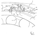
- a flame tube 2 of a combustion chamber of a fiber-reinforced ceramic ceramic material
- the combustion chamber is composed of an outer flame tube 2, an inner flame tube 8, and the combustion chamber head 7. Outer and inner flame tubes are divided circumferentially into three or more parts.
- the flame tube 2.8 is divided circumferentially into three or more parts.
- the individual segments are connected to each other by axial flanges 1, 9 by means of fastening elements 106.
- the holder of the outer flame tube 2 to a combustion chamber housing 3 is carried out with a hinged rigid support in the form of a chain link 104, which with the outer Axialflansch 1 am outer flame tube 2 and a projection 101 for attachment to the combustion chamber housing 3 is connected.
- the imaginary extensions 304 of the chain links 104 intersect on an engine axis 301 at an angle that is greater than 0 ° and less than 180 °.
- the outer flame tube 2 is guided on an angled bearing surface 208 and positioned. Depending on the design, the outer flame tube 2 can rest on the bearing surface 208, so that the holder allows a constant clamping force during operation, or it can be set to a desired cooling gap, which is held constant during operation by the holder.
- a flexible high temperature resistant sealing element 209 may additionally be positioned.
- connection between the flame tube 2,8 and combustion chamber head 7 is also via an articulated bracket 4, 204, which attaches both to the axial flange 1, 9 of the flame tube 2 and to a projection 103, 203 for attachment to the Brennschkopt 7.
- the extensions 302, 303 of the chain links 4, 204 intersect on the engine axis 301 at an angle which is greater than 0 ° and less than 180 °.
- the projections 103, 203 may be integrally formed or joined to the combustion chamber head 7.
- the projection 101 may be integrally formed or joined to the combustion chamber housing 3.
- hinged supports 4, 204 and the projections 103, 203 are independent of their shape.
- the connecting elements may be made of metallic or ceramic materials.
- the holder according to the invention makes it possible to move the ceramic housing at high temperatures stress-free relative to the combustion chamber housing and the combustion chamber head.
- the relative movements are intercepted by the articulated mounting of the flame tube.
- the segmentation of the flame tube makes it possible to keep the manufacturing costs low compared to a full-ring design, since the volume of an autoclave is better utilized by stacking the individual segments. Nevertheless, the introduction of the Axialflanschs no leaks, as in shingles after GB-A 1 450 894 are common, up.
- Fig. 6 shows a schematic overall view of a combustion chamber according to the invention in a gas turbine.
- a combustion chamber 401 a burner 402 with arm and head, bypass 403, fan 404, compressor 405, inner and outer combustion chamber housing 407 and 408, Turbinenleitrad 409, turbine runner 410, drive shaft 411 and 412 combustion chamber head are provided.
Landscapes
- Engineering & Computer Science (AREA)
- Chemical & Material Sciences (AREA)
- Combustion & Propulsion (AREA)
- Mechanical Engineering (AREA)
- General Engineering & Computer Science (AREA)
- Ceramic Engineering (AREA)
- Turbine Rotor Nozzle Sealing (AREA)
Claims (5)
- Arrangement avec une chambre de combustion annulaire de turbine à gaz pour un moteur, comprenant un tube à flamme (2, 8) pour l'essentiel cylindrique qui est fabriqué en un matériau céramique et subdivisé dans le sens circonférentiel en plusieurs éléments circonférentiels (10, 11, 12), les éléments circonférentiels (10, 11, 12) étant respectivement reliés par des brides axiales (1, 9), caractérisé en ce que les brides axiales (1, 9) sont respectivement logées au moyen d'éléments de couplage (4, 104, 204) articulés en forme de chaînon, et que des prolongements des lignes médianes (302, 303, 304) des éléments de couplage (4, 104, 204) coupent un axe du moteur (301).
- Arrangement selon la revendication n° 1, caractérisé en ce qu'une bride axiale (1) extérieure dans le sens radial du tube à flamme (2) extérieur est logée au moyen d'un élément de couplage (104) sur un carter extérieur (3) de la chambre de combustion.
- Arrangement selon la revendication n° 1, caractérisé en ce qu'une bride axiale (9) intérieure dans le sens radial du tube à flamme (8) intérieur est logée au moyen d'un élément de couplage sur un carter intérieur (205) de la chambre de combustion.
- Arrangement selon une des revendications n° 1 à n° 3, caractérisé en ce qu'une bride axiale (9) intérieure dans le sens radial du tube à flamme (8) intérieur est logée au moyen d'un élément de couplage (204) sur une tête (7) de la chambre de combustion.
- Arrangement selon une des revendications n° 1 à n° 4, caractérisé en ce qu'une bride axiale (1) extérieure dans le sens radial du tube à flamme (2) extérieur est logée au moyen de l'élément de couplage (4) sur une tête (7) de la chambre de combustion.
Applications Claiming Priority (1)
| Application Number | Priority Date | Filing Date | Title |
|---|---|---|---|
| DE102008010294A DE102008010294A1 (de) | 2008-02-21 | 2008-02-21 | Gasturbinenbrennkammer mit keramischem Flammenrohr |
Publications (3)
| Publication Number | Publication Date |
|---|---|
| EP2093487A2 EP2093487A2 (fr) | 2009-08-26 |
| EP2093487A3 EP2093487A3 (fr) | 2013-11-27 |
| EP2093487B1 true EP2093487B1 (fr) | 2016-08-17 |
Family
ID=40512449
Family Applications (1)
| Application Number | Title | Priority Date | Filing Date |
|---|---|---|---|
| EP09002226.0A Not-in-force EP2093487B1 (fr) | 2008-02-21 | 2009-02-17 | Arrangement avec une chambre de combustion de turbine à gaz avec un tube de flamme céramique pour un moteur |
Country Status (3)
| Country | Link |
|---|---|
| US (1) | US8281598B2 (fr) |
| EP (1) | EP2093487B1 (fr) |
| DE (1) | DE102008010294A1 (fr) |
Cited By (1)
| Publication number | Priority date | Publication date | Assignee | Title |
|---|---|---|---|---|
| DE102015226079A1 (de) * | 2015-12-18 | 2017-06-22 | Dürr Systems Ag | Brennkammervorrichtung und Gasturbinenvorrichtung |
Families Citing this family (8)
| Publication number | Priority date | Publication date | Assignee | Title |
|---|---|---|---|---|
| WO2014149108A1 (fr) | 2013-03-15 | 2014-09-25 | Graves Charles B | Agencement d'enceinte et de chemisage à dalles pour une chambre de combustion |
| US10100737B2 (en) | 2013-05-16 | 2018-10-16 | Siemens Energy, Inc. | Impingement cooling arrangement having a snap-in plate |
| RU2598964C2 (ru) * | 2014-12-12 | 2016-10-10 | Федеральное агентство научных организаций Федеральное Государственное Бюджетное Научное Учреждение Всероссийский научно-исследовательский институт электрификации сельского хозяйства (ФГБНУ ВИЭСХ) | Устройство камеры сгорания с регулируемым зазором подачи охлаждающего воздуха для микрогазотурбинного двигателя |
| US10533740B2 (en) | 2015-07-09 | 2020-01-14 | Carrier Corporation | Inward fired ultra low NOX insulating burner flange |
| CN205016725U (zh) * | 2015-09-10 | 2016-02-03 | 欧品电子(昆山)有限公司 | 电源插座端子 |
| US11015812B2 (en) * | 2018-05-07 | 2021-05-25 | Rolls-Royce North American Technologies Inc. | Combustor bolted segmented architecture |
| CN110107402B (zh) * | 2019-04-29 | 2021-06-08 | 中国航空工业集团公司金城南京机电液压工程研究中心 | 一种陶瓷涡轮发动机 |
| CN114484505B (zh) * | 2022-01-27 | 2023-05-16 | 西安鑫垚陶瓷复合材料有限公司 | 陶瓷基复合材料全环型火焰筒、定型模具及其制备方法 |
Family Cites Families (14)
| Publication number | Priority date | Publication date | Assignee | Title |
|---|---|---|---|---|
| US1346600A (en) * | 1913-10-10 | 1920-07-13 | Stock Motorpflug Gmbh | Moldboard for plows |
| GB543918A (en) * | 1939-09-29 | 1942-03-19 | Bbc Brown Boveri & Cie | Improvements and relating to combustion chambers |
| US2686655A (en) * | 1949-09-02 | 1954-08-17 | Maschf Augsburg Nuernberg Ag | Joint between ceramic and metallic parts |
| US3854503A (en) * | 1971-08-05 | 1974-12-17 | Lucas Industries Ltd | Flame tubes |
| GB1450894A (en) | 1972-11-01 | 1976-09-29 | Lucas Industries Ltd | Flame tubes |
| US3956886A (en) * | 1973-12-07 | 1976-05-18 | Joseph Lucas (Industries) Limited | Flame tubes for gas turbine engines |
| DE4114768A1 (de) * | 1990-05-17 | 1991-11-21 | Siemens Ag | Keramischer hitzeschild fuer eine heissgasfuehrende struktur |
| US5333443A (en) * | 1993-02-08 | 1994-08-02 | General Electric Company | Seal assembly |
| US5636508A (en) * | 1994-10-07 | 1997-06-10 | Solar Turbines Incorporated | Wedge edge ceramic combustor tile |
| DE59806717D1 (de) * | 1998-03-17 | 2003-01-30 | Alstom Switzerland Ltd | Keramische Auskleidung einer Brennkammer |
| US6397603B1 (en) | 2000-05-05 | 2002-06-04 | The United States Of America As Represented By The Secretary Of The Air Force | Conbustor having a ceramic matrix composite liner |
| US7665307B2 (en) * | 2005-12-22 | 2010-02-23 | United Technologies Corporation | Dual wall combustor liner |
| DE102006060857B4 (de) * | 2006-12-22 | 2014-02-13 | Deutsches Zentrum für Luft- und Raumfahrt e.V. | CMC-Brennkammerauskleidung in Doppelschichtbauweise |
| US7861535B2 (en) * | 2007-09-24 | 2011-01-04 | United Technologies Corporation | Self-aligning liner support hanger |
-
2008
- 2008-02-21 DE DE102008010294A patent/DE102008010294A1/de not_active Withdrawn
-
2009
- 2009-02-17 EP EP09002226.0A patent/EP2093487B1/fr not_active Not-in-force
- 2009-02-19 US US12/379,380 patent/US8281598B2/en not_active Expired - Fee Related
Cited By (1)
| Publication number | Priority date | Publication date | Assignee | Title |
|---|---|---|---|---|
| DE102015226079A1 (de) * | 2015-12-18 | 2017-06-22 | Dürr Systems Ag | Brennkammervorrichtung und Gasturbinenvorrichtung |
Also Published As
| Publication number | Publication date |
|---|---|
| US8281598B2 (en) | 2012-10-09 |
| DE102008010294A1 (de) | 2009-08-27 |
| EP2093487A2 (fr) | 2009-08-26 |
| EP2093487A3 (fr) | 2013-11-27 |
| US20090235667A1 (en) | 2009-09-24 |
Similar Documents
| Publication | Publication Date | Title |
|---|---|---|
| EP2093487B1 (fr) | Arrangement avec une chambre de combustion de turbine à gaz avec un tube de flamme céramique pour un moteur | |
| DE102011057077B4 (de) | Strukturelle Turbinenmantelringvorrichtung geringer Duktilität | |
| EP2527253B1 (fr) | Dispositif de dégivrage d'une turbine à gaz volatil | |
| EP2503246B1 (fr) | Tête de chambre de combustion segmentée | |
| EP2342427B1 (fr) | Support d'aubes statorique axialement segmenté d'une turbine à gaz | |
| DE102010016532A1 (de) | Turbinengehäuse mit Bolzenlagerung | |
| CH701279B1 (de) | Befestigungsanordnung für eine Brennkammerauskleidung und Gasturbinenmotor. | |
| EP2342425B1 (fr) | Turbine à gaz avec plaque de fixation entre la base d'aube et le disque | |
| DE102014219552A1 (de) | Leitschaufelverstellvorrichtung einer Gasturbine | |
| EP2617979B1 (fr) | Dispositif de dégivrage pour turbine à gaz | |
| CH705838A1 (de) | Abgasgehäuse für eine Gasturbine sowie Gasturbine mit einem Abgasgehäuse. | |
| DE1601677A1 (de) | Flammrohrkonstruktion fuer Gasturbinen | |
| DE102011016917A1 (de) | Gasturbinenbrennkammer mit einer Halterung einer Dichtung für ein Anbauteil | |
| EP2526263B1 (fr) | Système de boîtier pour une turbomachine axiale | |
| EP3176386B1 (fr) | Système de virole interne, virole interne, boîtier intermédiaire et turbomachine associés | |
| EP1724526A1 (fr) | Coquille de turbine à gaz, turbine à gaz et procédé de démarrage et d'arrêt d'une turbine à gaz | |
| EP1429077B1 (fr) | Turbine à gaz | |
| WO2004031656A1 (fr) | Turbine a gaz | |
| EP3921577B1 (fr) | Système de chambre de combustion à tubes et installation de turbine à gaz pourvue d'un tel système de chambre de combustion à tubes | |
| EP1529181B1 (fr) | Chambre de combustion de turbine a gaz | |
| EP1731715A1 (fr) | Transition d'une chambre de combustion à une turbine | |
| EP1744014A1 (fr) | Agencement de montage des aubes d'entrée d'une turbine à gaz | |
| EP3179169B1 (fr) | Procédé de montage d'une chambre de combustion d'une turbine à gaz | |
| EP2352909B1 (fr) | Support d'aubes directrices | |
| DE3309812C2 (de) | Äußeres Gehäuse für ein Gasturbinentriebwerk |
Legal Events
| Date | Code | Title | Description |
|---|---|---|---|
| PUAI | Public reference made under article 153(3) epc to a published international application that has entered the european phase |
Free format text: ORIGINAL CODE: 0009012 |
|
| AK | Designated contracting states |
Kind code of ref document: A2 Designated state(s): AT BE BG CH CY CZ DE DK EE ES FI FR GB GR HR HU IE IS IT LI LT LU LV MC MK MT NL NO PL PT RO SE SI SK TR |
|
| AX | Request for extension of the european patent |
Extension state: AL BA RS |
|
| PUAL | Search report despatched |
Free format text: ORIGINAL CODE: 0009013 |
|
| AK | Designated contracting states |
Kind code of ref document: A3 Designated state(s): AT BE BG CH CY CZ DE DK EE ES FI FR GB GR HR HU IE IS IT LI LT LU LV MC MK MT NL NO PL PT RO SE SI SK TR |
|
| AX | Request for extension of the european patent |
Extension state: AL BA RS |
|
| RIC1 | Information provided on ipc code assigned before grant |
Ipc: F23M 5/04 20060101ALI20131022BHEP Ipc: F23R 3/50 20060101ALI20131022BHEP Ipc: F23R 3/00 20060101AFI20131022BHEP |
|
| 17P | Request for examination filed |
Effective date: 20140430 |
|
| RBV | Designated contracting states (corrected) |
Designated state(s): AT BE BG CH CY CZ DE DK EE ES FI FR GB GR HR HU IE IS IT LI LT LU LV MC MK MT NL NO PL PT RO SE SI SK TR |
|
| AKX | Designation fees paid |
Designated state(s): DE FR GB |
|
| 17Q | First examination report despatched |
Effective date: 20150812 |
|
| GRAP | Despatch of communication of intention to grant a patent |
Free format text: ORIGINAL CODE: EPIDOSNIGR1 |
|
| INTG | Intention to grant announced |
Effective date: 20160419 |
|
| GRAS | Grant fee paid |
Free format text: ORIGINAL CODE: EPIDOSNIGR3 |
|
| GRAA | (expected) grant |
Free format text: ORIGINAL CODE: 0009210 |
|
| AK | Designated contracting states |
Kind code of ref document: B1 Designated state(s): DE FR GB |
|
| REG | Reference to a national code |
Ref country code: GB Ref legal event code: FG4D Free format text: NOT ENGLISH |
|
| RIN1 | Information on inventor provided before grant (corrected) |
Inventor name: SADIG, SERMED Inventor name: GERENDAS, MIKLOS, DR. |
|
| REG | Reference to a national code |
Ref country code: DE Ref legal event code: R096 Ref document number: 502009012956 Country of ref document: DE |
|
| REG | Reference to a national code |
Ref country code: DE Ref legal event code: R082 Ref document number: 502009012956 Country of ref document: DE Representative=s name: HOEFER & PARTNER PATENTANWAELTE MBB, DE Ref country code: DE Ref legal event code: R081 Ref document number: 502009012956 Country of ref document: DE Owner name: ROLLS-ROYCE DEUTSCHLAND LTD & CO KG, DE Free format text: FORMER OWNER: ROLLS-ROYCE DEUTSCHLAND & CO. KG, 15827 BLANKENFELDE, DE |
|
| REG | Reference to a national code |
Ref country code: FR Ref legal event code: PLFP Year of fee payment: 9 |
|
| PGFP | Annual fee paid to national office [announced via postgrant information from national office to epo] |
Ref country code: FR Payment date: 20170223 Year of fee payment: 9 Ref country code: DE Payment date: 20170227 Year of fee payment: 9 |
|
| REG | Reference to a national code |
Ref country code: DE Ref legal event code: R097 Ref document number: 502009012956 Country of ref document: DE |
|
| PGFP | Annual fee paid to national office [announced via postgrant information from national office to epo] |
Ref country code: GB Payment date: 20170227 Year of fee payment: 9 |
|
| PLBE | No opposition filed within time limit |
Free format text: ORIGINAL CODE: 0009261 |
|
| STAA | Information on the status of an ep patent application or granted ep patent |
Free format text: STATUS: NO OPPOSITION FILED WITHIN TIME LIMIT |
|
| 26N | No opposition filed |
Effective date: 20170518 |
|
| REG | Reference to a national code |
Ref country code: DE Ref legal event code: R119 Ref document number: 502009012956 Country of ref document: DE |
|
| GBPC | Gb: european patent ceased through non-payment of renewal fee |
Effective date: 20180217 |
|
| REG | Reference to a national code |
Ref country code: FR Ref legal event code: ST Effective date: 20181031 |
|
| PG25 | Lapsed in a contracting state [announced via postgrant information from national office to epo] |
Ref country code: DE Free format text: LAPSE BECAUSE OF NON-PAYMENT OF DUE FEES Effective date: 20180901 |
|
| PG25 | Lapsed in a contracting state [announced via postgrant information from national office to epo] |
Ref country code: FR Free format text: LAPSE BECAUSE OF NON-PAYMENT OF DUE FEES Effective date: 20180228 Ref country code: GB Free format text: LAPSE BECAUSE OF NON-PAYMENT OF DUE FEES Effective date: 20180217 |