EP2093492A2 - Dispositif d'appareil ménager - Google Patents
Dispositif d'appareil ménager Download PDFInfo
- Publication number
- EP2093492A2 EP2093492A2 EP09100116A EP09100116A EP2093492A2 EP 2093492 A2 EP2093492 A2 EP 2093492A2 EP 09100116 A EP09100116 A EP 09100116A EP 09100116 A EP09100116 A EP 09100116A EP 2093492 A2 EP2093492 A2 EP 2093492A2
- Authority
- EP
- European Patent Office
- Prior art keywords
- door
- domestic appliance
- unit
- spring
- torque
- Prior art date
- Legal status (The legal status is an assumption and is not a legal conclusion. Google has not performed a legal analysis and makes no representation as to the accuracy of the status listed.)
- Granted
Links
Images





Classifications
-
- F—MECHANICAL ENGINEERING; LIGHTING; HEATING; WEAPONS; BLASTING
- F24—HEATING; RANGES; VENTILATING
- F24C—DOMESTIC STOVES OR RANGES ; DETAILS OF DOMESTIC STOVES OR RANGES, OF GENERAL APPLICATION
- F24C15/00—Details
- F24C15/02—Doors specially adapted for stoves or ranges
- F24C15/024—Handles
-
- A—HUMAN NECESSITIES
- A47—FURNITURE; DOMESTIC ARTICLES OR APPLIANCES; COFFEE MILLS; SPICE MILLS; SUCTION CLEANERS IN GENERAL
- A47L—DOMESTIC WASHING OR CLEANING; SUCTION CLEANERS IN GENERAL
- A47L15/00—Washing or rinsing machines for crockery or tableware
- A47L15/42—Details
- A47L15/4251—Details of the casing
- A47L15/4257—Details of the loading door
- A47L15/4261—Connections of the door to the casing, e.g. door hinges
-
- D—TEXTILES; PAPER
- D06—TREATMENT OF TEXTILES OR THE LIKE; LAUNDERING; FLEXIBLE MATERIALS NOT OTHERWISE PROVIDED FOR
- D06F—LAUNDERING, DRYING, IRONING, PRESSING OR FOLDING TEXTILE ARTICLES
- D06F37/00—Details specific to washing machines covered by groups D06F21/00 - D06F25/00
- D06F37/02—Rotary receptacles, e.g. drums
- D06F37/04—Rotary receptacles, e.g. drums adapted for rotation or oscillation about a horizontal or inclined axis
- D06F37/10—Doors; Securing means therefor
-
- F—MECHANICAL ENGINEERING; LIGHTING; HEATING; WEAPONS; BLASTING
- F24—HEATING; RANGES; VENTILATING
- F24C—DOMESTIC STOVES OR RANGES ; DETAILS OF DOMESTIC STOVES OR RANGES, OF GENERAL APPLICATION
- F24C15/00—Details
- F24C15/02—Doors specially adapted for stoves or ranges
- F24C15/022—Latches
-
- F—MECHANICAL ENGINEERING; LIGHTING; HEATING; WEAPONS; BLASTING
- F24—HEATING; RANGES; VENTILATING
- F24C—DOMESTIC STOVES OR RANGES ; DETAILS OF DOMESTIC STOVES OR RANGES, OF GENERAL APPLICATION
- F24C15/00—Details
- F24C15/02—Doors specially adapted for stoves or ranges
- F24C15/026—Doors specially adapted for stoves or ranges stowing of door in open position
-
- A—HUMAN NECESSITIES
- A47—FURNITURE; DOMESTIC ARTICLES OR APPLIANCES; COFFEE MILLS; SPICE MILLS; SUCTION CLEANERS IN GENERAL
- A47L—DOMESTIC WASHING OR CLEANING; SUCTION CLEANERS IN GENERAL
- A47L15/00—Washing or rinsing machines for crockery or tableware
- A47L15/42—Details
- A47L15/4251—Details of the casing
- A47L15/4274—Arrangement of electrical components, e.g. control units or cables
Definitions
- the invention relates to a domestic appliance device according to the preamble of claim 1.
- a home appliance device with a cable whose first end is directly connected to a first spring and whose second end is indirectly connected to a second spring and which transmits a torque in an operating state, is known.
- One of the springs is deflected in the transmission of torque, while the remaining spring ensures a tension of the cable with a constant force.
- the object of the invention is in particular to provide a generic device with improved properties in terms of a simple design.
- the invention relates to a domestic appliance device having at least one door unit, which at least one door handle, which is rotatably mounted about an axis, at least one torque transmitting means, which transmits at least one torque in at least one operating state in cooperation with the door handle, a first spring means, which at least attached to a mounting portion of a fastening means of the door unit, which is immovable in at least one operating sequence relative to the axis, and at least one second spring means, which is attached at least to a mounting region of a fastening means of the door unit comprises.
- a "fastening region" of a fastening means, to which a spring means is fastened, is to be understood, in particular, as a region of the fastening means to which the fastening means touches the spring means and / or on which Spring means transmits a force to the fastener.
- a “torque transmission means” is to be understood in particular a means which transmits torque in at least one operating state to a unit and / or a component.
- An “operating procedure” is to be understood in particular as meaning a sequence and / or a process in which the torque transmission means moves relative to the axis.
- first and the second spring means are fastened to the same fastening means of the door unit. As a result, components can be saved.
- the domestic appliance device has at least one functional means on which the torque transmission means is positively secured in at least one operating state.
- a functional means is meant in particular a bearing means, guide means, holding means and / or drive means.
- a “bearing means” is to be understood in particular as a rolling bearing means and / or a sliding bearing means.
- a “holding means” is to be understood in particular as meaning a means which, in at least one state of use, receives at least one load and transmits it to a supporting building means.
- drive means is meant in particular a means which transmits a drive from one means to another means.
- a “drive” should be understood in particular a rotary drive and / or a linear drive. This can be a simple installation can be achieved.
- the domestic appliance device has at least one locking unit which can be locked by the torque transmitted to the functional means. As a result, other components can be saved.
- the functional means is provided to rotatably support the door unit. In this way, a simple construction can be achieved.
- the functional means is provided to cause a change in the deflections of both spring means in an operating sequence in which the door unit is rotated. This can be achieved in a simple construction, an advantageous operation of the spring means.
- the domestic appliance device has at least one pane fastening means to which at least one of the spring means is fastened in at least one operating state. In this way, a simple construction can be achieved.
- the first spring means have a spring force that is many times greater than the second spring means.
- the spring stiffness of the first spring means is at least twice as large, in particular at least five times as large and particularly advantageously twenty times as great Spring hardness of the second spring means. This allows a user to operate the door handle in a comfortable manner, in particular when opening or closing the door unit. In particular, when the door unit is closed, the first spring means brings the door handle into a position in which the door handle is located when the door unit is closed.
- the door unit is closed in an operating state in which the first spring means has a smallest deflection.
- the spring means has a "smallest" deflection in an operating state, should be understood in particular that the spring means in the operating state has a smaller deflection than in all other operating states.
- the spring means can store energy when opening the door unit.
- the torque transmission means has at least one cable pull. This allows a cost-effective and stable construction can be achieved.
- the domestic appliance device has at least one storage space in which the unit is introduced in at least one state of use at least to a large extent.
- the home appliance door "for the most part" in the storage space is introduced, should be understood in particular that at least a portion of the appliance door, which forms at least sixty percent, in particular at least seventy-five percent and more preferably at least ninety percent of a vertical extension of the appliance door in a closed state in an operating position, is arranged in the storage space In this way, a compact arrangement can be achieved.
- the home appliance device has at least one door storage unit, which is provided to introduce the door unit by means of a sliding movement to a large extent in a storage space.
- a simple Verstaules the door unit can be achieved.
- FIG. 1 shows a household appliance 26 formed by an oven with a domestic appliance device having a pivotally mounted in pivoting directions 10, 12 household appliance door 14 with a door handle 62, which is shown in a disconnected state.
- the household appliance 26 has an oven muffle 30, which is arranged in a household appliance housing 28 and encloses a usable space 16 formed by a cooking chamber on five sides.
- the useful space 16 can be closed by the appliance door 14.
- the household appliance 26 a below the oven muffle 30 arranged storage space 18, in which the household appliance door 14 guided via a door storage unit 20 of the home appliance device is largely retractable by means of a pivoting movement and a subsequent sliding movement in a horizontal direction.
- the door storage unit 20 has two basically corresponding, each with lateral end faces of the appliance door 14 in the pivoting directions 10, 12 fixed and in a surface extension 22 of the appliance door 14 movably coupled guide means 24 with two rollers 171, 173, wherein only one of the two guide means 24 is shown.
- the surface extension 22 extends in closed home appliance door 14 in a vertical direction when the domestic appliance 26 is arranged in an operating position.
- the door storage unit 20 for receiving a portion of the weight of the appliance door 14 a relative to the appliance housing 28 movably mounted storage unit 38.
- FIG. 2 In addition to a door unit 64 with the door handle 62, the domestic appliance door 14 for transmitting the part of the weight of a coupling unit 34 with a contact portion 36 which the domestic appliance door 14 in an assembled state with the storage unit 38th coupled.
- the door unit 64 has an outer surface 32, which laterally delimits the domestic appliance door 14 in an operating position and in particular in a closed state of the appliance door 14 and when the household appliance door 14 is pushed into the storage space 18 in a horizontal direction.
- the contact region 36 is arranged.
- the contact region 36 is formed by an end section 56 of the axis unit 54 (FIG. FIG. 2 ).
- the bearing units 68 have elevations 72 with flat surface parts 74, which extend mainly in a direction perpendicular to the axis 76.
- a surface of the projections 72 and in particular the surface parts 74 form the contact region 36.
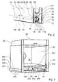
- FIG. 3 shows a schematic representation of the household appliance 26 without the appliance door 14 in a lateral frontal view.
- the bearing unit 38 is movably supported by two guide slots 44 of the household appliance 26 relative to the domestic appliance housing 28.
- the guide slots 44 which are formed mirror-inverted to each other, limit a portion of the storage space 18 in a front view of the domestic appliance on a right and a left side.
- the torque transmission means 48, 50 each have a receiving area 40, which in a mounted state of the appliance door 14, the elevations 72 of the storage units 68th and thus the contact areas 36 receives.
- the receiving region 40 is partially delimited by a contact surface 49 of the torque-transmitting means 48, 50, which rests against the contact region 36 in an assembled state of the appliance door 14 and transmits a torque to the contact region 36 and thus the coupling unit 34, which occurs when the appliance door 14 moves on the coupling unit 34 exerts a torque by which the coupling unit 34 is rotated relative to the door unit 64.
- the elevations 72 ( FIG. 2 ) as bearing means 86 by transmitting a portion of the weight of the appliance door 14 and the door unit 64 to the abutment surface 49 and to a lower confining surface 80 of the torque transmitting means 48, 50 which partially defines the receiving region 40 in the vertical downward direction.
- the torque transmission means 48, 50 thus function as holding means 90, which in particular hold the closed household appliance door 14 in position.
- the door unit 64 is designed as a profiled rail door and has two profiled rails 121, 123.
- the bearing units 68 are partially arranged in recesses 163 of the profile rails 121, 123.
- the recesses 163 are bounded by non-illustrated bearing surfaces of the rails 121, 123.
- the sliding bearing surfaces 84 of the bearing units 68 slide against the corresponding bearing surfaces of the profiled rails 121, 123.
- the rollers 111, 113 and thus the door handle 62 are rotatably supported by means of the profiled rails 121, 123.
- On the profile rails 121, 123 each one fastening means 98 is fixed relative to the rails 121, 123 immovably.
- An eyelet 125 of the fastener 98 which is integrally formed and, in a fully assembled state, functions as a disc attachment means for the inner disc 141 and the washer, has first and second attachment portions 100, 104 which are immovable relative to the axle 92.
- the door unit 64 also has a first and a second spring means 96, 102, which are formed as coil springs.
- a first end of the first spring means 96 is hooked to the first attachment portion 100, a first end of the second spring means 102 is hooked to the second attachment portion 104.
- At two ends of the cable 181 eyelets 117, 119 of the torque transmission means 94, 95 are further attached.
- a second end of the spring means 96 is further attached to the eyelet 117.
- the spring means 96 is disposed between the eyelet 125 and the roller 113.
- a second end of the second spring means 102 is attached to the eyelet 119.
- the second spring means 102 is disposed between the eyelet 125 and the bearing unit 68.
- Main extension directions of the spring means 96, 102 are parallel to the surface extension 22.
- a portion 129 of the torque transmitting means 94 which is attached to the eyelet 117, runs parallel and directly adjacent to an outer disk 133 of the door unit 64.
- a second section 131 extends parallel to the first section 129 and parallel to the inner pane 141 of the door unit 64 and is arranged directly next to the inner pane 141.
- the partial section 129 is arranged between the partial section 131 and the outer plate 133.
- FIG. 8 schematically shows the closed state of the appliance door 14.
- the first spring means 96 has in this case compared to all other possible operating positions a smallest deflection.
- a main extension direction 135 of the door handle 62 perpendicular to the axis 92 is in this case arranged perpendicular to the subsections 129, 131 and to the outer disk 133.
- the bearing units 68 remain stationary when opening the appliance door 14 relative to the bearing unit 38 and rotate relative to the rails 121, 123 about the axis 76.
- the bearing units 68 transmit thereby by means of the receiving portion 116 and the bolt 115, a torque and thus a drive to the torque transmission means 94, 95, which is why the bearing unit 68 is identical to a trained as a drive means 60 functional means 106.
- the torque transmitting means 94, 95 and the rollers 111, 113 transfer the drive to the door handle 62, which causes the main extension direction 135 of the door handle in each opening position of the door unit 64 to extend substantially in a horizontal direction when the domestic appliance 26 is in an operating position is arranged.
- the spring means 96 is stretched as the spring means 102 contracts.
- the storage unit 68 and the torque transmitting means 48 form a locking unit 108.
- the locking unit 108 is in FIG a release state ( FIG. 10 ), in which the appliance door 14 in a partially open position of the storage unit 38 can be decoupled when the surface extension 22 (see FIG. 1 ) includes an angle of about twenty degrees with a vertical.
- the surface extension 22 see FIG. 1
- a user or a fitter can the home appliance door 14 on outer surfaces 183 of the rails 121, 123, which surfaces of the rails 121, 123 and the home appliance door 14 in a front view partially limit laterally, and on outer surfaces 185, 187 of the inner pane 141 and the Outer disk 133, which partially laterally delimit the outer disk 133 and the inner disk 141 in the front view, and hold the household appliance door 14 in a straight line in the direction of the surface extension 22 upwards.
- the elevations 72 slide through indentations 162 of the torque transmission means 48, 50 (FIG. FIG. 5 ) and are thereby removed from the receiving areas 40, whereby the household appliance door 14 is disconnected from the storage unit 38.
- the bearing unit 38 can optionally be detected by a locking unit 161 in a position in which the bearing unit 38 is arranged immediately before uncoupling. If this option is used, after disconnecting the household appliance door 14, guide surfaces 143, 145 of the storage unit 38 facilitate coupling the household appliance door 14 to the storage unit 38, by guiding the raised portions 72 when introduced into the receiving area 40 and thus also the storage units 68. Furthermore, in the coupling operation, the rollers 171, 173 of the guide means 24 (see FIG FIG. 1 ) in lateral grooves 175 of the household appliance door 14, which partially delimit the household appliance door 14 in an operating position laterally ( FIG. 2 ).
- a groove bottom 177 of the groove 175 has a recess 179, in which the elevation 72 is arranged.
- the locking unit 108 is further provided to prevent removal of the appliance door 14 from the storage unit 38 in an at least partially open position of the appliance door 14.
- a user or a fitter brings the appliance door 14 in a position in which the surface extension 22 forms an angle of about twenty degrees with a vertical, and moves the door handle 62 in the direction of the surface extension 22, the door handle 62 rotates by means a coupling unit 139, which is formed by the rollers 111, 113, the torque transmission means 94, 95 and the bolts 115, the bearing units 68 relative to the rails 121, 123 about the axis 76.
- the protrusions 72 move to a locking position (FIG. FIG.
- undercuts 147 of the torque transmitting means 48, 50 which are formed by formed by the torque transmission means 48, 50 boundaries of the receiving areas 40, screwing.
- the screwing in of the elevations 72 is guided by guide surfaces 157, 159 which are formed by the receiving areas 40 delimiting surface parts of the torque transmission means 48, 50.
- One of the guide surfaces 159 is formed by the undercut 147.
- the screwing in of the elevations 72 is stopped in that two surface parts 149, 151 of the elevations 72 abut against two surface parts 153, 155 of the torque transmission means 48, which partially delimit the receiving region 40.
- the projections 72 are in the locking position. If a user then attempts to move the appliance door 14 in the direction of the surface extension 22 away from the storage unit 38, this is prevented by the projections 72 abutting the undercuts 147, as a result of which the projections 72 remain in the receiving areas 40.
- FIG. 12 shows a schematic representation of the appliance door 14 in an open position with the inner pane 141, which the utility space 16 (see FIG. 1 ) closes in a closed position of the appliance door 14.
- the protrusions 72 are inserted into the receiving areas 40 and the locking unit 108 is in the unlocked state. If an operator attempts to decouple the appliance door 14 from the storage unit 38 in the open position by attempting to guide the elevations 72 out of the receiving areas 40 through the indentations 162, then the outer pane 133 acts as a locking element, since the torque transmission means 48, 50 contact the Outer disk abut and this prevents removal of the projections 72 from the receiving areas 40.
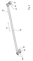
- the bearing units 68 are attached to the ends of the steel rod 66 and compressed so far until the bearing units 68 abut the ends of the steel rod 66. A first of the bearing units 68 is then inserted into one of the recesses 163 of one of the profile rails 121, 123. By means of a movement of the second of the bearing units 68 and a movement of the steel rod 66, the second bearing unit 68 is inserted into the remaining recess. The steel bar 66 and the bearing units 68 are then in their mounted position.
- the bearing units 68 each have a recess 165.
- one of the bearing units 68 is fastened by means of the steel clamp and the other bearing unit 68 is fastened in another way to the steel rod 66 or is formed integrally therewith.
- a further alternative possibility for fastening the bearing units 68 by means of the steel clamps would also be to arrange in receiving areas of the bearing units 68, in which the steel rod 66 is inserted in an assembled state, spring elements, such as compression springs, which upon compression of the bearing units 68 be compressed. By compressing these spring elements, an assembly of the coupling unit 34 is possible even with already glued rails 121, 123 by the bearing units 68 compressed and the spring elements are thus compressed.
- the bearing units 68 In an assembled state, the bearing units 68 would be pushed apart from these spring elements and thus attached to the rails 121, 123.
- the steel bar 66 could also have a different number of edges.
- the steel rod 66 can also be designed to be round, in which case the bearing units 68 would be rotatable relative to each other about the axis 76. In one embodiment of the coupling unit 34 without the steel rod 66, the bearing units 68 would otherwise be attached to the rails 121, 123.
- the locking unit 161 is provided to fix the home appliance door storage unit 191 in a pivotal position.
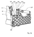
- the locking unit 161 has a locking means 195 designed as a bolt and an elastic actuating means 197, which is provided for locking the locking means 195 from a starting position (FIG. FIG. 13 ) in a locking position ( FIG. 14 ) in which the locking means detects the home appliance door bearing unit 191 in the pivotal position.
- the actuating means 197 is designed as an adjusting bracket.
- the locking means 195 engages a recess 201 of a locking means 200 of the locking unit 161, which is fixed to the guide means 24, that the guide means 24 and the locking means 200 relative to each other about an axis 204 which is parallel to the axis 193 and is rotated at a rotation of the guide means 24 with the guide means 24 are rotatable.
- the locking means 195 is with respect to the directions of rotation about the axis 193 on a housing-fixed guide member 203 (see FIG. 16 ) of the home appliance device. Therefore, when the locking means 195 is in the locking position, rotation of the guide means 24 about the axis 193 is prevented and the guide means 24 is thus fixed in a certain rotational position.
- the locking means 200 is provided to transmit a spring force to the guide means 24.
- a coil spring 207 is mounted, which is expanded upon opening of the appliance door 14 and a part of the potential energy, which the appliance door 14 has in a closed state, stores and thus serves as an energy storage unit.
- the torque transmission means 48, 50 are also parts of the domestic appliance door storage unit 191. They each have a recess 205 (FIG. FIG. 5 ) into which a locking means 189 (FIG. FIG. 1 ) of the guide means 24 in pivotal positions of the appliance door 14 and in particular in a pivot position of the appliance door 14, in which the locking means 195 is arranged in the locking position, engages.
- the guide means 24 and the bearing unit 38 are substantially immovable relative to each other. Accordingly, if the locking means 195 is in the locking state in a mounted state of the domestic appliance, the domestic appliance door storage unit 191 is fixed in a take-out swinging position. In this pivoting position, the domestic appliance door 14 can be decoupled from the domestic appliance door storage unit 191 by the rectilinear movement in the direction of the surface extension 22.
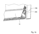
- an operator or fitter for fixing the appliance door storage unit 191 for example with the aid of a coin, can insert into a groove 206 of an actuating means 199 (FIG. FIG. 15 ), which is designed as a pivot, the locking unit 161 penetrate and this starting from a starting position, in which an opening and closing of the appliance door 14 is possible to rotate by ninety degrees ( Figures 13 and 14 ). If the home appliance door storage unit 191 is in a swing position different from the take-off swing position, the actuator 197 is cocked and thereby expanded by this rotation of the operation means 199 since the operation means 197 is fixed to the operation means 199.
- the home appliance door 14 can be decoupled by the linear movement of the bearing unit 38 and the guide means 24. Will a user the disconnected household appliance door 14 in an operating position such. B. bring in the closed position, the rollers 171, 173 are introduced into the groove 175 and the projections 72 in the receiving areas 40 and the actuating means 199 again turned back by one hundred eighty degrees, whereby the locking means 195 is moved back to the starting position and the appliance door 14 is pivotable, for example, in the closed position.
- FIG. 16 shows a portion of the home appliance device with the fixed to the housing guide member 203 to which the guide means 24 is rotatably mounted about the axis 193.
- the guide element 203 has slots formed as recesses 208, which the locking means 195 during the displacement of the starting position ( FIG. 13 ) in the locking position ( FIG. 14 ) and back again.
- the home appliance 26 further includes a home appliance door guide device.
- FIG. 17 shows an integrally formed first door guide means 209 of the household appliance door guide device.
- the household appliance 26 has a further door guide means 209, which is mirror-inverted compared to the first door guide means 209.
- the two door guide means 209 limit in a frontal view of the household appliance, the storage space 18 laterally (see FIG. 3 ).
- the door guide means 209 each form a guide slot, which is identical to the guide slot 44 or is mirror-inverted to this and which has a guide surface made of plastic with long glass fibers 210 for guiding the bearing unit 38.
- the guide slot 44 has a plurality of areas 256, 258, 260, which limit the storage space 18 partially laterally in an assembled state of the domestic appliance.
- the first area 256 is arranged on a front area of the household appliance and runs obliquely upward in an operating position of the household appliance.
- the second area 258 is arranged in a middle area 258 of the domestic appliance between the front area and the rear side of the household appliance and runs in a horizontal direction.
- the third area 260 limits the storage space 18 in a rear area partially laterally and extends obliquely downwards.
- the domestic appliance door guide device When introducing the household appliance door 14 into the storage space 18, the domestic appliance door 14 is at least partially braked by the household appliance door guide device.
- the domestic appliance door guide device has a damping means 212 ( FIG. 3 ), which is formed from a cuboid formed of polyurethane.
- the door guide means 209 At an end region of the guide slot 44 facing the rear of the household appliance, the door guide means 209 has a receiving area 214.
- the damping means 212 is engaged on a latching means 216 of the door guide means 209, which is arranged in the receiving region 214, and is partially arranged in the receiving region 214.
- the torque transmission means 50 see FIG. 4
- the damping means 212 transmits kinetic energy to the damping means 212, which partially converts the energy into heat and partially passes it on to the door guide means 209, which is thereby slightly deformed.
- a portion of the door guide means 209 partially surrounding the guide slot 44 has a rib structure 218 formed by a honeycomb cell pattern 230. Furthermore, the door guide means 209 forms a receiving area 228 which directly adjoins a front side of the storage space. In a mounted state is in the Receiving portion 228, the actuating means 199 arranged and rotatably supported by the door guide means 209 (see FIG. 15 ).
- the bearing means 222 could have a margin in a lateral, horizontal direction away from the storage space 18 in comparison to a new state of the domestic appliance. Due to a sliding surface 220 ( FIG. 18 ) of the door guide means 209, the bearing means 222 despite the margin perform a safe rotational movement. In this case, an outer region 234 of the bearing means 222 slides on the sliding surface 220 (FIG. FIG. 19 ), wherein the bearing means 222 is supported by the sliding surface 220.
- the sliding surface 220 is a segment of a cylinder jacket whose axis of symmetry corresponds to the axis 193.
- the door guide means 209 On one side of the door guide means 209, which in an assembled state faces an outer region of the domestic appliance, the door guide means 209 has a fastening means 224 for fastening a cable 236 to a lighting of the domestic appliance ( FIG. 20 ).
- the fastening means 224 is designed as a clamping means and clamps the cable 236 in a mounted state on the rib structure 218.
- Parts of the household appliance housing 28 are screwed directly to the door guide means 209 ( FIG. 3 ). These are in particular a floor 238, side walls 240, an intermediate floor 242, which limits the storage space 18 partially upwards, a trim panel and a Lisene.
- the bottom 238 has a fold 244, which expands in an operating position upwards and surrounds the door guide means 209.
- the fold 244 is screwed to the door guide means 209 at three points 246.
- the three points 246 are evenly distributed over a depth dimension of the household appliance.
- the door guide means 209 has an indentation at one end section of the guide slot 44, through which the bearing unit 38 can be removed from the guide slot 44. Before such removal of the bearing unit 38, the coupling of the bearing unit 38 with the locking means 189 designed as a tooth must be canceled.
- the door guide means 209 has an elevation 254 ( FIG. 17 ), which engages in a mounted state in the drip groove 250.
Landscapes
- Engineering & Computer Science (AREA)
- Chemical & Material Sciences (AREA)
- Combustion & Propulsion (AREA)
- Mechanical Engineering (AREA)
- General Engineering & Computer Science (AREA)
- Textile Engineering (AREA)
- Power-Operated Mechanisms For Wings (AREA)
- Support Devices For Sliding Doors (AREA)
- Electric Ovens (AREA)
Applications Claiming Priority (1)
| Application Number | Priority Date | Filing Date | Title |
|---|---|---|---|
| DE102008010525A DE102008010525A1 (de) | 2008-02-22 | 2008-02-22 | Hausgerätvorrichtung |
Publications (3)
| Publication Number | Publication Date |
|---|---|
| EP2093492A2 true EP2093492A2 (fr) | 2009-08-26 |
| EP2093492A3 EP2093492A3 (fr) | 2014-04-02 |
| EP2093492B1 EP2093492B1 (fr) | 2016-04-13 |
Family
ID=40639781
Family Applications (1)
| Application Number | Title | Priority Date | Filing Date |
|---|---|---|---|
| EP09100116.4A Active EP2093492B1 (fr) | 2008-02-22 | 2009-02-17 | Dispositif d'appareil ménager |
Country Status (2)
| Country | Link |
|---|---|
| EP (1) | EP2093492B1 (fr) |
| DE (1) | DE102008010525A1 (fr) |
Cited By (7)
| Publication number | Priority date | Publication date | Assignee | Title |
|---|---|---|---|---|
| EP2581666A1 (fr) * | 2011-10-11 | 2013-04-17 | BSH Bosch und Siemens Hausgeräte GmbH | Porte pour un appareil ménager, appareil ménager équipé d'une porte et procédé de déplacement de la poignée de porte d'un appareil ménager |
| US20140035453A1 (en) * | 2012-08-02 | 2014-02-06 | Hongsik Kwon | Home Appliance Having Movable Door Handle |
| US20160091209A1 (en) * | 2014-09-26 | 2016-03-31 | Lg Electronics Inc. | Cooking Appliance |
| EP2740871A3 (fr) * | 2012-12-04 | 2016-05-18 | BSH Hausgeräte GmbH | Dispositif destiné à un appareil ménager comprenant une charnière et un dispositif de couplage et appareil ménager doté d'un tel dispositif |
| CN111246787A (zh) * | 2017-10-17 | 2020-06-05 | Bsh家用电器有限公司 | 家用电器 |
| US11136798B2 (en) * | 2016-12-08 | 2021-10-05 | Samsung Electronics Co., Ltd. | Home appliance having leveling door handle |
| EP3658824B1 (fr) * | 2017-07-28 | 2023-11-01 | BSH Hausgeräte GmbH | Appareil de cuisson muni d'une porte escamotable qui présente un ressort de retenue spécifique pour un coussinet de palier |
Families Citing this family (2)
| Publication number | Priority date | Publication date | Assignee | Title |
|---|---|---|---|---|
| DE102015206576A1 (de) * | 2015-04-13 | 2016-10-13 | BSH Hausgeräte GmbH | Haushaltsgerät mit einer in einem Verstauraum versenkbaren Tür mit spezifischer Lagereinheit |
| DE102024209734A1 (de) | 2024-10-04 | 2026-04-09 | BSH Hausgeräte GmbH | Öffnen eines Deckels einer Wärmebehandlungsschublade |
Family Cites Families (5)
| Publication number | Priority date | Publication date | Assignee | Title |
|---|---|---|---|---|
| US2833270A (en) * | 1952-04-05 | 1958-05-06 | Wrought Iron Range Company | Oven door hinge assembly |
| DE4344337A1 (de) * | 1993-12-23 | 1995-06-29 | Bosch Siemens Hausgeraete | Schwenkbar gelagerte Tür, insbesondere für Haushaltsgeräte |
| DE10208490A1 (de) * | 2002-02-27 | 2004-02-05 | BSH Bosch und Siemens Hausgeräte GmbH | Haushaltsgerät |
| DE102004006764A1 (de) * | 2004-02-11 | 2005-09-08 | BSH Bosch und Siemens Hausgeräte GmbH | Tür |
| DE102004059563A1 (de) * | 2004-12-10 | 2006-02-23 | Miele & Cie. Kg | Haushaltsgerät mit einem Korpus und einer daran um eine Schwenkachse schwenkbar gehaltenen Tür mit einem Türgriff |
-
2008
- 2008-02-22 DE DE102008010525A patent/DE102008010525A1/de not_active Withdrawn
-
2009
- 2009-02-17 EP EP09100116.4A patent/EP2093492B1/fr active Active
Cited By (12)
| Publication number | Priority date | Publication date | Assignee | Title |
|---|---|---|---|---|
| EP2581666A1 (fr) * | 2011-10-11 | 2013-04-17 | BSH Bosch und Siemens Hausgeräte GmbH | Porte pour un appareil ménager, appareil ménager équipé d'une porte et procédé de déplacement de la poignée de porte d'un appareil ménager |
| US20140035453A1 (en) * | 2012-08-02 | 2014-02-06 | Hongsik Kwon | Home Appliance Having Movable Door Handle |
| US9138056B2 (en) * | 2012-08-02 | 2015-09-22 | Lg Electronics Inc. | Home appliance having movable door handle |
| EP2740871A3 (fr) * | 2012-12-04 | 2016-05-18 | BSH Hausgeräte GmbH | Dispositif destiné à un appareil ménager comprenant une charnière et un dispositif de couplage et appareil ménager doté d'un tel dispositif |
| US20160091209A1 (en) * | 2014-09-26 | 2016-03-31 | Lg Electronics Inc. | Cooking Appliance |
| US10443857B2 (en) * | 2014-09-26 | 2019-10-15 | Lg Electronics Inc. | Cooking appliance |
| US11054143B2 (en) | 2014-09-26 | 2021-07-06 | Lg Electronics Inc. | Cooking appliance |
| US11946648B2 (en) | 2014-09-26 | 2024-04-02 | Lg Electronics Inc. | Cooking appliance |
| US11136798B2 (en) * | 2016-12-08 | 2021-10-05 | Samsung Electronics Co., Ltd. | Home appliance having leveling door handle |
| EP3658824B1 (fr) * | 2017-07-28 | 2023-11-01 | BSH Hausgeräte GmbH | Appareil de cuisson muni d'une porte escamotable qui présente un ressort de retenue spécifique pour un coussinet de palier |
| CN111246787A (zh) * | 2017-10-17 | 2020-06-05 | Bsh家用电器有限公司 | 家用电器 |
| CN111246787B (zh) * | 2017-10-17 | 2023-04-07 | Bsh家用电器有限公司 | 家用电器 |
Also Published As
| Publication number | Publication date |
|---|---|
| EP2093492A3 (fr) | 2014-04-02 |
| EP2093492B1 (fr) | 2016-04-13 |
| DE102008010525A1 (de) | 2009-08-27 |
Similar Documents
| Publication | Publication Date | Title |
|---|---|---|
| EP2093492B1 (fr) | Dispositif d'appareil ménager | |
| EP1979684B1 (fr) | Appareil ménager | |
| EP1481142B1 (fr) | Appareil electromenager et porte d'appareil electromenager | |
| EP2093495B1 (fr) | Dispositif de commande de porte d'appareil ménager | |
| EP2189725A2 (fr) | Dispositif d'appareil ménager | |
| EP1481198B1 (fr) | Appareil menager | |
| EP2093493B1 (fr) | Dispositif d'appareil ménager | |
| EP1481141B1 (fr) | Appareil domestique et porte d'appareil domestique | |
| EP1481197B1 (fr) | Appareil menager | |
| EP2362050A2 (fr) | Dispositif de charnière, appareil ménager doté d'une porte et procédé de rééquipement d'un amortisseur | |
| EP1481199B1 (fr) | Appareil menager et procede de fabrication d'un appareil menager | |
| EP2093496B1 (fr) | Dispositif d'appareil ménager | |
| DE102008010498B4 (de) | Hausgerätvorrichtung | |
| EP2806769B1 (fr) | Système de rétraction pour une pluralité d'éléments de meuble coulissants | |
| EP2093494B1 (fr) | Dispositif d'appareil ménager | |
| EP3143227B1 (fr) | Ensemble de palier pour une porte | |
| WO2017055340A1 (fr) | Ferrure pour porte coulissante et procédé de montage d'une porte coulissante | |
| DE102005002822B4 (de) | Türscharnier für ein Haushaltsgerät | |
| EP4448905A1 (fr) | Ensemble de suspension pour porte coulissante | |
| CH701926B1 (de) | Drehflügeltürantrieb mit Kurvenscheibe. | |
| DE10208473B4 (de) | Haushaltsgerät | |
| DE102019214760B4 (de) | Schutzvorrichtung für einen Kraftfahrzeuginnenraum |
Legal Events
| Date | Code | Title | Description |
|---|---|---|---|
| PUAI | Public reference made under article 153(3) epc to a published international application that has entered the european phase |
Free format text: ORIGINAL CODE: 0009012 |
|
| AK | Designated contracting states |
Kind code of ref document: A2 Designated state(s): AT BE BG CH CY CZ DE DK EE ES FI FR GB GR HR HU IE IS IT LI LT LU LV MC MK MT NL NO PL PT RO SE SI SK TR |
|
| AX | Request for extension of the european patent |
Extension state: AL BA RS |
|
| PUAL | Search report despatched |
Free format text: ORIGINAL CODE: 0009013 |
|
| AK | Designated contracting states |
Kind code of ref document: A3 Designated state(s): AT BE BG CH CY CZ DE DK EE ES FI FR GB GR HR HU IE IS IT LI LT LU LV MC MK MT NL NO PL PT RO SE SI SK TR |
|
| AX | Request for extension of the european patent |
Extension state: AL BA RS |
|
| RIC1 | Information provided on ipc code assigned before grant |
Ipc: A47L 15/42 20060101ALI20140225BHEP Ipc: F25D 23/02 20060101ALI20140225BHEP Ipc: F24C 15/02 20060101AFI20140225BHEP Ipc: D06F 37/10 20060101ALI20140225BHEP |
|
| 17P | Request for examination filed |
Effective date: 20141002 |
|
| RBV | Designated contracting states (corrected) |
Designated state(s): AT BE BG CH CY CZ DE DK EE ES FI FR GB GR HR HU IE IS IT LI LT LU LV MC MK MT NL NO PL PT RO SE SI SK TR |
|
| AKX | Designation fees paid |
Designated state(s): AT BE BG CH CY CZ DE DK EE ES FI FR GB GR HR HU IE IS IT LI LT LU LV MC MK MT NL NO PL PT RO SE SI SK TR |
|
| AXX | Extension fees paid |
Extension state: AL Extension state: BA Extension state: RS |
|
| RAP1 | Party data changed (applicant data changed or rights of an application transferred) |
Owner name: BSH HAUSGERAETE GMBH |
|
| 17Q | First examination report despatched |
Effective date: 20150409 |
|
| GRAP | Despatch of communication of intention to grant a patent |
Free format text: ORIGINAL CODE: EPIDOSNIGR1 |
|
| INTG | Intention to grant announced |
Effective date: 20151019 |
|
| GRAS | Grant fee paid |
Free format text: ORIGINAL CODE: EPIDOSNIGR3 |
|
| GRAA | (expected) grant |
Free format text: ORIGINAL CODE: 0009210 |
|
| AK | Designated contracting states |
Kind code of ref document: B1 Designated state(s): AT BE BG CH CY CZ DE DK EE ES FI FR GB GR HR HU IE IS IT LI LT LU LV MC MK MT NL NO PL PT RO SE SI SK TR |
|
| REG | Reference to a national code |
Ref country code: GB Ref legal event code: FG4D Free format text: NOT ENGLISH |
|
| REG | Reference to a national code |
Ref country code: AT Ref legal event code: REF Ref document number: 790560 Country of ref document: AT Kind code of ref document: T Effective date: 20160415 Ref country code: CH Ref legal event code: EP |
|
| REG | Reference to a national code |
Ref country code: IE Ref legal event code: FG4D Free format text: LANGUAGE OF EP DOCUMENT: GERMAN |
|
| REG | Reference to a national code |
Ref country code: DE Ref legal event code: R096 Ref document number: 502009012403 Country of ref document: DE |
|
| REG | Reference to a national code |
Ref country code: LT Ref legal event code: MG4D |
|
| REG | Reference to a national code |
Ref country code: NL Ref legal event code: MP Effective date: 20160413 |
|
| PG25 | Lapsed in a contracting state [announced via postgrant information from national office to epo] |
Ref country code: NL Free format text: LAPSE BECAUSE OF FAILURE TO SUBMIT A TRANSLATION OF THE DESCRIPTION OR TO PAY THE FEE WITHIN THE PRESCRIBED TIME-LIMIT Effective date: 20160413 Ref country code: FI Free format text: LAPSE BECAUSE OF FAILURE TO SUBMIT A TRANSLATION OF THE DESCRIPTION OR TO PAY THE FEE WITHIN THE PRESCRIBED TIME-LIMIT Effective date: 20160413 Ref country code: LT Free format text: LAPSE BECAUSE OF FAILURE TO SUBMIT A TRANSLATION OF THE DESCRIPTION OR TO PAY THE FEE WITHIN THE PRESCRIBED TIME-LIMIT Effective date: 20160413 Ref country code: PL Free format text: LAPSE BECAUSE OF FAILURE TO SUBMIT A TRANSLATION OF THE DESCRIPTION OR TO PAY THE FEE WITHIN THE PRESCRIBED TIME-LIMIT Effective date: 20160413 Ref country code: NO Free format text: LAPSE BECAUSE OF FAILURE TO SUBMIT A TRANSLATION OF THE DESCRIPTION OR TO PAY THE FEE WITHIN THE PRESCRIBED TIME-LIMIT Effective date: 20160713 |
|
| PG25 | Lapsed in a contracting state [announced via postgrant information from national office to epo] |
Ref country code: PT Free format text: LAPSE BECAUSE OF FAILURE TO SUBMIT A TRANSLATION OF THE DESCRIPTION OR TO PAY THE FEE WITHIN THE PRESCRIBED TIME-LIMIT Effective date: 20160816 Ref country code: ES Free format text: LAPSE BECAUSE OF FAILURE TO SUBMIT A TRANSLATION OF THE DESCRIPTION OR TO PAY THE FEE WITHIN THE PRESCRIBED TIME-LIMIT Effective date: 20160413 Ref country code: GR Free format text: LAPSE BECAUSE OF FAILURE TO SUBMIT A TRANSLATION OF THE DESCRIPTION OR TO PAY THE FEE WITHIN THE PRESCRIBED TIME-LIMIT Effective date: 20160714 Ref country code: HR Free format text: LAPSE BECAUSE OF FAILURE TO SUBMIT A TRANSLATION OF THE DESCRIPTION OR TO PAY THE FEE WITHIN THE PRESCRIBED TIME-LIMIT Effective date: 20160413 Ref country code: LV Free format text: LAPSE BECAUSE OF FAILURE TO SUBMIT A TRANSLATION OF THE DESCRIPTION OR TO PAY THE FEE WITHIN THE PRESCRIBED TIME-LIMIT Effective date: 20160413 Ref country code: SE Free format text: LAPSE BECAUSE OF FAILURE TO SUBMIT A TRANSLATION OF THE DESCRIPTION OR TO PAY THE FEE WITHIN THE PRESCRIBED TIME-LIMIT Effective date: 20160413 |
|
| PG25 | Lapsed in a contracting state [announced via postgrant information from national office to epo] |
Ref country code: IT Free format text: LAPSE BECAUSE OF FAILURE TO SUBMIT A TRANSLATION OF THE DESCRIPTION OR TO PAY THE FEE WITHIN THE PRESCRIBED TIME-LIMIT Effective date: 20160413 |
|
| REG | Reference to a national code |
Ref country code: DE Ref legal event code: R097 Ref document number: 502009012403 Country of ref document: DE |
|
| PG25 | Lapsed in a contracting state [announced via postgrant information from national office to epo] |
Ref country code: DK Free format text: LAPSE BECAUSE OF FAILURE TO SUBMIT A TRANSLATION OF THE DESCRIPTION OR TO PAY THE FEE WITHIN THE PRESCRIBED TIME-LIMIT Effective date: 20160413 Ref country code: RO Free format text: LAPSE BECAUSE OF FAILURE TO SUBMIT A TRANSLATION OF THE DESCRIPTION OR TO PAY THE FEE WITHIN THE PRESCRIBED TIME-LIMIT Effective date: 20160413 Ref country code: EE Free format text: LAPSE BECAUSE OF FAILURE TO SUBMIT A TRANSLATION OF THE DESCRIPTION OR TO PAY THE FEE WITHIN THE PRESCRIBED TIME-LIMIT Effective date: 20160413 Ref country code: CZ Free format text: LAPSE BECAUSE OF FAILURE TO SUBMIT A TRANSLATION OF THE DESCRIPTION OR TO PAY THE FEE WITHIN THE PRESCRIBED TIME-LIMIT Effective date: 20160413 Ref country code: SK Free format text: LAPSE BECAUSE OF FAILURE TO SUBMIT A TRANSLATION OF THE DESCRIPTION OR TO PAY THE FEE WITHIN THE PRESCRIBED TIME-LIMIT Effective date: 20160413 |
|
| PLBE | No opposition filed within time limit |
Free format text: ORIGINAL CODE: 0009261 |
|
| STAA | Information on the status of an ep patent application or granted ep patent |
Free format text: STATUS: NO OPPOSITION FILED WITHIN TIME LIMIT |
|
| 26N | No opposition filed |
Effective date: 20170116 |
|
| PG25 | Lapsed in a contracting state [announced via postgrant information from national office to epo] |
Ref country code: SI Free format text: LAPSE BECAUSE OF FAILURE TO SUBMIT A TRANSLATION OF THE DESCRIPTION OR TO PAY THE FEE WITHIN THE PRESCRIBED TIME-LIMIT Effective date: 20160413 Ref country code: BE Free format text: LAPSE BECAUSE OF NON-PAYMENT OF DUE FEES Effective date: 20170228 |
|
| PG25 | Lapsed in a contracting state [announced via postgrant information from national office to epo] |
Ref country code: MC Free format text: LAPSE BECAUSE OF FAILURE TO SUBMIT A TRANSLATION OF THE DESCRIPTION OR TO PAY THE FEE WITHIN THE PRESCRIBED TIME-LIMIT Effective date: 20160413 |
|
| REG | Reference to a national code |
Ref country code: CH Ref legal event code: PL |
|
| GBPC | Gb: european patent ceased through non-payment of renewal fee |
Effective date: 20170217 |
|
| PG25 | Lapsed in a contracting state [announced via postgrant information from national office to epo] |
Ref country code: LI Free format text: LAPSE BECAUSE OF NON-PAYMENT OF DUE FEES Effective date: 20170228 Ref country code: CH Free format text: LAPSE BECAUSE OF NON-PAYMENT OF DUE FEES Effective date: 20170228 |
|
| REG | Reference to a national code |
Ref country code: IE Ref legal event code: MM4A |
|
| REG | Reference to a national code |
Ref country code: FR Ref legal event code: ST Effective date: 20171031 |
|
| PG25 | Lapsed in a contracting state [announced via postgrant information from national office to epo] |
Ref country code: LU Free format text: LAPSE BECAUSE OF NON-PAYMENT OF DUE FEES Effective date: 20170217 |
|
| PG25 | Lapsed in a contracting state [announced via postgrant information from national office to epo] |
Ref country code: FR Free format text: LAPSE BECAUSE OF NON-PAYMENT OF DUE FEES Effective date: 20170228 |
|
| REG | Reference to a national code |
Ref country code: BE Ref legal event code: MM Effective date: 20170228 |
|
| PG25 | Lapsed in a contracting state [announced via postgrant information from national office to epo] |
Ref country code: IE Free format text: LAPSE BECAUSE OF NON-PAYMENT OF DUE FEES Effective date: 20170217 Ref country code: GB Free format text: LAPSE BECAUSE OF NON-PAYMENT OF DUE FEES Effective date: 20170217 |
|
| REG | Reference to a national code |
Ref country code: AT Ref legal event code: MM01 Ref document number: 790560 Country of ref document: AT Kind code of ref document: T Effective date: 20170217 |
|
| PG25 | Lapsed in a contracting state [announced via postgrant information from national office to epo] |
Ref country code: AT Free format text: LAPSE BECAUSE OF NON-PAYMENT OF DUE FEES Effective date: 20170217 |
|
| PG25 | Lapsed in a contracting state [announced via postgrant information from national office to epo] |
Ref country code: MT Free format text: LAPSE BECAUSE OF FAILURE TO SUBMIT A TRANSLATION OF THE DESCRIPTION OR TO PAY THE FEE WITHIN THE PRESCRIBED TIME-LIMIT Effective date: 20160413 |
|
| PG25 | Lapsed in a contracting state [announced via postgrant information from national office to epo] |
Ref country code: HU Free format text: LAPSE BECAUSE OF FAILURE TO SUBMIT A TRANSLATION OF THE DESCRIPTION OR TO PAY THE FEE WITHIN THE PRESCRIBED TIME-LIMIT; INVALID AB INITIO Effective date: 20090217 |
|
| PG25 | Lapsed in a contracting state [announced via postgrant information from national office to epo] |
Ref country code: BG Free format text: LAPSE BECAUSE OF FAILURE TO SUBMIT A TRANSLATION OF THE DESCRIPTION OR TO PAY THE FEE WITHIN THE PRESCRIBED TIME-LIMIT Effective date: 20160413 |
|
| PG25 | Lapsed in a contracting state [announced via postgrant information from national office to epo] |
Ref country code: CY Free format text: LAPSE BECAUSE OF NON-PAYMENT OF DUE FEES Effective date: 20160413 |
|
| PG25 | Lapsed in a contracting state [announced via postgrant information from national office to epo] |
Ref country code: MK Free format text: LAPSE BECAUSE OF FAILURE TO SUBMIT A TRANSLATION OF THE DESCRIPTION OR TO PAY THE FEE WITHIN THE PRESCRIBED TIME-LIMIT Effective date: 20160413 |
|
| PG25 | Lapsed in a contracting state [announced via postgrant information from national office to epo] |
Ref country code: TR Free format text: LAPSE BECAUSE OF FAILURE TO SUBMIT A TRANSLATION OF THE DESCRIPTION OR TO PAY THE FEE WITHIN THE PRESCRIBED TIME-LIMIT Effective date: 20160413 |
|
| PG25 | Lapsed in a contracting state [announced via postgrant information from national office to epo] |
Ref country code: IS Free format text: LAPSE BECAUSE OF FAILURE TO SUBMIT A TRANSLATION OF THE DESCRIPTION OR TO PAY THE FEE WITHIN THE PRESCRIBED TIME-LIMIT Effective date: 20160813 |
|
| REG | Reference to a national code |
Ref country code: DE Ref legal event code: R084 Ref document number: 502009012403 Country of ref document: DE |
|
| PGFP | Annual fee paid to national office [announced via postgrant information from national office to epo] |
Ref country code: DE Payment date: 20260228 Year of fee payment: 18 |