EP2093517A1 - Composant pour installation de chauffage compacte - Google Patents
Composant pour installation de chauffage compacte Download PDFInfo
- Publication number
- EP2093517A1 EP2093517A1 EP08003223A EP08003223A EP2093517A1 EP 2093517 A1 EP2093517 A1 EP 2093517A1 EP 08003223 A EP08003223 A EP 08003223A EP 08003223 A EP08003223 A EP 08003223A EP 2093517 A1 EP2093517 A1 EP 2093517A1
- Authority
- EP
- European Patent Office
- Prior art keywords
- heat exchanger
- assembly according
- plate heat
- assembly
- line
- Prior art date
- Legal status (The legal status is an assumption and is not a legal conclusion. Google has not performed a legal analysis and makes no representation as to the accuracy of the status listed.)
- Granted
Links
- 238000010438 heat treatment Methods 0.000 title claims description 56
- XLYOFNOQVPJJNP-UHFFFAOYSA-N water Substances O XLYOFNOQVPJJNP-UHFFFAOYSA-N 0.000 claims description 32
- 238000009434 installation Methods 0.000 claims description 22
- 238000000429 assembly Methods 0.000 claims description 13
- 239000008236 heating water Substances 0.000 claims description 9
- 238000012546 transfer Methods 0.000 claims description 2
- 230000001747 exhibiting effect Effects 0.000 claims 1
- 238000003260 vortexing Methods 0.000 claims 1
- 238000013461 design Methods 0.000 description 9
- 238000010276 construction Methods 0.000 description 5
- 238000001746 injection moulding Methods 0.000 description 4
- 238000004519 manufacturing process Methods 0.000 description 4
- 239000004033 plastic Substances 0.000 description 4
- 238000005516 engineering process Methods 0.000 description 3
- 238000002347 injection Methods 0.000 description 3
- 239000007924 injection Substances 0.000 description 3
- 238000000034 method Methods 0.000 description 3
- 238000007789 sealing Methods 0.000 description 3
- 230000000712 assembly Effects 0.000 description 2
- 230000002349 favourable effect Effects 0.000 description 2
- 230000010354 integration Effects 0.000 description 2
- 239000000463 material Substances 0.000 description 2
- 239000002184 metal Substances 0.000 description 2
- 241000196324 Embryophyta Species 0.000 description 1
- 240000006829 Ficus sundaica Species 0.000 description 1
- 108010001267 Protein Subunits Proteins 0.000 description 1
- 238000010521 absorption reaction Methods 0.000 description 1
- 230000001914 calming effect Effects 0.000 description 1
- 150000001875 compounds Chemical class 0.000 description 1
- 230000001419 dependent effect Effects 0.000 description 1
- 238000011161 development Methods 0.000 description 1
- 238000010586 diagram Methods 0.000 description 1
- 238000010348 incorporation Methods 0.000 description 1
- 239000002991 molded plastic Substances 0.000 description 1
- 230000010355 oscillation Effects 0.000 description 1
- 230000035882 stress Effects 0.000 description 1
- 230000008646 thermal stress Effects 0.000 description 1
- 238000011144 upstream manufacturing Methods 0.000 description 1
- 238000003809 water extraction Methods 0.000 description 1
Images



Classifications
-
- F—MECHANICAL ENGINEERING; LIGHTING; HEATING; WEAPONS; BLASTING
- F24—HEATING; RANGES; VENTILATING
- F24D—DOMESTIC- OR SPACE-HEATING SYSTEMS, e.g. CENTRAL HEATING SYSTEMS; DOMESTIC HOT-WATER SUPPLY SYSTEMS; ELEMENTS OR COMPONENTS THEREFOR
- F24D19/00—Details
- F24D19/10—Arrangement or mounting of control or safety devices
- F24D19/1006—Arrangement or mounting of control or safety devices for water heating systems
- F24D19/1066—Arrangement or mounting of control or safety devices for water heating systems for the combination of central heating and domestic hot water
-
- F—MECHANICAL ENGINEERING; LIGHTING; HEATING; WEAPONS; BLASTING
- F24—HEATING; RANGES; VENTILATING
- F24H—FLUID HEATERS, e.g. WATER OR AIR HEATERS, HAVING HEAT-GENERATING MEANS, e.g. HEAT PUMPS, IN GENERAL
- F24H9/00—Details
- F24H9/14—Arrangements for connecting different sections, e.g. in water heaters
-
- F—MECHANICAL ENGINEERING; LIGHTING; HEATING; WEAPONS; BLASTING
- F24—HEATING; RANGES; VENTILATING
- F24H—FLUID HEATERS, e.g. WATER OR AIR HEATERS, HAVING HEAT-GENERATING MEANS, e.g. HEAT PUMPS, IN GENERAL
- F24H9/00—Details
- F24H9/14—Arrangements for connecting different sections, e.g. in water heaters
- F24H9/142—Connecting hydraulic components
-
- F—MECHANICAL ENGINEERING; LIGHTING; HEATING; WEAPONS; BLASTING
- F24—HEATING; RANGES; VENTILATING
- F24H—FLUID HEATERS, e.g. WATER OR AIR HEATERS, HAVING HEAT-GENERATING MEANS, e.g. HEAT PUMPS, IN GENERAL
- F24H1/00—Water heaters, e.g. boilers, continuous-flow heaters or water-storage heaters
- F24H1/48—Water heaters for central heating incorporating heaters for domestic water
- F24H1/52—Water heaters for central heating incorporating heaters for domestic water incorporating heat exchangers for domestic water
Definitions
- the invention relates to a unit for a compact heating system with two heating circuits, one for the domestic water heating and one for space heating.
- the assembly comprises in particular the almost complete piping of the device in one or more injection molded plastic parts.
- the assembly consists of sub-units, which in turn may be handled individually with the associated components or assemblies and joined to the assembly together.
- a heating systems which are intended for both space heating and hot water, typically a plate heat exchanger for heating the service water and a heating circulation pump is provided which supplies the heating water, which is heated in a gas-driven primary heat exchanger, the heating circuits.
- a changeover valve is also provided.
- a variety of connections, receiving spaces for sensors and cable connections are provided, which are to be realized in the smallest possible space manufacturing technology low.
- Such a unit is for example off EP 1 528 330 B1 known.
- the plate heat exchanger the design of such units tabular, ie long, narrow and comparatively flat, has near its two narrow sides in each case two ports, each associated with different thermal sides of the plate heat exchanger, the connection being such that the plate heat exchanger in its longitudinal direction is flowed through in opposite directions.
- the EP 1 528 330 B1 known unit is the heating water through the lower connections (lower pair of ports) to and discharged whereas the hot water via the upper ports (upper pair of ports) and is discharged.
- the invention has for its object to provide a generic structural unit, which is the aforementioned Disadvantages largely avoids, at least reduced and which is inexpensive to produce and their components are easily accessible in the installed state.
- the assembly according to the invention for a compact heating system with two heating circuits, one for the domestic water heating and one for the space heating, has a first sub-assembly, which has a centrifugal pump.
- the assembly is also equipped with a plate heat exchanger, which has a lower pair of ports and an upper pair of ports in the installed position, which are each connected fluid-conductively via the plate heat exchanger.
- a second subassembly has an electrically controlled changeover valve for selectively guiding a heat carrier flow coming from a primary heat exchanger to the heating circuit for the space heating or to the plate heat exchanger.
- the two sub-assemblies are mechanically interconnected by the plate heat exchanger and connect at least to the top pair of the plate heat exchanger.
- the upper connection pair of the plate heat exchanger leads the heating water, whereas the lower connection pair leads the hot water.
- the above-mentioned and also mentioned hereinafter spatial allocations relate to the installation position of the unit in the heating system from the front, so seen from the operating side.
- a compact heating system is typically arranged wall-mounted, with all four water connections and the gas connection are supplied from below.
- the primary heat exchanger over the heating water is heated by means of a gas flame in the upper part of the compact heating system, that is arranged above the unit, the arrangement in installation position inevitably dergestalt that the plate heat exchanger is arranged with its flat side approximately wall-parallel, the wiring to the primary heat exchanger near the right and on the left side of the system and the piping connections for the room heating (supply and return) and for the service water (inflow of cold water and hot water connection) are led downwards.
- the inventive design of the unit stands out from the prior art already substantially by the fact that the wiring is chosen so that the upper connection pair of the plate heat exchanger leads the heating water, whereas the lower leads the hot water.
- This is particularly advantageous because it structurally facilitates a connection arrangement in which the down out of the assembly out in a row connections approximately parallel to the wall on which the compact heating system is located, is located.
- the user-water-carrying connections must not be performed in front of or behind the hot water-carrying connections, but can be derived practically directly down.
- the wiring to the primary heat exchanger is simplified, which must necessarily be directed upward due to the installation position in the upper arrangement of the primary heat exchanger.
- the sub-assemblies are mechanically connected via the plate heat exchanger, in such a way that they are advantageous only or substantially only connected via the plate heat exchanger.
- This arrangement is by design free of stresses that are caused by thermal expansion of the plate heat exchanger.
- the entire unit can be simple and be formed inexpensively by only two sub-assemblies and the already separately produced plate heat exchanger.
- the arrangement of the assembly according to the invention enables a central gas guide approximately in the middle of the compact heating system, since in this construction, a corresponding clearance can be formed in this area.
- an electrically controlled switching valve has proven to have a substantially cylindrical receptacle for at least one, but typically two movable switch body. These switch body sit on a shift rod, which is typically moved by an electric motor.
- the cylindrical receptacle of the switching valve is arranged so that it is arranged in the installed position in front of the plate heat exchanger and with its longitudinal central axis parallel thereto.
- Such an arrangement is unusual and offers design, manufacturing and technical advantages.
- the arrangement is advantageous in that the longitudinal central axis of the receptacle is arranged at a right angle askew to the running axis of the centrifugal pump.
- the receptacle on an end-side closure over which the one or more of the switching body are accessible and which is accessible in the installed position of the page is such that remains until the side panel of the compact heating system sufficient clearance that allows removal or replacement of the switch body without problems.
- the switch body is moved by an electric motor
- the electric motor can be arranged in the installation position on the receptacle for the switch body and directed to the primary heat exchanger connecting piece of the changeover valve in installation position forward.
- the electric motor is protected by the liquid-carrying components of the assembly.
- Altnernativ is provided according to the invention to arrange the electric motor in the installed position before receiving the switch body and directed to the primary heat exchanger leading connecting piece of the change-over valve in the installed position upwards.
- the electric motor in installation position is particularly well accessible from the front, in addition, there is a largely direct wiring to the primary heat exchanger out.
- a bypass between flow and return is advantageously formed by an arranged in the installed position in front of the plate heat exchanger pipe section, which line interconnects the sub-assemblies accordingly.
- the pipe section should be possible parallel to the longitudinal center axis of the plate heat exchanger and telescopic, so on the one tolerances of the plate heat exchanger with respect to the distance of the terminals of a terminal pair can be compensated in a simple manner, on the other hand thermal expansions of the typically metallic plate heat exchanger compared to the otherwise typically made of plastic injection molding sub-assemblies can be compensated.
- the telescoping can be ensured in a simple manner by nested pipe sections with intermediate seal, such as an O-ring.
- the bypass line is provided with a double bend, wherein a substantially perpendicular to the plate heat exchanger part receives in an installed position from the front preferably between two connecting pieces of the unit accessible and influencing the flow through the bypass actuator mechanism.
- Such an adjustment mechanism can then be advantageously incorporated from the front and is easily accessible even in the installed position.
- At least one further connection can be provided in the front pipe section arranged parallel to the heat exchanger, for example for the integration of a sensor.
- This is particularly favorable, since on the one hand this area is particularly well accessible in the installed position, and on the other hand, it is difficult to implement in terms of tool technology, so that the provision of such a further connection increases the tool costs only insignificantly.
- the first subassembly has a flow rate regulator, which is advantageously arranged in a common housing with the centrifugal pump.
- a flow regulator is provided for the service water flowing through the unit and to be heated and typically operates mechanically, but may also be electrically controlled via an electronic control, in the form of a control valve.
- Such a flow regulator ensures that, regardless of the line pressure, essentially the same amount flows through when the service water extraction valve is fully opened. This ensures in particular that at too high line pressure the Hot water in the plate heat exchanger can still be heated to the desired temperature, ie that whenever possible water can be removed at the same temperature.
- the flow regulator arranged in a common housing with the centrifugal pump.
- Such a housing may be constructed in one or more parts, in a multi-part design there is the advantage that the same unit can be created either with or without flow regulator, without making major structural changes.
- first sub-assembly side by side arranged pipe sections which are interconnected by a component having at least parts of the flow regulator, in which the flow is deflected by about 180 °.
- a component having at least parts of the flow regulator, in which the flow is deflected by about 180 °.
- Such a component can be easily replaced by a 180 ° elbow manifold for a simplified design without a regulator, without having to change the construction and thus the injection molding tool or the injection molding tools for the first sub-assembly.
- the line sections are advantageously connected in such a way that one of the line sections adjoins the heat exchanger and the other line section preferably adjoins or forms a lower connection of the building unit in the installed position.
- the non-adjoining the heat exchanger line section advantageously has a flow meter.
- a flow meter operating according to the vortex principle is incorporated here, wherein the line section is designed so that a sufficient distance for calming the flow and after the obstruction a sufficient measuring section is formed before the obstruction which triggers the oscillation of the flow the flow rate-dependent vibration can form and can be detected by a pressure sensor or differential pressure sensor.
- the flow meter to arrange near the beginning of the line section seen in the direction of flow, ie in the direction of flow with sufficient distance in front of the flow regulator.
- the aforementioned line sections are arranged side by side, in such a way that they are arranged in the installed position approximately perpendicular and side by side in front of the plate heat exchanger next to the centrifugal pump.
- Such parallel line sections are particularly favorable in terms of production since they can be produced with simple drawing cores. The same applies to the connections to be provided perpendicular to the line sections, be it to the plate heat exchanger or to accommodate the flow meter.
- the line section leading from the flow regulator to the plate heat exchanger has an opening which is conductively connected to the suction side of the pump.
- the connection thus formed with the suction side of the pump can then serve for the integration of a shut-off valve, via which the heating system can be filled without having to provide a separate line connection for this purpose.
- the sub-assembly may also be formed without opening, which is possible by slight change of the tool, in which case advantageously a shut-off valve and a connecting piece is provided on this sub-assembly and on the other sub-assembly also with a connecting piece Shut-off valve, but for service water.
- a shut-off valve and a connecting piece is provided on this sub-assembly and on the other sub-assembly also with a connecting piece Shut-off valve, but for service water.
- the opening opens into a preferably open at the bottom valve chamber (in installation position), which is provided for receiving a valve body with which either the line connection between the service water pipe and the heating cable can be interrupted or connected or but the line connection between the connecting piece and the heating cable can be made or interrupted.
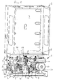
- the assembly 1 shown in the figures is arranged in the installed position in a chassis 2, which accommodates all components of the compact heating system and is attached to its rear wall 3 typically hanging on a wall or can be fixed floor-mounted or ceiling-mounted in providing a corresponding frame.
- the assembly 1 is arranged in the lower part of the chassis 2 and has four downgoing outgoing lines 4, 5, 6 and 7, which lie in a row parallel to the rear wall of the chassis 2 and to which the house-side water-carrying lines are connected.
- the upper part of the assembly 1 is, as usual in these devices, for receiving a burner and a primary heat exchanger arranged above it, these components are in Fig. 1 away.
- the assembly 1 has a right side in installation position upwards to the primary heat exchanger outgoing line 8, and a left side arranged, coming from the top of the primary heat exchanger line 9.
- a gas line 10 is guided, which is arranged in front of the unit 1 and in a likewise arranged in front of the unit 1 valve unit 11, which controls the gas supply to the burner.
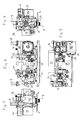
- the assembly 1 has a plate heat exchanger 12, which is arranged parallel to the rear wall 3 and is tabular. In the installation position, a first sub-assembly 13 shoots from the front on the plate heat exchanger 12 and a second sub-assembly 14 on the left side.
- the sub-assemblies 13 and 14 are essentially made of plastic injection molded bodies and arranged so that their mechanical connection substantially over the existing metal Plate heat exchanger 5 takes place.
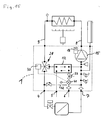
- the cable routing within the unit 1 and within the compact heating system results in detail Fig. 15 ,
- the flowing back from the return of the space heating water passes through the right in the installed position line connection in the line 7 and thus in the first sub-assembly 13, which includes, inter alia, a centrifugal pump 15 and an air separator 16.
- the line 7 opens into the suction chamber of the centrifugal pump 15, to which the air separator 16 connects at the top.
- the discharge nozzle of the pump 15 is connected to the leading to the primary heat exchanger line 8.
- the pump housing and the remaining lines of the first sub-assembly 13 are formed by an injection-molded component.
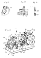
- the centrifugal pump 15 has, as usual in such units, a flanged, in the installed position accessible from the front electric motor 17, the terminal box 18 is disposed at the top of the motor housing.
- the line section 19 includes a flow diverting by 180 ° component 22, which connects the line section 19 with the right in the installed position next to it between pump 15 and line section 19 arranged right line section 20.
- the component 22 comprises a flow regulator, with which the flow rate is controlled, so that it is substantially independent of the line pressure.
- a pin-shaped actuating body 23 in the component 22 is arranged in alignment with the line section 20.
- the adjusting body has at its upper end a tool holder, here a square, with which it can be rotated about its longitudinal axis.
- the adjusting body 23 is mounted by means of a thread in the component 22, so that depending on the direction of rotation a flow-limiting provided with axis-parallel groove-like channels cone 24 more or less in an elastic receptacle 25 (see Fig. 13 ) can be inserted, which is incorporated at the upper end of the right line section 20.
- Such flow regulators are state of the art, which is why their function is not described in detail here.
- the component 22 is fastened by means of screws to the line sections 19 and 20 laterally projecting projections. If a flow rate regulator is not to be provided, the component 22 can be replaced by a 180 ° pipe bend without the injection molding component of the first substructure unit 13 adjoining it having to be changed.
- the installation in the lower end of the line section 20 is connected via an arcuately guided in the sub-assembly 13 channel line section 42 with the lower right in the installed position of the plate heat exchanger 12.
- the overlying upper port of the plate heat exchanger 12 is connected via a likewise arcuate line section 43 with the suction chamber of the pump 15.
- These line sections 42 and 43 are arc-shaped, so that they can be formed by pivot cores from the back of the sub-assembly 13, while allowing a certain lateral offset.
- the line section 42 has an opening at the bottom, which lines lead this line section 42 with a vertically downwardly leading channel 44, which formed widened down and forms a receptacle 45 for a valve 46, the valve body 47 via a from the outside between the Connection piece for the cold service water and the connection piece for the return of the heating water is arranged and accessible.
- This valve 46 has a sealing body 48 near the upper end of the valve body 47, which closes or opens the channel 44 depending on the position of the valve and then over the space formed by the receptacle 45 with a subsequent back within the sub-assembly 13 to the bypass line line and thus connects to the return side of the heating circuit.
- the sub-assembly 13 may be formed by correspondingly changing the take-up 45 and the channel 44 forming die core of the tool so that an opening between the channel 44 and the line section 42 is not formed. Then, the valve 46 is modified so that it forms only a connecting piece, which is connected depending on the position of the valve body 47 to the heating circuit or is closed off in contrast. This nozzle is then also used to fill or refill the heating circuit with water and is either fixed via a Disconnecteur, d. H.
- the right-hand conduit section 20 adjoins the lower right-hand connection of the plate heat exchanger 12 in the installed position so that the cold process water flows into the lower right-hand connection of the plate heat exchanger 12, flows through this to the lower left connection and there in a line part bent downwards through 90 ° opens, which forms at the end of the line 5 for emerging from the unit 1 warm hot water.
- This hot water is heated by heating water flowing countercurrently from the upper left port of the plate heat exchanger 12 to the upper right port.
- the upper right-hand connection is connected via a line section to the suction chamber of the pump 15 of the first sub-assembly 13.
- the emerging from the primary heat exchanger hot heat transfer medium passes through the line 9 via a line section 26, which is part of the second unit 14 and seen in the installation position extends down and behind in an arc (s. Fig. 2
- the receptacle 27 lies with its axis parallel to the plate heat exchanger 12 and at right angles askew to the impeller axis of the centrifugal pump 15.
- the recording is to the left in installation position from the left side a closure lid 29 accessible after removing the switch body can be pulled out of the receptacle side.
- the switching valve 28 is controlled by an electric servomotor 30, which is above the plate heat exchanger 12, however, arranged in front of this and the axis of rotation lies in a vertical plane in which the longitudinal axis of the receptacle 27 is seconded.
- the switching valve 28 with the associated servomotor 30 is not described in detail here, it is so far as an example EP 04 026 233 A1 referenced where such a valve is described in detail.
- the second sub-assembly 14, whose basic structure is also formed of a plastic injection molded part, thus includes the switching valve 28 with the corresponding line connections and is firmly connected to the left in the installed position line connections of the plate heat exchanger 12, thus also includes the line 5.
- the first sub-assembly 13 and the second sub-assembly 14 substantially connected to each other via the plate heat exchanger 12, but also connect other compounds, such as the bottom plate of the chassis 2 and a bypass line, but which are connected so that they in the longitudinal direction of the plate heat exchanger 12 (in installation position in horizontal Direction) are movably guided in order to avoid the introduction of thermal stresses due to different material expansions.
- a line section 31 to a bypass line 32, which connects the second sub-unit 14 with the first sub-unit 13 and laterally connected to the first sub-unit 13 in the region between plate heat exchanger 12 and the line sections 19 and 20 and thus forms a connection to the suction region of the pump 15.
- the line section 31 connects to a perpendicular thereto in the same plane extending line portion 33 which extends in addition to the plate heat exchanger 12 in alignment with it. This is angled in the installed position on the right side by 90 ° to the front and there goes into a line section 34 which is open toward the front and serves to receive a valve 35 in the form of an adjustable pressure relief valve.
- a line section 36 connects to the right, which extends parallel to the plate heat exchanger 12 in front of it.
- a back of this cantilevered support 37 comes to the bottom of the plate heat exchanger 12 to the plant.
- At this line section 36 in turn closes perpendicular to a fitting 38 receiving and thus open to the front line section on, which is designed here for example as a filling valve for filling the heating system with water.
- the right end of the line section 36 is provided with an O-ring 39 and guided only in the direction transverse to the longitudinal axis of the line section 36 in the corresponding aligned receiving the first sub-assembly 14 so that a movement in the axial direction to compensate for tolerances and thermal expansion is possible.
Landscapes
- Engineering & Computer Science (AREA)
- Physics & Mathematics (AREA)
- Thermal Sciences (AREA)
- Chemical & Material Sciences (AREA)
- Combustion & Propulsion (AREA)
- Mechanical Engineering (AREA)
- General Engineering & Computer Science (AREA)
- Steam Or Hot-Water Central Heating Systems (AREA)
Priority Applications (1)
| Application Number | Priority Date | Filing Date | Title |
|---|---|---|---|
| EP08003223.8A EP2093517B1 (fr) | 2008-02-22 | 2008-02-22 | Composant pour installation de chauffage compacte |
Applications Claiming Priority (1)
| Application Number | Priority Date | Filing Date | Title |
|---|---|---|---|
| EP08003223.8A EP2093517B1 (fr) | 2008-02-22 | 2008-02-22 | Composant pour installation de chauffage compacte |
Publications (2)
| Publication Number | Publication Date |
|---|---|
| EP2093517A1 true EP2093517A1 (fr) | 2009-08-26 |
| EP2093517B1 EP2093517B1 (fr) | 2014-01-15 |
Family
ID=39681308
Family Applications (1)
| Application Number | Title | Priority Date | Filing Date |
|---|---|---|---|
| EP08003223.8A Not-in-force EP2093517B1 (fr) | 2008-02-22 | 2008-02-22 | Composant pour installation de chauffage compacte |
Country Status (1)
| Country | Link |
|---|---|
| EP (1) | EP2093517B1 (fr) |
Cited By (5)
| Publication number | Priority date | Publication date | Assignee | Title |
|---|---|---|---|---|
| US20110308767A1 (en) * | 2010-06-19 | 2011-12-22 | Grundfos Management A/S | Housing unit for a heating system |
| EP2413044A1 (fr) * | 2010-07-30 | 2012-02-01 | Grundfos Management A/S | Unité de chauffage d'eau potable |
| ITMI20102164A1 (it) * | 2010-11-23 | 2012-05-24 | Riello Spa | Selettore di temperatura di uno scaldabagno per la produzione di acqua calda |
| EP3012553A1 (fr) * | 2014-10-21 | 2016-04-27 | Grundfos Holding A/S | Composant pour une installation de chauffage |
| EP2664858A3 (fr) * | 2012-05-19 | 2016-09-07 | Vaillant GmbH | Chauffe-eau à gaz pouvant être fixé à l'aide d'un adaptateur pour réaliser une fonction de chauffage central |
Families Citing this family (1)
| Publication number | Priority date | Publication date | Assignee | Title |
|---|---|---|---|---|
| DE202015004260U1 (de) * | 2015-06-16 | 2016-09-19 | Gebr. Kemper Gmbh + Co. Kg Metallwerke | Modul zur Wassererwärmung |
Citations (4)
| Publication number | Priority date | Publication date | Assignee | Title |
|---|---|---|---|---|
| EP0953808A2 (fr) | 1998-05-02 | 1999-11-03 | WILO GmbH | Unité hydraulique avec capteur de pression pour une installation combinée d'eau de chauffage et d'eau chaude sanitaire |
| EP1582824A2 (fr) | 2004-02-24 | 2005-10-05 | GV STAMPERIE S.p.A. | Dispositif de gestion de flux dans une chaudière mixte et chaudière mixte |
| EP1884720A1 (fr) * | 2006-07-28 | 2008-02-06 | Grundfos Management A/S | Ensemble pour installation de chauffage compact |
| EP1528330B1 (fr) | 2003-11-03 | 2008-06-04 | Grundfos A/S | Ensemble pour installation de chauffage compact |
-
2008
- 2008-02-22 EP EP08003223.8A patent/EP2093517B1/fr not_active Not-in-force
Patent Citations (4)
| Publication number | Priority date | Publication date | Assignee | Title |
|---|---|---|---|---|
| EP0953808A2 (fr) | 1998-05-02 | 1999-11-03 | WILO GmbH | Unité hydraulique avec capteur de pression pour une installation combinée d'eau de chauffage et d'eau chaude sanitaire |
| EP1528330B1 (fr) | 2003-11-03 | 2008-06-04 | Grundfos A/S | Ensemble pour installation de chauffage compact |
| EP1582824A2 (fr) | 2004-02-24 | 2005-10-05 | GV STAMPERIE S.p.A. | Dispositif de gestion de flux dans une chaudière mixte et chaudière mixte |
| EP1884720A1 (fr) * | 2006-07-28 | 2008-02-06 | Grundfos Management A/S | Ensemble pour installation de chauffage compact |
Cited By (11)
| Publication number | Priority date | Publication date | Assignee | Title |
|---|---|---|---|---|
| US20110308767A1 (en) * | 2010-06-19 | 2011-12-22 | Grundfos Management A/S | Housing unit for a heating system |
| US9612036B2 (en) * | 2010-06-19 | 2017-04-04 | Grundfos Management A/S | Housing unit for a heating system |
| EP2413044A1 (fr) * | 2010-07-30 | 2012-02-01 | Grundfos Management A/S | Unité de chauffage d'eau potable |
| CN102345927A (zh) * | 2010-07-30 | 2012-02-08 | 格伦德福斯管理联合股份公司 | 非饮用水加热单元 |
| US9366447B2 (en) | 2010-07-30 | 2016-06-14 | Grundfos Management A/S | Service water heating unit |
| ITMI20102164A1 (it) * | 2010-11-23 | 2012-05-24 | Riello Spa | Selettore di temperatura di uno scaldabagno per la produzione di acqua calda |
| WO2012070004A1 (fr) * | 2010-11-23 | 2012-05-31 | Riello S.P.A. | Sélecteur de température de chauffe-eau |
| EP2664858A3 (fr) * | 2012-05-19 | 2016-09-07 | Vaillant GmbH | Chauffe-eau à gaz pouvant être fixé à l'aide d'un adaptateur pour réaliser une fonction de chauffage central |
| EP3012553A1 (fr) * | 2014-10-21 | 2016-04-27 | Grundfos Holding A/S | Composant pour une installation de chauffage |
| CN105526615A (zh) * | 2014-10-21 | 2016-04-27 | 格兰富控股联合股份公司 | 用于供热设备的结构单元 |
| CN105526615B (zh) * | 2014-10-21 | 2019-08-02 | 格兰富控股联合股份公司 | 用于供热设备的结构单元 |
Also Published As
| Publication number | Publication date |
|---|---|
| EP2093517B1 (fr) | 2014-01-15 |
Similar Documents
| Publication | Publication Date | Title |
|---|---|---|
| EP2229550B1 (fr) | Soupape de recyclage des gaz d'échappement pour un véhicule automobile | |
| EP2093517B1 (fr) | Composant pour installation de chauffage compacte | |
| EP2397777A1 (fr) | Unité de boîtier pour une installation de chauffage | |
| EP1528330B1 (fr) | Ensemble pour installation de chauffage compact | |
| EP2213948A2 (fr) | Répartiteur de circuit de la cathode chaude | |
| DE10007873C1 (de) | Baueinheit für eine Kompaktheizungsanlage | |
| EP1528329B1 (fr) | Ensemble pour installation de chauffage compact | |
| EP2093515B1 (fr) | Composant partiel pour une installation de chauffage compacte | |
| EP1884720B1 (fr) | Ensemble pour installation de chauffage compact | |
| EP2196584A1 (fr) | Distributeur pour une installation de conduite d'eau | |
| DE19751515C2 (de) | Baueinheit für eine Kompaktheizungsanlage | |
| DE19912284B4 (de) | Kompaktheizungsanlage | |
| EP3012553B1 (fr) | Composant pour une installation de chauffage | |
| EP0358843B1 (fr) | Pompes pour une installation de chauffage à eau chaude | |
| WO2000055548A1 (fr) | Radiateur | |
| EP1884723B1 (fr) | Module | |
| EP1672286B1 (fr) | Distributeur pour un circuit de liquide d'une installation de chauffage | |
| EP1936314B1 (fr) | Réservoir d'eau chaude stratifié | |
| EP2093516B1 (fr) | Composant pour installation de chauffage compacte | |
| EP1136765B1 (fr) | Dispositif de raccordement pour un radiateur | |
| WO2019219377A1 (fr) | Dispositif pour relier au moins deux éléments de tuyau flexible ou de conduite à un logement | |
| WO2013087842A1 (fr) | Raccord rapide | |
| EP1760407A1 (fr) | Distributeur pour système de chauffage et de refroidissement | |
| EP2629019B1 (fr) | Unité de boîtier pour un appareil de chauffage | |
| EP1217310B1 (fr) | Unité compacte |
Legal Events
| Date | Code | Title | Description |
|---|---|---|---|
| PUAI | Public reference made under article 153(3) epc to a published international application that has entered the european phase |
Free format text: ORIGINAL CODE: 0009012 |
|
| AK | Designated contracting states |
Kind code of ref document: A1 Designated state(s): AT BE BG CH CY CZ DE DK EE ES FI FR GB GR HR HU IE IS IT LI LT LU LV MC MT NL NO PL PT RO SE SI SK TR |
|
| AX | Request for extension of the european patent |
Extension state: AL BA MK RS |
|
| 17P | Request for examination filed |
Effective date: 20100107 |
|
| 17Q | First examination report despatched |
Effective date: 20100312 |
|
| AKX | Designation fees paid |
Designated state(s): AT BE BG CH CY CZ DE DK EE ES FI FR GB GR HR HU IE IS IT LI LT LU LV MC MT NL NO PL PT RO SE SI SK TR |
|
| GRAP | Despatch of communication of intention to grant a patent |
Free format text: ORIGINAL CODE: EPIDOSNIGR1 |
|
| RIN1 | Information on inventor provided before grant (corrected) |
Inventor name: DOESSING, BENT Inventor name: JENSEN, OLAV Inventor name: GREVE, ROBERT |
|
| INTG | Intention to grant announced |
Effective date: 20130812 |
|
| GRAS | Grant fee paid |
Free format text: ORIGINAL CODE: EPIDOSNIGR3 |
|
| GRAA | (expected) grant |
Free format text: ORIGINAL CODE: 0009210 |
|
| AK | Designated contracting states |
Kind code of ref document: B1 Designated state(s): AT BE BG CH CY CZ DE DK EE ES FI FR GB GR HR HU IE IS IT LI LT LU LV MC MT NL NO PL PT RO SE SI SK TR |
|
| REG | Reference to a national code |
Ref country code: GB Ref legal event code: FG4D Free format text: NOT ENGLISH Ref country code: CH Ref legal event code: EP |
|
| REG | Reference to a national code |
Ref country code: AT Ref legal event code: REF Ref document number: 650014 Country of ref document: AT Kind code of ref document: T Effective date: 20140215 |
|
| REG | Reference to a national code |
Ref country code: DE Ref legal event code: R096 Ref document number: 502008011214 Country of ref document: DE Effective date: 20140220 |
|
| REG | Reference to a national code |
Ref country code: IE Ref legal event code: FG4D Free format text: LANGUAGE OF EP DOCUMENT: GERMAN |
|
| REG | Reference to a national code |
Ref country code: NL Ref legal event code: VDEP Effective date: 20140115 |
|
| REG | Reference to a national code |
Ref country code: LT Ref legal event code: MG4D |
|
| PG25 | Lapsed in a contracting state [announced via postgrant information from national office to epo] |
Ref country code: IS Free format text: LAPSE BECAUSE OF FAILURE TO SUBMIT A TRANSLATION OF THE DESCRIPTION OR TO PAY THE FEE WITHIN THE PRESCRIBED TIME-LIMIT Effective date: 20140515 Ref country code: LT Free format text: LAPSE BECAUSE OF FAILURE TO SUBMIT A TRANSLATION OF THE DESCRIPTION OR TO PAY THE FEE WITHIN THE PRESCRIBED TIME-LIMIT Effective date: 20140115 Ref country code: NO Free format text: LAPSE BECAUSE OF FAILURE TO SUBMIT A TRANSLATION OF THE DESCRIPTION OR TO PAY THE FEE WITHIN THE PRESCRIBED TIME-LIMIT Effective date: 20140415 |
|
| PG25 | Lapsed in a contracting state [announced via postgrant information from national office to epo] |
Ref country code: FI Free format text: LAPSE BECAUSE OF FAILURE TO SUBMIT A TRANSLATION OF THE DESCRIPTION OR TO PAY THE FEE WITHIN THE PRESCRIBED TIME-LIMIT Effective date: 20140115 Ref country code: ES Free format text: LAPSE BECAUSE OF FAILURE TO SUBMIT A TRANSLATION OF THE DESCRIPTION OR TO PAY THE FEE WITHIN THE PRESCRIBED TIME-LIMIT Effective date: 20140115 Ref country code: SE Free format text: LAPSE BECAUSE OF FAILURE TO SUBMIT A TRANSLATION OF THE DESCRIPTION OR TO PAY THE FEE WITHIN THE PRESCRIBED TIME-LIMIT Effective date: 20140115 Ref country code: PT Free format text: LAPSE BECAUSE OF FAILURE TO SUBMIT A TRANSLATION OF THE DESCRIPTION OR TO PAY THE FEE WITHIN THE PRESCRIBED TIME-LIMIT Effective date: 20140515 Ref country code: NL Free format text: LAPSE BECAUSE OF FAILURE TO SUBMIT A TRANSLATION OF THE DESCRIPTION OR TO PAY THE FEE WITHIN THE PRESCRIBED TIME-LIMIT Effective date: 20140115 Ref country code: CY Free format text: LAPSE BECAUSE OF FAILURE TO SUBMIT A TRANSLATION OF THE DESCRIPTION OR TO PAY THE FEE WITHIN THE PRESCRIBED TIME-LIMIT Effective date: 20140115 |
|
| BERE | Be: lapsed |
Owner name: GRUNDFOS MANAGEMENT A/S Effective date: 20140228 |
|
| PG25 | Lapsed in a contracting state [announced via postgrant information from national office to epo] |
Ref country code: HR Free format text: LAPSE BECAUSE OF FAILURE TO SUBMIT A TRANSLATION OF THE DESCRIPTION OR TO PAY THE FEE WITHIN THE PRESCRIBED TIME-LIMIT Effective date: 20140115 Ref country code: LV Free format text: LAPSE BECAUSE OF FAILURE TO SUBMIT A TRANSLATION OF THE DESCRIPTION OR TO PAY THE FEE WITHIN THE PRESCRIBED TIME-LIMIT Effective date: 20140115 |
|
| REG | Reference to a national code |
Ref country code: CH Ref legal event code: PL |
|
| REG | Reference to a national code |
Ref country code: DE Ref legal event code: R097 Ref document number: 502008011214 Country of ref document: DE |
|
| PG25 | Lapsed in a contracting state [announced via postgrant information from national office to epo] |
Ref country code: EE Free format text: LAPSE BECAUSE OF FAILURE TO SUBMIT A TRANSLATION OF THE DESCRIPTION OR TO PAY THE FEE WITHIN THE PRESCRIBED TIME-LIMIT Effective date: 20140115 Ref country code: DK Free format text: LAPSE BECAUSE OF FAILURE TO SUBMIT A TRANSLATION OF THE DESCRIPTION OR TO PAY THE FEE WITHIN THE PRESCRIBED TIME-LIMIT Effective date: 20140115 Ref country code: RO Free format text: LAPSE BECAUSE OF FAILURE TO SUBMIT A TRANSLATION OF THE DESCRIPTION OR TO PAY THE FEE WITHIN THE PRESCRIBED TIME-LIMIT Effective date: 20140115 Ref country code: CH Free format text: LAPSE BECAUSE OF NON-PAYMENT OF DUE FEES Effective date: 20140228 Ref country code: MC Free format text: LAPSE BECAUSE OF FAILURE TO SUBMIT A TRANSLATION OF THE DESCRIPTION OR TO PAY THE FEE WITHIN THE PRESCRIBED TIME-LIMIT Effective date: 20140115 Ref country code: LI Free format text: LAPSE BECAUSE OF NON-PAYMENT OF DUE FEES Effective date: 20140228 Ref country code: CZ Free format text: LAPSE BECAUSE OF FAILURE TO SUBMIT A TRANSLATION OF THE DESCRIPTION OR TO PAY THE FEE WITHIN THE PRESCRIBED TIME-LIMIT Effective date: 20140115 |
|
| PLBE | No opposition filed within time limit |
Free format text: ORIGINAL CODE: 0009261 |
|
| STAA | Information on the status of an ep patent application or granted ep patent |
Free format text: STATUS: NO OPPOSITION FILED WITHIN TIME LIMIT |
|
| PG25 | Lapsed in a contracting state [announced via postgrant information from national office to epo] |
Ref country code: PL Free format text: LAPSE BECAUSE OF FAILURE TO SUBMIT A TRANSLATION OF THE DESCRIPTION OR TO PAY THE FEE WITHIN THE PRESCRIBED TIME-LIMIT Effective date: 20140115 Ref country code: SK Free format text: LAPSE BECAUSE OF FAILURE TO SUBMIT A TRANSLATION OF THE DESCRIPTION OR TO PAY THE FEE WITHIN THE PRESCRIBED TIME-LIMIT Effective date: 20140115 |
|
| REG | Reference to a national code |
Ref country code: IE Ref legal event code: MM4A |
|
| 26N | No opposition filed |
Effective date: 20141016 |
|
| PG25 | Lapsed in a contracting state [announced via postgrant information from national office to epo] |
Ref country code: IE Free format text: LAPSE BECAUSE OF NON-PAYMENT OF DUE FEES Effective date: 20140222 Ref country code: BE Free format text: LAPSE BECAUSE OF NON-PAYMENT OF DUE FEES Effective date: 20140228 |
|
| REG | Reference to a national code |
Ref country code: DE Ref legal event code: R097 Ref document number: 502008011214 Country of ref document: DE Effective date: 20141016 |
|
| REG | Reference to a national code |
Ref country code: AT Ref legal event code: MM01 Ref document number: 650014 Country of ref document: AT Kind code of ref document: T Effective date: 20140222 |
|
| PG25 | Lapsed in a contracting state [announced via postgrant information from national office to epo] |
Ref country code: AT Free format text: LAPSE BECAUSE OF NON-PAYMENT OF DUE FEES Effective date: 20140222 Ref country code: SI Free format text: LAPSE BECAUSE OF FAILURE TO SUBMIT A TRANSLATION OF THE DESCRIPTION OR TO PAY THE FEE WITHIN THE PRESCRIBED TIME-LIMIT Effective date: 20140115 |
|
| REG | Reference to a national code |
Ref country code: FR Ref legal event code: PLFP Year of fee payment: 9 |
|
| PG25 | Lapsed in a contracting state [announced via postgrant information from national office to epo] |
Ref country code: MT Free format text: LAPSE BECAUSE OF FAILURE TO SUBMIT A TRANSLATION OF THE DESCRIPTION OR TO PAY THE FEE WITHIN THE PRESCRIBED TIME-LIMIT Effective date: 20140115 |
|
| PG25 | Lapsed in a contracting state [announced via postgrant information from national office to epo] |
Ref country code: BG Free format text: LAPSE BECAUSE OF FAILURE TO SUBMIT A TRANSLATION OF THE DESCRIPTION OR TO PAY THE FEE WITHIN THE PRESCRIBED TIME-LIMIT Effective date: 20140115 |
|
| PG25 | Lapsed in a contracting state [announced via postgrant information from national office to epo] |
Ref country code: GR Free format text: LAPSE BECAUSE OF FAILURE TO SUBMIT A TRANSLATION OF THE DESCRIPTION OR TO PAY THE FEE WITHIN THE PRESCRIBED TIME-LIMIT Effective date: 20140416 |
|
| PG25 | Lapsed in a contracting state [announced via postgrant information from national office to epo] |
Ref country code: LU Free format text: LAPSE BECAUSE OF NON-PAYMENT OF DUE FEES Effective date: 20140222 Ref country code: TR Free format text: LAPSE BECAUSE OF FAILURE TO SUBMIT A TRANSLATION OF THE DESCRIPTION OR TO PAY THE FEE WITHIN THE PRESCRIBED TIME-LIMIT Effective date: 20140115 Ref country code: HU Free format text: LAPSE BECAUSE OF FAILURE TO SUBMIT A TRANSLATION OF THE DESCRIPTION OR TO PAY THE FEE WITHIN THE PRESCRIBED TIME-LIMIT; INVALID AB INITIO Effective date: 20080222 |
|
| REG | Reference to a national code |
Ref country code: FR Ref legal event code: PLFP Year of fee payment: 10 |
|
| REG | Reference to a national code |
Ref country code: FR Ref legal event code: PLFP Year of fee payment: 11 |
|
| PGFP | Annual fee paid to national office [announced via postgrant information from national office to epo] |
Ref country code: GB Payment date: 20220221 Year of fee payment: 15 Ref country code: DE Payment date: 20220221 Year of fee payment: 15 |
|
| PGFP | Annual fee paid to national office [announced via postgrant information from national office to epo] |
Ref country code: IT Payment date: 20220228 Year of fee payment: 15 Ref country code: FR Payment date: 20220221 Year of fee payment: 15 |
|
| REG | Reference to a national code |
Ref country code: DE Ref legal event code: R082 Ref document number: 502008011214 Country of ref document: DE |
|
| REG | Reference to a national code |
Ref country code: DE Ref legal event code: R119 Ref document number: 502008011214 Country of ref document: DE |
|
| GBPC | Gb: european patent ceased through non-payment of renewal fee |
Effective date: 20230222 |
|
| PG25 | Lapsed in a contracting state [announced via postgrant information from national office to epo] |
Ref country code: GB Free format text: LAPSE BECAUSE OF NON-PAYMENT OF DUE FEES Effective date: 20230222 |
|
| PG25 | Lapsed in a contracting state [announced via postgrant information from national office to epo] |
Ref country code: IT Free format text: LAPSE BECAUSE OF NON-PAYMENT OF DUE FEES Effective date: 20230222 Ref country code: GB Free format text: LAPSE BECAUSE OF NON-PAYMENT OF DUE FEES Effective date: 20230222 Ref country code: FR Free format text: LAPSE BECAUSE OF NON-PAYMENT OF DUE FEES Effective date: 20230228 Ref country code: DE Free format text: LAPSE BECAUSE OF NON-PAYMENT OF DUE FEES Effective date: 20230901 |