EP2093531B1 - Structure de support à température constante - Google Patents
Structure de support à température constante Download PDFInfo
- Publication number
- EP2093531B1 EP2093531B1 EP09000929A EP09000929A EP2093531B1 EP 2093531 B1 EP2093531 B1 EP 2093531B1 EP 09000929 A EP09000929 A EP 09000929A EP 09000929 A EP09000929 A EP 09000929A EP 2093531 B1 EP2093531 B1 EP 2093531B1
- Authority
- EP
- European Patent Office
- Prior art keywords
- support structure
- structure according
- support
- spacer
- support beam
- Prior art date
- Legal status (The legal status is an assumption and is not a legal conclusion. Google has not performed a legal analysis and makes no representation as to the accuracy of the status listed.)
- Not-in-force
Links
- 239000002184 metal Substances 0.000 claims abstract description 27
- 229910052751 metal Inorganic materials 0.000 claims abstract description 27
- 239000000919 ceramic Substances 0.000 claims abstract description 16
- 125000006850 spacer group Chemical group 0.000 claims description 26
- 239000012774 insulation material Substances 0.000 claims description 5
- 238000000034 method Methods 0.000 claims description 4
- 239000000463 material Substances 0.000 description 11
- 239000011810 insulating material Substances 0.000 description 6
- 238000000137 annealing Methods 0.000 description 4
- 238000009413 insulation Methods 0.000 description 3
- 229910000640 Fe alloy Inorganic materials 0.000 description 2
- 230000001133 acceleration Effects 0.000 description 2
- 229910010293 ceramic material Inorganic materials 0.000 description 2
- BIJOYKCOMBZXAE-UHFFFAOYSA-N chromium iron nickel Chemical compound [Cr].[Fe].[Ni] BIJOYKCOMBZXAE-UHFFFAOYSA-N 0.000 description 2
- 230000001419 dependent effect Effects 0.000 description 2
- 150000002739 metals Chemical class 0.000 description 2
- PNEYBMLMFCGWSK-UHFFFAOYSA-N aluminium oxide Inorganic materials [O-2].[O-2].[O-2].[Al+3].[Al+3] PNEYBMLMFCGWSK-UHFFFAOYSA-N 0.000 description 1
- 238000005452 bending Methods 0.000 description 1
- 239000000969 carrier Substances 0.000 description 1
- 230000000295 complement effect Effects 0.000 description 1
- 229910052878 cordierite Inorganic materials 0.000 description 1
- 230000001934 delay Effects 0.000 description 1
- 238000011161 development Methods 0.000 description 1
- 230000018109 developmental process Effects 0.000 description 1
- JSKIRARMQDRGJZ-UHFFFAOYSA-N dimagnesium dioxido-bis[(1-oxido-3-oxo-2,4,6,8,9-pentaoxa-1,3-disila-5,7-dialuminabicyclo[3.3.1]nonan-7-yl)oxy]silane Chemical compound [Mg++].[Mg++].[O-][Si]([O-])(O[Al]1O[Al]2O[Si](=O)O[Si]([O-])(O1)O2)O[Al]1O[Al]2O[Si](=O)O[Si]([O-])(O1)O2 JSKIRARMQDRGJZ-UHFFFAOYSA-N 0.000 description 1
- KZHJGOXRZJKJNY-UHFFFAOYSA-N dioxosilane;oxo(oxoalumanyloxy)alumane Chemical compound O=[Si]=O.O=[Si]=O.O=[Al]O[Al]=O.O=[Al]O[Al]=O.O=[Al]O[Al]=O KZHJGOXRZJKJNY-UHFFFAOYSA-N 0.000 description 1
- 230000000694 effects Effects 0.000 description 1
- 238000010304 firing Methods 0.000 description 1
- 230000005484 gravity Effects 0.000 description 1
- 238000009434 installation Methods 0.000 description 1
- 238000012423 maintenance Methods 0.000 description 1
- 238000002844 melting Methods 0.000 description 1
- 230000008018 melting Effects 0.000 description 1
- 239000007769 metal material Substances 0.000 description 1
- 239000011490 mineral wool Substances 0.000 description 1
- 229910003465 moissanite Inorganic materials 0.000 description 1
- 229910052863 mullite Inorganic materials 0.000 description 1
- 239000011214 refractory ceramic Substances 0.000 description 1
- 229910010271 silicon carbide Inorganic materials 0.000 description 1
Images
Classifications
-
- F—MECHANICAL ENGINEERING; LIGHTING; HEATING; WEAPONS; BLASTING
- F27—FURNACES; KILNS; OVENS; RETORTS
- F27D—DETAILS OR ACCESSORIES OF FURNACES, KILNS, OVENS OR RETORTS, IN SO FAR AS THEY ARE OF KINDS OCCURRING IN MORE THAN ONE KIND OF FURNACE
- F27D5/00—Supports, screens or the like for the charge within the furnace
- F27D5/0006—Composite supporting structures
-
- F—MECHANICAL ENGINEERING; LIGHTING; HEATING; WEAPONS; BLASTING
- F27—FURNACES; KILNS; OVENS; RETORTS
- F27D—DETAILS OR ACCESSORIES OF FURNACES, KILNS, OVENS OR RETORTS, IN SO FAR AS THEY ARE OF KINDS OCCURRING IN MORE THAN ONE KIND OF FURNACE
- F27D3/00—Charging; Discharging; Manipulation of charge
- F27D3/12—Travelling or movable supports or containers for the charge
- F27D3/123—Furnace cars
Definitions
- the invention relates to a temperature-resistant support structure for industrial furnace applications.
- the invention relates to a support structure according to claim 1.
- German Offenlegungsschrift discloses DE 10 2005 005 607 a kiln furniture comprising at least two kiln furniture parts of different refractory ceramic materials.
- the two Brennosffenmaschine are positively connected to a kiln furniture and the materials of the two parts are chosen so that they complement each other in terms of their properties in the high and low temperature range.
- the invention provides a temperature-resistant support structure for use in furnaces, wherein the support structure has a mounting plate on which a spacer is arranged, which carries a support beam made of ceramic.
- a metal clamping device presses the support beam onto the spacer.
- the clamping means is designed as a metal band which engages over the support beam.
- At least one end of the metal strip is fixedly connected to a threaded bolt which projects through an opening of the mounting plate and onto which a nut is screwed, wherein between the nut and the mounting plate is a coil spring which cooperates with the screwed Nut and the mounting plate exerts a tensile force on the metal strip as an abutment.
- both ends of the metal strip are firmly connected to a respective threaded bolt, so that an elastic tensile force can be exerted on both ends of the metal strip.
- the metal band is fixed to the one end Attached mounting plate, while only the other end is firmly connected to a threaded bolt.
- the spacer is made of temperature-resistant metal and is designed for example as a hollow column.
- a support surface is provided for the support beam, which is preferably adapted to the shape of the support beam. From the bearing surface projects in one embodiment of the invention, a locking pin which projects into an opening in the supporting beam.
- the support structure comprises insulating material surrounding the spacer. Additionally, there may be additional insulation material inside the hollow spacer.
- the insulating material may for example be formed so thick that protrudes from the insulating material only an end portion of the spacer, which carries the support beam.
- two or more spacers are provided with straps between which the support beam extends.
- the support structure may be arranged on a mobile kiln car or fixedly installed in a furnace.
- the mounting plate can be formed by a furnace wall.
- the advantage of the invention is that ceramic materials are combined with metallic materials for a support structure so that their respective advantages can be utilized when used in an oven.
- the elastic tensile force on a metal strip, which overlaps a support beam thereby enables the compensation of different thermal expansions of the two materials ceramic and metal, so that a stable support structure is created, which meets the requirements for different furnace applications.
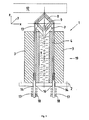
- FIG. 1 an embodiment of a support structure according to the invention is shown schematically.
- the support structure as a whole is designated by the reference numeral 1.
- the support structure is preferably installed for transport and storage of annealing material in an oven from the lower cold outer wall and attached to a mounting plate 2 made of metal.
- the mounting plate can be located inside or outside the furnace housing. Furthermore, the mounting plate can also be formed by the furnace wall itself, so that the support structure is attached directly to the metallic outer wall of the furnace.
- the support structure according to the invention is thus versatile. For example, it may be permanently installed in a furnace, the two described types of fastening to the furnace wall or to a mounting plate in the cold part of a furnace interior in question. If the support structure is designed to be movable, it can for example be attached to a carriage which can be moved through the furnace. The carriage can be moved, for example, in a gutter, which is located at the bottom of the furnace. Regardless of the use of the support structure in a furnace, this is therefore preferably attached to a mounting plate, wherein the plate can be mounted in turn in many ways on the furnace or on movable components.
- the mounting plate 2 is also usually separated from the hot part of the furnace by an insulating layer 3 of insulating material. If the support structure is attached to the outer shell of the furnace, the insulation is, for example, the furnace insulation.
- the layer thickness of the insulating layer 3 is usually between 150 and 450 mm.
- a metallic spacer 4 is fixed, which has approximately the same height as the insulating layer.
- the spacer 4 may be welded to the mounting plate 2, for example.
- the type of attachment is not essential to the invention, however, as long as the connection between the spacer 4 and the mounting plate 2 is temperature-resistant.
- the spacer 4 is formed for example as a hollow profile, the interior of which is filled with further insulating material 6.
- insulating material 6 for example, a mineral wool can be used, which has a high melting point.
- a V-shaped support 7 is arranged, which provides a large support surface for a ceramic support beam 8.
- the support beam 8 is formed for example as a square hollow section and may consist of known materials such as cordierite, mullite, alumina or SiC, which have been proven for furnace applications.
- the V-shaped bearing surface of the support 7 provides for a distribution of the contact pressure and thus for reducing the risk of breakage of the ceramic support beam 8 as compared to a support beam directly, the helpless without the V-shaped support 7, on the spacer 4 would rest.
- the V-shaped support 7 fixes the position of the support beam 8 in a first horizontal direction, which in FIG. 1 is denoted by x.
- the V-shaped bearing surface 7 has the shape of a rectangular angle profile.
- the edition 7 can take other forms. It is only essential that the support 7 is adapted to the outer shape of the support beam 8 in order to reduce the contact pressure.
- a locking pin 9 is preferably arranged, which protrudes from the supporting beam 8 facing support surface of the support 7 and projects into a corresponding opening 11 in the hollow support beam 8.
- the locking pin 9 fixes the position of the support beam 8 in a second horizontal direction, in FIG. 1 is denoted by y.
- the annealed material 12 comes to lie on the supporting beam 8.
- the support beam 8 is additionally elastically held by a biased by tensile metal clamping band 13 by being pressed into the V-shaped support 7 and the locking pin 9.
- the support beam 8 is also fixed in a vertical direction, which in FIG. 1 is denoted by z.
- the two ends of the tension band 13 are fixedly connected to threaded bolts 14 which protrude through openings 16 in the mounting plate 2.
- nuts 18 are attached on the protruding under the mounting plate 2 free ends of the threaded bolt 14 nuts 18 are attached. These nuts serve as adjusting and fastening nuts.
- each coil springs 17 are mounted, which are compressed when tightening the nuts 18 against the underside of the mounting plate 2.
- the coil springs exert an elastic tensile force on the metal strip 13 in the tensioned state.
- the mounting plate 2 serves as an abutment for the coil springs 17th
- the coil springs 17 serve to compensate for the different thermal expansions of the two materials metal and ceramic, as well as to compensate for the changes in shape of the temperature-creeping metal of the clamping band 13 and the spacer 4. With the help of cold nuts 18 can be restored in maintenance intervals, the necessary bias.
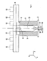
- FIG. 2 an embodiment of the support structure 1 according to the invention is shown in a viewing direction, in the FIG. 1 is indicated by the arrow 19.
- the picture in FIG. 2 It can be seen that the V-shaped support is formed so long that the support beam is stable on it.
- one end of the tension band 13 is fixed to the mounting plate 2, while only the other end of the tension band 13 is fixed to a threaded bolt 14, as shown in the FIGS. 1 and 2 is shown.
- the tensile force is adjusted only at one end to the clamping band 13.
- This arrangement is suitable, for example, for round support beams on which the tensioning band 13 slips without appreciable friction.
- metallic punches can be provided, for example, which press the ceramic support bar 8 from above onto the V-shaped support 7.
- These stamps have at their lower ends in each case also a V-shaped support, which corresponds to the outer shape of the support beam 8.
- the punches are also elastically sprung by a spring arrangement, so that the thermal expansion of the punches and the spacer can be compensated and a constant pressure is exerted on the support beam.
Landscapes
- Engineering & Computer Science (AREA)
- Mechanical Engineering (AREA)
- General Engineering & Computer Science (AREA)
- Furnace Charging Or Discharging (AREA)
- Springs (AREA)
- Connection Of Plates (AREA)
Claims (15)
- Structure de support résistante à la chaleur pour utilisation dans des fours, la structure de support comportant une plaque de fixation (2) sur laquelle est disposée une pièce d'écartement (4) qui supporte une barre de support (8) en céramique, caractérisée en ce qu'est prévu un moyen de serrage (13, 14, 17, 18) en métal qui presse la barre de support (8) contre la pièce d'écartement (4), le moyen de serrage (13, 14, 17, 18) comprenant une bande métallique (13) qui enserre la barre de support (8).
- Structure de support selon la revendication 1, caractérisée en ce qu'au moins une extrémité de la bande métallique (13) est solidaire d'un boulon fileté (14) qui fait saillie par un orifice (16) de la plaque de fixation (2) et sur lequel est vissé un écrou (18), un ressort à boudin (17) se trouvant entre l'écrou (18) et la plaque de fixation (2) de sorte que, étant donné la coopération entre le ressort à boudin (17) et l'écrou vissé (18) ainsi que la plaque de fixation en tant que butée (2), une force de traction est exercée sur la bande métallique (13).
- Structure de support selon la revendication 2, caractérisée en ce que les deux extrémités de la bande métallique (13) sont chacune solidaires d'un boulon fileté (14).
- Structure de support selon la revendication 2, caractérisée en ce que la bande métallique (13) est solidaire de la plaque de fixation (2) en une extrémité tandis que l'autre extrémité est solidaire d'un boulon fileté (14).
- Structure de support selon l'une des revendications 1 à 4, caractérisée en ce que la pièce d'écartement (4) se présente sous la forme d'une colonne creuse.
- Structure de support selon l'une des revendications 1 à 5, caractérisée en ce qu'est prévue, sur la pièce d'écartement (4), une surface d'appui (7) pour la barre de support (8).
- Structure de support selon la revendication 6, caractérisée en ce que la surface d'appui (7) est adaptée à la forme de la barre de support (8).
- Structure de support selon l'une des revendications 5 et 6, caractérisée en ce que fait saillie, hors de la surface d'appui (7), un boulon de blocage (9) qui fait saillie dans un orifice (11) ménagé dans la barre de support (8).
- Structure de support selon l'une des revendications 1 à 8, caractérisée en ce que sont prévues deux pièces d'écartement (4) avec des bandes de serrage (13) entre lesquelles s'étend la barre de support (8).
- Structure de support selon l'une des revendications 1 à 9, caractérisée en ce que la structure de support comprend un matériau isolant (3) qui entoure la pièce d'écartement (4).
- Structure de support selon l'une des revendications 5 à 10, caractérisée en ce qu'un matériau isolant (6) se trouve à l'intérieur de la pièce d'écartement creuse (4).
- Structure de support selon l'une des revendications 10 et 11, caractérisée en ce que seule une zone terminale de la pièce d'écartement (4) qui supporte la barre de support (8) fait saillie hors du matériau isolant (3, 6).
- Chariot de four mobile avec une structure de support résistante à la température selon les revendications 1 à 12, caractérisé en ce que la structure de support est agencée sur le chariot de four.
- Four avec une structure de support résistante à la température selon les revendications 1 à 12, caractérisé en ce que la structure de support est installée à demeure dans le four.
- Four selon la revendication 14, caractérisé en ce que la plaque de fixation (2) de la structure de support est formée par une paroi du four.
Priority Applications (1)
| Application Number | Priority Date | Filing Date | Title |
|---|---|---|---|
| PL09000929T PL2093531T3 (pl) | 2008-02-13 | 2009-01-23 | Odporna na temperaturę konstrukcja nośna |
Applications Claiming Priority (1)
| Application Number | Priority Date | Filing Date | Title |
|---|---|---|---|
| DE102008008990A DE102008008990B4 (de) | 2008-02-13 | 2008-02-13 | Temperaturbeständige Tragstruktur und deren Verwendung |
Publications (2)
| Publication Number | Publication Date |
|---|---|
| EP2093531A1 EP2093531A1 (fr) | 2009-08-26 |
| EP2093531B1 true EP2093531B1 (fr) | 2011-04-13 |
Family
ID=40602248
Family Applications (1)
| Application Number | Title | Priority Date | Filing Date |
|---|---|---|---|
| EP09000929A Not-in-force EP2093531B1 (fr) | 2008-02-13 | 2009-01-23 | Structure de support à température constante |
Country Status (5)
| Country | Link |
|---|---|
| EP (1) | EP2093531B1 (fr) |
| AT (1) | ATE505700T1 (fr) |
| DE (2) | DE102008008990B4 (fr) |
| ES (1) | ES2363191T3 (fr) |
| PL (1) | PL2093531T3 (fr) |
Family Cites Families (6)
| Publication number | Priority date | Publication date | Assignee | Title |
|---|---|---|---|---|
| DE8116662U1 (de) * | 1981-06-05 | 1981-10-01 | Peter, Hubertus, Dr., 6650 Homburg | Regalaufbau fuer brennwagen der keramischen industrie |
| DE4020284A1 (de) * | 1990-06-26 | 1992-01-02 | Norton Gmbh | Ofenwagen mit austauschbaren stuetzelementen |
| DE19931306C2 (de) * | 1999-07-07 | 2001-08-02 | Lipinski Tadeusz Von Rymon | Verfahren zur Herstellung von leichten keramischen Bauteilen sowie Bausatz zur Erstellung eines solchen leichten keramischen Bauteils |
| ATE519086T1 (de) * | 2003-06-27 | 2011-08-15 | Ceramic Technology Europ Ltd | Ofen, insbesondere für keramikprodukt |
| DE102005003500A1 (de) * | 2005-01-25 | 2006-07-27 | Saint-Gobain Industriekeramik Rödental GmbH | Brennguttragevorrichtung mit elastischer Stützenfixierung |
| DE102005005607A1 (de) * | 2005-02-07 | 2006-08-10 | Saint-Gobain Industriekeramik Rödental GmbH | Brennhilfsmittel für Brennwagenaufbauten und Feuerfestzustellungen und Verfahren dessen Herstellung |
-
2008
- 2008-02-13 DE DE102008008990A patent/DE102008008990B4/de not_active Expired - Fee Related
-
2009
- 2009-01-23 AT AT09000929T patent/ATE505700T1/de active
- 2009-01-23 PL PL09000929T patent/PL2093531T3/pl unknown
- 2009-01-23 DE DE502009000510T patent/DE502009000510D1/de active Active
- 2009-01-23 EP EP09000929A patent/EP2093531B1/fr not_active Not-in-force
- 2009-01-23 ES ES09000929T patent/ES2363191T3/es active Active
Also Published As
| Publication number | Publication date |
|---|---|
| DE102008008990A1 (de) | 2009-09-10 |
| ES2363191T3 (es) | 2011-07-26 |
| DE502009000510D1 (de) | 2011-05-26 |
| ATE505700T1 (de) | 2011-04-15 |
| DE102008008990B4 (de) | 2009-11-26 |
| PL2093531T3 (pl) | 2011-10-31 |
| EP2093531A1 (fr) | 2009-08-26 |
Similar Documents
| Publication | Publication Date | Title |
|---|---|---|
| EP0558540B1 (fr) | Ecran thermique en ceramique monte sur une structure portante | |
| EP1532281B1 (fr) | Plaque de refroidissement pour fours metalliques | |
| EP3409556B1 (fr) | Système de fixation, armoire de protection contre l'incendie et moyen de transport comportant une armoire de protection contre l'incendie | |
| DE3625056A1 (de) | Feuerfeste auskleidung, insbesondere fuer brennkammern von gasturbinenanlagen | |
| EP3113891B1 (fr) | Coulisseau porte-outil | |
| DE102010033816A1 (de) | Temperiertes Werkzeug | |
| EP2093531B1 (fr) | Structure de support à température constante | |
| DE102009029767B4 (de) | Fixierung eines Bauteils während einer Wärmebehandlung | |
| EP3728651B1 (fr) | Cuve métallurgique inclinable et procédé de fixation et de libération d'un récipient métallurgique inclinable | |
| EP0317494A2 (fr) | Porte de four à coke d'une construction à bouclier céramique | |
| EP3227567B1 (fr) | Dispositif de contraction d'un premier élément structural et d'un second élément structural | |
| DE102014102993A1 (de) | Werkzeugschieber | |
| EP2322889B1 (fr) | Dispositif de retenue pour une pierre d'ancrage céramique et four doté d'un tel dispositif de retenue | |
| EP1612483B1 (fr) | Elément de grille, grille de combustion associée et installation d'incinération de matière résiduelle | |
| EP1128131A1 (fr) | Bouclier thermique, chambre de combustion et turbine à gaz | |
| WO2000048769A1 (fr) | Colonne montante pour matieres metalliques en fusion | |
| EP3379900B1 (fr) | Table de cuisson | |
| EP0939270A1 (fr) | Dispositif avec un tube à jet | |
| DE2737960C2 (de) | Konverter mit einem abnehmbaren Boden | |
| EP3757497A1 (fr) | Chaussure de rayonnement | |
| EP4072894A1 (fr) | Résistance de freinage et véhicule équipé de cette dernière | |
| DE102012003471A1 (de) | Thermogeneratoreinrichtung für einen Gaskocher und Gaskocher | |
| AT407786B (de) | Befestigungsvorrichtung für verkleidungselemente einer heizeinrichtung | |
| DE102018129446B4 (de) | Balken für Balkenförderofen | |
| DE3903147C2 (fr) |
Legal Events
| Date | Code | Title | Description |
|---|---|---|---|
| PUAI | Public reference made under article 153(3) epc to a published international application that has entered the european phase |
Free format text: ORIGINAL CODE: 0009012 |
|
| AK | Designated contracting states |
Kind code of ref document: A1 Designated state(s): AT BE BG CH CY CZ DE DK EE ES FI FR GB GR HR HU IE IS IT LI LT LU LV MC MK MT NL NO PL PT RO SE SI SK TR |
|
| AX | Request for extension of the european patent |
Extension state: AL BA RS |
|
| 17P | Request for examination filed |
Effective date: 20100226 |
|
| 17Q | First examination report despatched |
Effective date: 20100401 |
|
| AKX | Designation fees paid |
Designated state(s): AT BE BG CH CY CZ DE DK EE ES FI FR GB GR HR HU IE IS IT LI LT LU LV MC MK MT NL NO PL PT RO SE SI SK TR |
|
| GRAP | Despatch of communication of intention to grant a patent |
Free format text: ORIGINAL CODE: EPIDOSNIGR1 |
|
| GRAC | Information related to communication of intention to grant a patent modified |
Free format text: ORIGINAL CODE: EPIDOSCIGR1 |
|
| GRAS | Grant fee paid |
Free format text: ORIGINAL CODE: EPIDOSNIGR3 |
|
| GRAA | (expected) grant |
Free format text: ORIGINAL CODE: 0009210 |
|
| AK | Designated contracting states |
Kind code of ref document: B1 Designated state(s): AT BE BG CH CY CZ DE DK EE ES FI FR GB GR HR HU IE IS IT LI LT LU LV MC MK MT NL NO PL PT RO SE SI SK TR |
|
| REG | Reference to a national code |
Ref country code: GB Ref legal event code: FG4D Free format text: NOT ENGLISH |
|
| REG | Reference to a national code |
Ref country code: CH Ref legal event code: EP |
|
| REG | Reference to a national code |
Ref country code: IE Ref legal event code: FG4D Free format text: LANGUAGE OF EP DOCUMENT: GERMAN |
|
| REF | Corresponds to: |
Ref document number: 502009000510 Country of ref document: DE Date of ref document: 20110526 Kind code of ref document: P |
|
| REG | Reference to a national code |
Ref country code: DE Ref legal event code: R096 Ref document number: 502009000510 Country of ref document: DE Effective date: 20110526 |
|
| REG | Reference to a national code |
Ref country code: SE Ref legal event code: TRGR |
|
| REG | Reference to a national code |
Ref country code: ES Ref legal event code: FG2A Ref document number: 2363191 Country of ref document: ES Kind code of ref document: T3 Effective date: 20110726 |
|
| REG | Reference to a national code |
Ref country code: NL Ref legal event code: VDEP Effective date: 20110413 |
|
| LTIE | Lt: invalidation of european patent or patent extension |
Effective date: 20110413 |
|
| PG25 | Lapsed in a contracting state [announced via postgrant information from national office to epo] |
Ref country code: HR Free format text: LAPSE BECAUSE OF FAILURE TO SUBMIT A TRANSLATION OF THE DESCRIPTION OR TO PAY THE FEE WITHIN THE PRESCRIBED TIME-LIMIT Effective date: 20110413 Ref country code: NO Free format text: LAPSE BECAUSE OF FAILURE TO SUBMIT A TRANSLATION OF THE DESCRIPTION OR TO PAY THE FEE WITHIN THE PRESCRIBED TIME-LIMIT Effective date: 20110713 Ref country code: LT Free format text: LAPSE BECAUSE OF FAILURE TO SUBMIT A TRANSLATION OF THE DESCRIPTION OR TO PAY THE FEE WITHIN THE PRESCRIBED TIME-LIMIT Effective date: 20110413 Ref country code: PT Free format text: LAPSE BECAUSE OF FAILURE TO SUBMIT A TRANSLATION OF THE DESCRIPTION OR TO PAY THE FEE WITHIN THE PRESCRIBED TIME-LIMIT Effective date: 20110816 |
|
| REG | Reference to a national code |
Ref country code: PL Ref legal event code: T3 |
|
| REG | Reference to a national code |
Ref country code: IE Ref legal event code: FD4D |
|
| PG25 | Lapsed in a contracting state [announced via postgrant information from national office to epo] |
Ref country code: SI Free format text: LAPSE BECAUSE OF FAILURE TO SUBMIT A TRANSLATION OF THE DESCRIPTION OR TO PAY THE FEE WITHIN THE PRESCRIBED TIME-LIMIT Effective date: 20110413 Ref country code: FI Free format text: LAPSE BECAUSE OF FAILURE TO SUBMIT A TRANSLATION OF THE DESCRIPTION OR TO PAY THE FEE WITHIN THE PRESCRIBED TIME-LIMIT Effective date: 20110413 Ref country code: LV Free format text: LAPSE BECAUSE OF FAILURE TO SUBMIT A TRANSLATION OF THE DESCRIPTION OR TO PAY THE FEE WITHIN THE PRESCRIBED TIME-LIMIT Effective date: 20110413 Ref country code: IS Free format text: LAPSE BECAUSE OF FAILURE TO SUBMIT A TRANSLATION OF THE DESCRIPTION OR TO PAY THE FEE WITHIN THE PRESCRIBED TIME-LIMIT Effective date: 20110813 Ref country code: GR Free format text: LAPSE BECAUSE OF FAILURE TO SUBMIT A TRANSLATION OF THE DESCRIPTION OR TO PAY THE FEE WITHIN THE PRESCRIBED TIME-LIMIT Effective date: 20110714 Ref country code: CY Free format text: LAPSE BECAUSE OF FAILURE TO SUBMIT A TRANSLATION OF THE DESCRIPTION OR TO PAY THE FEE WITHIN THE PRESCRIBED TIME-LIMIT Effective date: 20110413 |
|
| PG25 | Lapsed in a contracting state [announced via postgrant information from national office to epo] |
Ref country code: NL Free format text: LAPSE BECAUSE OF FAILURE TO SUBMIT A TRANSLATION OF THE DESCRIPTION OR TO PAY THE FEE WITHIN THE PRESCRIBED TIME-LIMIT Effective date: 20110413 |
|
| PG25 | Lapsed in a contracting state [announced via postgrant information from national office to epo] |
Ref country code: IE Free format text: LAPSE BECAUSE OF FAILURE TO SUBMIT A TRANSLATION OF THE DESCRIPTION OR TO PAY THE FEE WITHIN THE PRESCRIBED TIME-LIMIT Effective date: 20110413 Ref country code: EE Free format text: LAPSE BECAUSE OF FAILURE TO SUBMIT A TRANSLATION OF THE DESCRIPTION OR TO PAY THE FEE WITHIN THE PRESCRIBED TIME-LIMIT Effective date: 20110413 |
|
| PLBE | No opposition filed within time limit |
Free format text: ORIGINAL CODE: 0009261 |
|
| STAA | Information on the status of an ep patent application or granted ep patent |
Free format text: STATUS: NO OPPOSITION FILED WITHIN TIME LIMIT |
|
| PG25 | Lapsed in a contracting state [announced via postgrant information from national office to epo] |
Ref country code: DK Free format text: LAPSE BECAUSE OF FAILURE TO SUBMIT A TRANSLATION OF THE DESCRIPTION OR TO PAY THE FEE WITHIN THE PRESCRIBED TIME-LIMIT Effective date: 20110413 Ref country code: SK Free format text: LAPSE BECAUSE OF FAILURE TO SUBMIT A TRANSLATION OF THE DESCRIPTION OR TO PAY THE FEE WITHIN THE PRESCRIBED TIME-LIMIT Effective date: 20110413 Ref country code: RO Free format text: LAPSE BECAUSE OF FAILURE TO SUBMIT A TRANSLATION OF THE DESCRIPTION OR TO PAY THE FEE WITHIN THE PRESCRIBED TIME-LIMIT Effective date: 20110413 |
|
| 26N | No opposition filed |
Effective date: 20120116 |
|
| REG | Reference to a national code |
Ref country code: DE Ref legal event code: R097 Ref document number: 502009000510 Country of ref document: DE Effective date: 20120116 |
|
| BERE | Be: lapsed |
Owner name: SCHWARTZ, EVA Effective date: 20120131 |
|
| PG25 | Lapsed in a contracting state [announced via postgrant information from national office to epo] |
Ref country code: MC Free format text: LAPSE BECAUSE OF NON-PAYMENT OF DUE FEES Effective date: 20120131 |
|
| PG25 | Lapsed in a contracting state [announced via postgrant information from national office to epo] |
Ref country code: BE Free format text: LAPSE BECAUSE OF NON-PAYMENT OF DUE FEES Effective date: 20120131 |
|
| PG25 | Lapsed in a contracting state [announced via postgrant information from national office to epo] |
Ref country code: MK Free format text: LAPSE BECAUSE OF FAILURE TO SUBMIT A TRANSLATION OF THE DESCRIPTION OR TO PAY THE FEE WITHIN THE PRESCRIBED TIME-LIMIT Effective date: 20110413 |
|
| PG25 | Lapsed in a contracting state [announced via postgrant information from national office to epo] |
Ref country code: BG Free format text: LAPSE BECAUSE OF FAILURE TO SUBMIT A TRANSLATION OF THE DESCRIPTION OR TO PAY THE FEE WITHIN THE PRESCRIBED TIME-LIMIT Effective date: 20110713 |
|
| PG25 | Lapsed in a contracting state [announced via postgrant information from national office to epo] |
Ref country code: MT Free format text: LAPSE BECAUSE OF FAILURE TO SUBMIT A TRANSLATION OF THE DESCRIPTION OR TO PAY THE FEE WITHIN THE PRESCRIBED TIME-LIMIT Effective date: 20110413 |
|
| REG | Reference to a national code |
Ref country code: CH Ref legal event code: PL |
|
| PG25 | Lapsed in a contracting state [announced via postgrant information from national office to epo] |
Ref country code: LI Free format text: LAPSE BECAUSE OF NON-PAYMENT OF DUE FEES Effective date: 20130131 Ref country code: CH Free format text: LAPSE BECAUSE OF NON-PAYMENT OF DUE FEES Effective date: 20130131 |
|
| PG25 | Lapsed in a contracting state [announced via postgrant information from national office to epo] |
Ref country code: TR Free format text: LAPSE BECAUSE OF FAILURE TO SUBMIT A TRANSLATION OF THE DESCRIPTION OR TO PAY THE FEE WITHIN THE PRESCRIBED TIME-LIMIT Effective date: 20110413 |
|
| PG25 | Lapsed in a contracting state [announced via postgrant information from national office to epo] |
Ref country code: LU Free format text: LAPSE BECAUSE OF NON-PAYMENT OF DUE FEES Effective date: 20120123 |
|
| PG25 | Lapsed in a contracting state [announced via postgrant information from national office to epo] |
Ref country code: HU Free format text: LAPSE BECAUSE OF FAILURE TO SUBMIT A TRANSLATION OF THE DESCRIPTION OR TO PAY THE FEE WITHIN THE PRESCRIBED TIME-LIMIT Effective date: 20090123 |
|
| REG | Reference to a national code |
Ref country code: DE Ref legal event code: R082 Ref document number: 502009000510 Country of ref document: DE Representative=s name: JOSTARNDT PATENTANWALTS-AG, DE |
|
| REG | Reference to a national code |
Ref country code: DE Ref legal event code: R082 Ref document number: 502009000510 Country of ref document: DE Representative=s name: JOSTARNDT PATENTANWALTS-AG, DE Effective date: 20150227 Ref country code: DE Ref legal event code: R081 Ref document number: 502009000510 Country of ref document: DE Owner name: SCHWARTZ GMBH, DE Free format text: FORMER OWNER: SCHWARTZ, EVA, 52066 AACHEN, DE Effective date: 20150227 Ref country code: DE Ref legal event code: R082 Ref document number: 502009000510 Country of ref document: DE Representative=s name: KNH PATENTANWAELTE KAHLHOEFER NEUMANN ROESSLER, DE Effective date: 20150227 Ref country code: DE Ref legal event code: R082 Ref document number: 502009000510 Country of ref document: DE Representative=s name: KNH PATENTANWAELTE NEUMANN HEINE TARUTTIS PART, DE Effective date: 20150227 |
|
| REG | Reference to a national code |
Ref country code: GB Ref legal event code: 732E Free format text: REGISTERED BETWEEN 20151029 AND 20151104 |
|
| REG | Reference to a national code |
Ref country code: FR Ref legal event code: PLFP Year of fee payment: 8 |
|
| REG | Reference to a national code |
Ref country code: ES Ref legal event code: PC2A Owner name: SCHWARTZ GMBH Effective date: 20160222 Ref country code: FR Ref legal event code: TP Owner name: SCHWARTZ GMBH, DE Effective date: 20160127 |
|
| PGFP | Annual fee paid to national office [announced via postgrant information from national office to epo] |
Ref country code: IT Payment date: 20160127 Year of fee payment: 8 Ref country code: ES Payment date: 20160112 Year of fee payment: 8 Ref country code: CZ Payment date: 20160121 Year of fee payment: 8 |
|
| PGFP | Annual fee paid to national office [announced via postgrant information from national office to epo] |
Ref country code: FR Payment date: 20160121 Year of fee payment: 8 Ref country code: AT Payment date: 20160121 Year of fee payment: 8 Ref country code: PL Payment date: 20160118 Year of fee payment: 8 Ref country code: GB Payment date: 20160120 Year of fee payment: 8 Ref country code: SE Payment date: 20160120 Year of fee payment: 8 |
|
| REG | Reference to a national code |
Ref country code: AT Ref legal event code: PC Ref document number: 505700 Country of ref document: AT Kind code of ref document: T Owner name: SCHWARTZ GMBH, DE Effective date: 20160713 |
|
| REG | Reference to a national code |
Ref country code: DE Ref legal event code: R082 Ref document number: 502009000510 Country of ref document: DE Representative=s name: KEENWAY PATENTANWAELTE NEUMANN HEINE TARUTTIS , DE Ref country code: DE Ref legal event code: R082 Ref document number: 502009000510 Country of ref document: DE Representative=s name: KNH PATENTANWAELTE KAHLHOEFER NEUMANN ROESSLER, DE Ref country code: DE Ref legal event code: R082 Ref document number: 502009000510 Country of ref document: DE Representative=s name: KNH PATENTANWAELTE NEUMANN HEINE TARUTTIS PART, DE |
|
| REG | Reference to a national code |
Ref country code: AT Ref legal event code: MM01 Ref document number: 505700 Country of ref document: AT Kind code of ref document: T Effective date: 20170123 |
|
| GBPC | Gb: european patent ceased through non-payment of renewal fee |
Effective date: 20170123 |
|
| REG | Reference to a national code |
Ref country code: FR Ref legal event code: ST Effective date: 20170929 |
|
| PG25 | Lapsed in a contracting state [announced via postgrant information from national office to epo] |
Ref country code: FR Free format text: LAPSE BECAUSE OF NON-PAYMENT OF DUE FEES Effective date: 20170131 Ref country code: CZ Free format text: LAPSE BECAUSE OF NON-PAYMENT OF DUE FEES Effective date: 20170123 Ref country code: AT Free format text: LAPSE BECAUSE OF NON-PAYMENT OF DUE FEES Effective date: 20170123 |
|
| PG25 | Lapsed in a contracting state [announced via postgrant information from national office to epo] |
Ref country code: SE Free format text: LAPSE BECAUSE OF NON-PAYMENT OF DUE FEES Effective date: 20170124 Ref country code: GB Free format text: LAPSE BECAUSE OF NON-PAYMENT OF DUE FEES Effective date: 20170123 |
|
| PG25 | Lapsed in a contracting state [announced via postgrant information from national office to epo] |
Ref country code: IT Free format text: LAPSE BECAUSE OF NON-PAYMENT OF DUE FEES Effective date: 20170123 |
|
| PGFP | Annual fee paid to national office [announced via postgrant information from national office to epo] |
Ref country code: DE Payment date: 20180131 Year of fee payment: 10 |
|
| PG25 | Lapsed in a contracting state [announced via postgrant information from national office to epo] |
Ref country code: ES Free format text: LAPSE BECAUSE OF NON-PAYMENT OF DUE FEES Effective date: 20170124 |
|
| PG25 | Lapsed in a contracting state [announced via postgrant information from national office to epo] |
Ref country code: PL Free format text: LAPSE BECAUSE OF NON-PAYMENT OF DUE FEES Effective date: 20170123 |
|
| REG | Reference to a national code |
Ref country code: ES Ref legal event code: FD2A Effective date: 20181114 |
|
| REG | Reference to a national code |
Ref country code: DE Ref legal event code: R119 Ref document number: 502009000510 Country of ref document: DE |
|
| PG25 | Lapsed in a contracting state [announced via postgrant information from national office to epo] |
Ref country code: DE Free format text: LAPSE BECAUSE OF NON-PAYMENT OF DUE FEES Effective date: 20190801 |