EP2093619B1 - Appareil de formation d'images - Google Patents
Appareil de formation d'images Download PDFInfo
- Publication number
- EP2093619B1 EP2093619B1 EP09150141.1A EP09150141A EP2093619B1 EP 2093619 B1 EP2093619 B1 EP 2093619B1 EP 09150141 A EP09150141 A EP 09150141A EP 2093619 B1 EP2093619 B1 EP 2093619B1
- Authority
- EP
- European Patent Office
- Prior art keywords
- developer
- cartridge
- supplementary
- forming apparatus
- image forming
- Prior art date
- Legal status (The legal status is an assumption and is not a legal conclusion. Google has not performed a legal analysis and makes no representation as to the accuracy of the status listed.)
- Ceased
Links
Images


Classifications
-
- G—PHYSICS
- G03—PHOTOGRAPHY; CINEMATOGRAPHY; ANALOGOUS TECHNIQUES USING WAVES OTHER THAN OPTICAL WAVES; ELECTROGRAPHY; HOLOGRAPHY
- G03G—ELECTROGRAPHY; ELECTROPHOTOGRAPHY; MAGNETOGRAPHY
- G03G15/00—Apparatus for electrographic processes using a charge pattern
- G03G15/06—Apparatus for electrographic processes using a charge pattern for developing
- G03G15/08—Apparatus for electrographic processes using a charge pattern for developing using a solid developer, e.g. powder developer
-
- G—PHYSICS
- G03—PHOTOGRAPHY; CINEMATOGRAPHY; ANALOGOUS TECHNIQUES USING WAVES OTHER THAN OPTICAL WAVES; ELECTROGRAPHY; HOLOGRAPHY
- G03G—ELECTROGRAPHY; ELECTROPHOTOGRAPHY; MAGNETOGRAPHY
- G03G21/00—Arrangements not provided for by groups G03G13/00 - G03G19/00, e.g. cleaning, elimination of residual charge
- G03G21/16—Mechanical means for facilitating the maintenance of the apparatus, e.g. modular arrangements
- G03G21/18—Mechanical means for facilitating the maintenance of the apparatus, e.g. modular arrangements using a processing cartridge, whereby the process cartridge comprises at least two image processing means in a single unit
- G03G21/1875—Mechanical means for facilitating the maintenance of the apparatus, e.g. modular arrangements using a processing cartridge, whereby the process cartridge comprises at least two image processing means in a single unit provided with identifying means or means for storing process- or use parameters, e.g. lifetime of the cartridge
- G03G21/1878—Electronically readable memory
- G03G21/1889—Electronically readable memory for auto-setting of process parameters, lifetime, usage
-
- G—PHYSICS
- G03—PHOTOGRAPHY; CINEMATOGRAPHY; ANALOGOUS TECHNIQUES USING WAVES OTHER THAN OPTICAL WAVES; ELECTROGRAPHY; HOLOGRAPHY
- G03G—ELECTROGRAPHY; ELECTROPHOTOGRAPHY; MAGNETOGRAPHY
- G03G15/00—Apparatus for electrographic processes using a charge pattern
- G03G15/06—Apparatus for electrographic processes using a charge pattern for developing
- G03G15/08—Apparatus for electrographic processes using a charge pattern for developing using a solid developer, e.g. powder developer
- G03G15/0822—Arrangements for preparing, mixing, supplying or dispensing developer
- G03G15/0865—Arrangements for supplying new developer
- G03G15/0875—Arrangements for supplying new developer cartridges having a box like shape
-
- G—PHYSICS
- G03—PHOTOGRAPHY; CINEMATOGRAPHY; ANALOGOUS TECHNIQUES USING WAVES OTHER THAN OPTICAL WAVES; ELECTROGRAPHY; HOLOGRAPHY
- G03G—ELECTROGRAPHY; ELECTROPHOTOGRAPHY; MAGNETOGRAPHY
- G03G15/00—Apparatus for electrographic processes using a charge pattern
- G03G15/06—Apparatus for electrographic processes using a charge pattern for developing
- G03G15/08—Apparatus for electrographic processes using a charge pattern for developing using a solid developer, e.g. powder developer
- G03G15/0822—Arrangements for preparing, mixing, supplying or dispensing developer
- G03G15/0877—Arrangements for metering and dispensing developer from a developer cartridge into the development unit
-
- G—PHYSICS
- G03—PHOTOGRAPHY; CINEMATOGRAPHY; ANALOGOUS TECHNIQUES USING WAVES OTHER THAN OPTICAL WAVES; ELECTROGRAPHY; HOLOGRAPHY
- G03G—ELECTROGRAPHY; ELECTROPHOTOGRAPHY; MAGNETOGRAPHY
- G03G15/00—Apparatus for electrographic processes using a charge pattern
- G03G15/55—Self-diagnostics; Malfunction or lifetime display
- G03G15/553—Monitoring or warning means for exhaustion or lifetime end of consumables, e.g. indication of insufficient copy sheet quantity for a job
-
- G—PHYSICS
- G03—PHOTOGRAPHY; CINEMATOGRAPHY; ANALOGOUS TECHNIQUES USING WAVES OTHER THAN OPTICAL WAVES; ELECTROGRAPHY; HOLOGRAPHY
- G03G—ELECTROGRAPHY; ELECTROPHOTOGRAPHY; MAGNETOGRAPHY
- G03G15/00—Apparatus for electrographic processes using a charge pattern
- G03G15/55—Self-diagnostics; Malfunction or lifetime display
- G03G15/553—Monitoring or warning means for exhaustion or lifetime end of consumables, e.g. indication of insufficient copy sheet quantity for a job
- G03G15/556—Monitoring or warning means for exhaustion or lifetime end of consumables, e.g. indication of insufficient copy sheet quantity for a job for toner consumption, e.g. pixel counting, toner coverage detection or toner density measurement
-
- G—PHYSICS
- G03—PHOTOGRAPHY; CINEMATOGRAPHY; ANALOGOUS TECHNIQUES USING WAVES OTHER THAN OPTICAL WAVES; ELECTROGRAPHY; HOLOGRAPHY
- G03G—ELECTROGRAPHY; ELECTROPHOTOGRAPHY; MAGNETOGRAPHY
- G03G21/00—Arrangements not provided for by groups G03G13/00 - G03G19/00, e.g. cleaning, elimination of residual charge
- G03G21/16—Mechanical means for facilitating the maintenance of the apparatus, e.g. modular arrangements
- G03G21/18—Mechanical means for facilitating the maintenance of the apparatus, e.g. modular arrangements using a processing cartridge, whereby the process cartridge comprises at least two image processing means in a single unit
- G03G21/1803—Arrangements or disposition of the complete process cartridge or parts thereof
- G03G21/1817—Arrangements or disposition of the complete process cartridge or parts thereof having a submodular arrangement
- G03G21/1821—Arrangements or disposition of the complete process cartridge or parts thereof having a submodular arrangement means for connecting the different parts of the process cartridge, e.g. attachment, positioning of parts with each other, pressure/distance regulation
-
- G—PHYSICS
- G03—PHOTOGRAPHY; CINEMATOGRAPHY; ANALOGOUS TECHNIQUES USING WAVES OTHER THAN OPTICAL WAVES; ELECTROGRAPHY; HOLOGRAPHY
- G03G—ELECTROGRAPHY; ELECTROPHOTOGRAPHY; MAGNETOGRAPHY
- G03G2215/00—Apparatus for electrophotographic processes
- G03G2215/06—Developing structures, details
- G03G2215/066—Toner cartridge or other attachable and detachable container for supplying developer material to replace the used material
- G03G2215/0663—Toner cartridge or other attachable and detachable container for supplying developer material to replace the used material having a longitudinal rotational axis, around which at least one part is rotated when mounting or using the cartridge
- G03G2215/0665—Generally horizontally mounting of said toner cartridge parallel to its longitudinal rotational axis
- G03G2215/0668—Toner discharging opening at one axial end
-
- G—PHYSICS
- G03—PHOTOGRAPHY; CINEMATOGRAPHY; ANALOGOUS TECHNIQUES USING WAVES OTHER THAN OPTICAL WAVES; ELECTROGRAPHY; HOLOGRAPHY
- G03G—ELECTROGRAPHY; ELECTROPHOTOGRAPHY; MAGNETOGRAPHY
- G03G2215/00—Apparatus for electrophotographic processes
- G03G2215/08—Details of powder developing device not concerning the development directly
- G03G2215/0802—Arrangements for agitating or circulating developer material
- G03G2215/0836—Way of functioning of agitator means
- G03G2215/0838—Circulation of developer in a closed loop within the sump of the developing device
-
- G—PHYSICS
- G03—PHOTOGRAPHY; CINEMATOGRAPHY; ANALOGOUS TECHNIQUES USING WAVES OTHER THAN OPTICAL WAVES; ELECTROGRAPHY; HOLOGRAPHY
- G03G—ELECTROGRAPHY; ELECTROPHOTOGRAPHY; MAGNETOGRAPHY
- G03G2221/00—Processes not provided for by group G03G2215/00, e.g. cleaning or residual charge elimination
- G03G2221/16—Mechanical means for facilitating the maintenance of the apparatus, e.g. modular arrangements and complete machine concepts
- G03G2221/163—Mechanical means for facilitating the maintenance of the apparatus, e.g. modular arrangements and complete machine concepts for the developer unit
- G03G2221/1633—Details concerning the developing process
-
- G—PHYSICS
- G03—PHOTOGRAPHY; CINEMATOGRAPHY; ANALOGOUS TECHNIQUES USING WAVES OTHER THAN OPTICAL WAVES; ELECTROGRAPHY; HOLOGRAPHY
- G03G—ELECTROGRAPHY; ELECTROPHOTOGRAPHY; MAGNETOGRAPHY
- G03G2221/00—Processes not provided for by group G03G2215/00, e.g. cleaning or residual charge elimination
- G03G2221/16—Mechanical means for facilitating the maintenance of the apparatus, e.g. modular arrangements and complete machine concepts
- G03G2221/1663—Mechanical means for facilitating the maintenance of the apparatus, e.g. modular arrangements and complete machine concepts having lifetime indicators
-
- G—PHYSICS
- G03—PHOTOGRAPHY; CINEMATOGRAPHY; ANALOGOUS TECHNIQUES USING WAVES OTHER THAN OPTICAL WAVES; ELECTROGRAPHY; HOLOGRAPHY
- G03G—ELECTROGRAPHY; ELECTROPHOTOGRAPHY; MAGNETOGRAPHY
- G03G2221/00—Processes not provided for by group G03G2215/00, e.g. cleaning or residual charge elimination
- G03G2221/16—Mechanical means for facilitating the maintenance of the apparatus, e.g. modular arrangements and complete machine concepts
- G03G2221/18—Cartridge systems
- G03G2221/183—Process cartridge
- G03G2221/1853—Process cartridge having a submodular arrangement
-
- G—PHYSICS
- G03—PHOTOGRAPHY; CINEMATOGRAPHY; ANALOGOUS TECHNIQUES USING WAVES OTHER THAN OPTICAL WAVES; ELECTROGRAPHY; HOLOGRAPHY
- G03G—ELECTROGRAPHY; ELECTROPHOTOGRAPHY; MAGNETOGRAPHY
- G03G2221/00—Processes not provided for by group G03G2215/00, e.g. cleaning or residual charge elimination
- G03G2221/16—Mechanical means for facilitating the maintenance of the apparatus, e.g. modular arrangements and complete machine concepts
- G03G2221/18—Cartridge systems
- G03G2221/183—Process cartridge
- G03G2221/1884—Projections on process cartridge for guiding mounting thereof in main machine
-
- G—PHYSICS
- G03—PHOTOGRAPHY; CINEMATOGRAPHY; ANALOGOUS TECHNIQUES USING WAVES OTHER THAN OPTICAL WAVES; ELECTROGRAPHY; HOLOGRAPHY
- G03G—ELECTROGRAPHY; ELECTROPHOTOGRAPHY; MAGNETOGRAPHY
- G03G2221/00—Processes not provided for by group G03G2215/00, e.g. cleaning or residual charge elimination
- G03G2221/16—Mechanical means for facilitating the maintenance of the apparatus, e.g. modular arrangements and complete machine concepts
- G03G2221/18—Cartridge systems
- G03G2221/183—Process cartridge
- G03G2221/1892—Presence detection
Definitions
- the present invention relates generally to an image forming apparatus. More particularly but not exclusively, to a developing cartridge usable with an image forming apparatus using, an image forming apparatus having the same, and a method of controlling an image forming apparatus.
- electrophotographic image forming apparatuses such as printers, facsimile machines, copy machines, multifunctional products, or the like, use developer to form images.
- the developer may be supplied within the image forming apparatus by a developing cartridge, which may be removably installed in the image forming apparatus.
- An integral type developing cartridge has a developer storing portion formed integrally with the developing cartridge, and can be used for performing printing operations during a predetermined lifespan corresponding to the amount of developer stored in the developer storing portion. If the size of the developer storing portion is large, the developing cartridge may be used for longer period of time than a developing cartridge with a smaller sized developer storing portion. A larger developer storing portion however increases the size of the developing cartridge, and in turn the size of the image forming apparatus.
- a separable type developing cartridge with a removable developer cartridge may alleviate the need for frequent replacement of a developing cartridge without requiring a large developer storing portion.
- a separable type developing cartridge may be inoperable without the developer cartridge being installed.
- US 4,977,429 describes an image forming apparatus having a developing unit for developing a latent image electrostatically formed on a photoconductive element or similar image carrier by a developer, or toner, to produce a toner image, and a cartridge removably mounted on the apparatus for supplying a toner thereto.
- An operator is directed through the steps of toner re-supply from the removal of the used toner cartridge to the insertion of a new toner cartridge while watching instructions which sequentially appear on a display.
- the apparatus allows for the display of instructions which will lead the operator applying toner through a step-by-step process to ensure that the toner is added correctly, quickly and efficiently.
- EP 0 570 993 describes a developing device for an image-forming machine comprising main body, applicator means mounted on the main body for applying a toner to a latent electrostatic image and a plurality of toner cartridges to be selectively loaded detachably into the main body of the developing device.
- the developing device further comprises loading hampering means to be actuated in relation to the loading and/or detachment of each ofthe toner cartridges.
- the loading hampering means is held at a hampering position by loading and detaching a predetermined number of toner cartridges into and from the main body of the developing device, and at the hampering position, the loading hampering means hampers loading of the toner cartridge into the main body of the developing device.
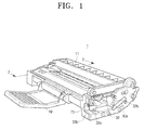
- FIG. 1 is a perspective view illustrating a developing cartridge 1 usable with an image forming apparatus according to an embodiment.
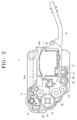
- FIG. 2 illustrates a sectional view of the developing cartridge 1 of FIG. 1 taken along a line 2-2 in FIG.1 .
- the developing cartridge 1 may include a housing 11, an image carrier 12, a developing member 13, a developer-storing portion 20, and a mounting portion 30.
- the housing 11 forms the outer appearance of the developing cartridge 1 and may rotatably support the image carrier 12 and the developing member 13.
- a folding handle 19 may be disposed at a side of the housing 11. The folding handle 19 may be used when the developing cartridge 1 is mounted into and removed from the image forming apparatus 100 (see FIG. 3 ).
- a first mounting history indicating member 40 may be disposed at the front end of the housing 11.
- a controller 170 see FIG.
- the image forming apparatus 100 uses the first mounting history indicating member 40 of the developing cartridge 1 to determine whether the developing cartridge 1 mounted in there is a new one or a used one.
- a fuse may be used as the first mounting history indicating member 40.
- the image carrier 12 is rotatably disposed in the from portion of the housing 11.
- the image carrier 12 may be provided separately outside the housing 11.
- An opening 15 through which a portion of the image carrier 12 is exposed may be formed at the housing 11 in from of the image carrier 12.
- the image carrier 12 may face a transfer roller 140 via the opening 15.
- Image carrier-cleaning unit 16 for removing waste developer remaining on the image carrier 12, and charging roller 17 for charging the surface of the image carrier 12 may also be disposed above the image carrier 12.
- the image carrier 12 is disposed integrally with the developing cartridge 1.
- the image carrier 12 (as well as the image carrier-cleaning unit 16 and/or charging roller 17) may be disposed in the image forming apparatus 100 separately from the developing cartridge 1.
- the developing member 13 supplies the image carrier 12 with developer from the developer-storing portion 20.
- a developing roller is used as the developing member 13.
- the developing roller 13 is rotatably disposed in the housing 11 nearby the image carrier 12.
- a developer-supplying roller 14 may be disposed between the developing roller 13 and the developer-storing portion 20.
- the developer-storing portion 20 is formed inside the housing 11 to store a predetermined amount of developer.
- the developer-storing portion 20 may store an amount of developer sufficient for printing a number of sheets of printing media.
- the developer-storing portion 20 may store enough amount of developer for printing, e.g., approximately 1000 pages of A4 paper at, e.g., 5 % print coverage. Because the developing cartridge 1 usable with the image forming apparatus according to an embodiment has a predetermined amount of developer in the developer-storing portion 20, even when the developing cartridge 1 is set up as shown in FIG.. 1 , i.e. with no developer cartridge 50 installed therein, it can still perform normal printing operations.
- test printing operations may be performed by the manufacturer of the developing cartridge by supplying the developing cartridge with a small amount of developer, which may be referred to as a pre-charged developer.
- the amount of developer in the pre-charged developer may be sufficient to print approximately 5 ⁇ 30 sheets of A4 size paper at, e.g., 5% print coverage.
- At least one supply developer-conveying member 21 and 22 may be disposed in the developer-storing portion 20 of the developing cartridge 1 to convey and/or circulate the developer stored in the developer-storing portion 20.
- two supply developer-conveying members 21 and 22 are disposed side by side in the developer-storing portion 20.
- a helical roller or screw may be used as either or both of the supply developer-conveying member 21 and 22.
- the mounting portion 30 is formed above the developer-storing portion 20 in the housing 11.
- the mounting portion 30 may be formed in various shapes as long as the mounting portion 30 can allow the developer cartridge 50 to be fixed to the developing cartridge 1.
- the mounting portion 30 is formed substantially as a cavity or chamber that extends inwardly from an outer surface of the housing 11. As illustrated in FIG. 1 , an entrance 30a of the mounting portion 30 is formed at the surface of the housing 11 such that the developer cartridge 50 can be mounted parallel with the developing roller 13.
- a power-transmitting member (not illustrated) to rotate a discharge developer-conveying member 53 (see FIG. 6 ) ofthe developer cartridge 50 may be disposed at a bottom of the mounting portion 30.
- a connecting member 31 may be disposed on the bottom surface of the mounting portion 30 adjacent to the developer-storing portion 20.
- the connecting member 31 fluidly communicates the developer-storing portion 20 with the developer cartridge 50. Therefore, when the developer cartridge 50 is mounted into the mounting portion 30 of the developing cartridge 1, an outlet 55 (see FIG. 6 ) of the developer cartridge 50 is in fluid communication with the connecting member 31.
- the connecting member 31 may be configured so that when no developer cartridge 50 is mounted into the developing cartridge 1, the connecting member 31 is closed, and when the developer cartridge 50 is mounted into the developing cartridge 1, the connecting member 31 is open. Structures with which the developer cartridge 50 may cause the connecting member 31 to be opened and closed are well-known, and the detailed description thereof is unnecessary.
- One or more mounting guiding groove 32a and 32b may be formed in the mounting portion 30 of the developing cartridge 1 to guide the developer cartridge 50 to be mounted. Furthermore, the developer cartridge 50 may have one or more mounting guide 59a and 59b corresponding to the mounting guiding groove 32a and 32b formed in the mounting portion 30. In this embodiment, as illustrated in FIGS. 1 and 2 , two mounting guiding grooves 32a and 32b are formed on opposite sides ofthe mounting portion 30 and the developer cartridge 50 has two mounting guides 59a and 59b corresponding to the two mounting guiding grooves 32a and 32b.
- FIG. 3 is a sectional view schematically illustrating the image forming apparatus 100 in which the developing cartridge 1 according to an embodiment of aspects of the present invention is mounted.
- the image forming apparatus 100 may include a main casing 110, a printing medium feeding unit 120, an exposure unit 130, the developing cartridge 1, the transfer roller 140, a fixing unit 150, a discharging roller 160, and a controller 170.
- the main casing 110 defines the outer appearance of the image forming apparatus 100, and may house and support the printing medium feeding unit 120, the exposure unit 130, the developing cartridge 1, the transfer roller 140, the fixing unit 150, the discharging roller 160, and the controller 170.
- the printing medium feeding unit 120 stores printing media P, and picks up the printing media P one by one to feed the printing medium P to the devebping cartridge 1.
- a pickup roller 121 is disposed at a leading end of the printing medium feeding unit 120.
- the exposure unit 130 may emit light, e.g., a laser beam, corresponding to print data to form electrostatic latent images on the image carrier 12, which may be provided in the developing cartridge 1.
- light e.g., a laser beam
- the developing cartridge 1 stores a quantity of developer, and develops the electrostatic latent images formed on the image carrier 12 into visible developer images.
- the developing cartridge 1 may be detachably mounted into the main casing 110.
- the developing cartridge 1 receives a motional power from a driving apparatus (not illustrated) disposed inside the main casing 110 so that the image carrier 12, the developing roller 13, and the supply developer-conveying members 21 and 22 may operationally move, e.g., rotate.
- a driving apparatus not illustrated
- the transfer roller 140 causes the visible developer images formed on the image carrier 12 to be transferred onto the printing media P.
- the fixing unit 150 causes the developer images transferred onto the printing media P to be fixed onto the printing media P.
- the discharging roller 160 discharges the printing media P having the developer images fixed thereon out of the image forming apparatus 100.
- the controller 170 uses the first mounting history indicating member 40 of the developing cartridge 1 to determine whether the mounted developing cartridge 1 is a new one, i.e., which has not previously been used, or a used one. If the developing cartridge 1 is a new one, the controller 170 remembers the number of pages that can be printed by using the developer stored in the developer-storing portion 20 as the total number of pages that can be printed. The controller 170 may additionally determine whether the developer cartridge 50 is mounted into the developing cartridge 1. When the developer cartridge 50 is mounted into the developing cartridge 1, the controller 170 adds the number of pages that can be printed by using the supplementary developer stored in the developer cartridge 50, setting the combined number of pages as the total number of pages that can be printed.
- the controller 170 adds the first number of pages that can be printed by using the developer stored in the developer-storing portion 20 of the developing cartridge 1 to the second number of pages that can be printed by using the supplementary developer stored in the developer cartridge 50 to get the sum thereof, and then, remembers the sum as the total number of pages that can be printed.
- the controller 170 may also control various components of the image forming apparatus, e.g., one or more of the printing medium feeding unit 120, the exposure unit 130, the developing cartridge 1, the transfer roller 140, the fixing unit 150, and the discharging roller 160, to control the printing operations.
- the controller 170 may be, e.g., a microprocessor, a microcontroller or the like, that includes a CPU to execute one or more computer instructions to implement the various control operations herein described, and may further include a memory device, e.g., a Random Access Memory (RAM), Read-Only-Memory (ROM), a flash memory, or the like, to store the one or more computer instructions.
- RAM Random Access Memory
- ROM Read-Only-Memory
- flash memory or the like
- the controller 170 determines whether the developing cartridge 1 is a new one by using the first mounting history indicating member 40. When the mounted developing cartridge 1 is a new one, the controller 170 reads the number of pages that can be printed corresponding to the mounted developing cartridge 1 previously stored in a memory (not illustrated), and sets the number of pages as the total number of pages that can be printed. In one embodiment, the number of pages that can be printed may be based on the amount of developer stored in the developer-storing portion 20 of the developing cartridge 1.
- the controller 170 may determine the number of pages to be printed taking into account the number of pages that the image forming apparatus 100 has printed since the time the developing cartridge 1 is mounted. Accordingly, the controller 170 is capable to determine whether the number of pages to be printed reaches the number of pages that can be printed by using the mounted developing cartridge 1.
- the controller 170 may perform an operation on the first mounting history indicating member 40 in order to recognize when the same developing cartridge 1 is later separated and remounted after the initial mounting. For example, in an embodiment, in which a fuse is used as the first mounting history indicating member 40, when a new developing cartridge 1 is mounted into the case 110, the controller 170 may sense current flowing through the fuse, and make the determination that the mounted developing cartridge 1 is new, and then, may apply a sufficient amount of current to blow the fuse. Accordingly, when the same developing cartridge 1 is remounted into the image forming apparatus 100, the controller 170 may recognize the mounted developing cartridge 1 is not new by the fact that no current flows in the fuse. As a result, when a used developing cartridge 1 is mounted, the controller 170 can determine that the mounted developing cartridge 1 has already been used. The controller 170 may then determine the number of pages that can be printed based on whether the mounted developing cartridge 1 is new or used.
- the controller 170 of the image forming apparatus 100 may control the exposure unit 130 to emit a laser beam to form electrostatic latent images corresponding to the printing data on the image carrier 12 of the developing cartridge 1.
- the developing roller 13 of the developing cartridge 1 supplies the developer to the image carrier 12 to develop the electrostatic latent images into visible developer images. Because the developing cartridge 1 according to an embodiment may have an amount of developer in the developer-storing portion 20 thereof, even when the developer cartridge 50 is not mounted to the developing cartridge 1, the developing cartridge 1 can still develop the electrostatic latent images on the image carrier 12.
- the controller 170 may also control the printing medium feeding unit 120 to pick up and feed a printing medium P between the transfer roller 140 and the image carrier 12 of the developing cartridge 1. Then, the developer images may be transferred from the image carrier 12 onto the printing medium P.
- the fixing unit 150 While the printing medium P having the developer images transferred thereon passes through the fixing unit 150, the developer images transferred onto the printing medium P are fixed onto the printing medium P. Then, the discharging roller 160 discharges the printing medium P out of the image forming apparatus 100.
- the controller 170 of the image forming apparatus 100 may keep track of the number of printed pages that has been printed. The controller 170 may continue to perform the printing operations until the number of printed pages reaches the total number of pages that can be printed.
- the image forming apparatus 100 may be operable, and may print up to a number of pages.
- the controller 170 of the image forming apparatus 100 may alert the fact that the developer supply has been exhausted. A user upon being so alerted may separate the developing cartridge 1 from the image forming apparatus 100, mount a developer cartridge 50 into the mounting portion 30 of the developing cartridge 1, and then reinstall the developing cartridge 1 with the developer cartridge 50 in the image forming apparatus 100.
- FIG. 4 is a perspective view illustrating the developer cartridge 50 capable of being mounted to the developing cartridge 1 according to an embodiment.
- FIG. 5 is a perspective view illustrating the developing cartridge 1 usable with an image forming apparatus according to an embodiment, to which the developer cartridge 50 of FIG. 4 is mounted.
- FIG. 6 is a sectional view illustrating the developing cartridge 1 of FIG. 5 .
- the developer cartridge 50 is formed substantially in a rectangular parallelepiped shape.
- a developer-receiving portion 51 in which a predetermined amount of supplementary developer is stored is formed inside the developer cartridge 50.
- the discharge developer-conveying member 53 may be rotatably disposed in the developer-receiving portion 51.
- the developer-receiving portion 51 may be formed to store the amount of developer more than the amount of developer stored in the developer-storing portion 20 of the developing cartridge 1.
- the developer-receiving portion 51 of the developer cartridge 50 may be formed to store an amount of developer capable of printing approximately 2000 ⁇ 3000 pages of A4 paper at 5 % average print coverage.
- the developer cartridge 50 may be formed to be mounted into the developing cartridge 1 parallel with the lengthwise direction of the developing cartridge 1 or with the lengthwise direction of the developing roller 13. This structure and mounting direction may allow developer leakage to be minimized during mounting and removal of the developer cartridge 50 to and from the developing cartridge 1.
- the developer cartridge 50 may include one or more mounting guides 59a and 59b for mounting of the developer cartridge 50.
- the developer cartridge 50 has two mounting guides 59a and 59b disposed along the length of the developer cartridge 50.
- the two mounting guides 59a and 59b cooperate with the two mounting guiding grooves 32a and 32b formed in the mounting portion 30 of the developing cartridge 1, and thereby, when the developer cartridge 50 is pushed into the interior of the mounting portion 30, guide the developer cartridge 50 into the mounted position.
- the developer cartridge 50 may be mounted in the developing cartridge 1.
- the mounting portion 30 of the developing cartridge 1 into which the developer cartridge 50 is mounted may be formed substantially as a cavity or recess extending from the outer surface of the housing 11 into the interior of the developing cartridge 1, and may be formed such manner to allow the user to readily see the mounting location of the developer cartridge 50.
- the mounting guiding grooves 32a and 32b of the mounting portion 30 of the developing cartridge 1 guide the developer cartridge 50 during the mounting of the developer cartridge 50 so that the mounting the developer cartridge 50 into the developing cartridge 1 may be easier.
- a helical shaped screw or roller may be used as the discharge developer-conveying member 53.
- a waste developer-receiving portion 52 may be provided at adjacent to and parallel with the developer-receiving portion 51 (see FIG. 6 ). The waste developer-receiving portion 52 may receive waste developer removed from the image carrier 12 by the image carrier-cleaning unit 16.
- An outlet 55 may be formed on the bottom surface of the developer cartridge 50.
- the developer stored in the developer-receiving portion 51 may be moved toward the outlet 55 by the discharge developer-conveying member 53, which may be then is discharged out of the developer cartridge 50 through the outlet 55.
- the outlet 55 may be configured so that when the developer cartridge 50 is mounted into the developing cartridge 1, the outlet 55 is opened by the connecting member 31 of the developing cartridge 1, and when the developer cartridge 50 is separated from the developing cartridge 1, the outlet 55 is closed. Accordingly, when the developer cartridge 50 is mounted into the mounting portion 30 of the developing cartridge 1, the outlet 55 of the developer cartridge 50 is in fluid communication with the connecting member 31 ofthe developing cartridge 1.
- a second mounting history indicating member 60 may also be disposed at a side of the developer cartridge 50 so that the controller 170 of the image forming apparatus 100 can determine whether the developer cartridge 50 is mounted in the developing cartridge 1.
- the second mounting history indicating member 60 is disposed on a side surface 54 of the developer cartridge 50 that is exposed outside when the developer cartridge 50 is mounted into the developing cartridge 1.
- the second mounting history indicating member 60 may use any proper device that can allow the controller 170 ofthe image forming apparatus 100 to detect the developer cartridge 50 mounted to the developing cartridge 1.
- an electrode plate may be used as the second mounting history indicating member 60, and the controller 170 of the image forming apparatus 100 may have a sensor capable of sensing the electrode plate.
- a locking unit 70 to lock the developer cartridge 50 to the developing cartridge 1 may be disposed at the side surface 54 of the developer cartridge 50 that is exposed outside when the developer cartridge 50 is mounted into the developing cartridge 1.
- the locking unit 70 as illustrated in FIG. 4 , may be rotatably hinged to a corner of the side surface 54 of the developer cartridge 50, and includes a locking portion 72 and a handle 71.
- the locking portion 72 may be formed to be hooked on a locking projection 73 formed on the developing cartridge 1.
- the locking projection 73 as illustrated in FIG. 1 , may project from the surface of a groove 30b formed in a side of the entrance 30a of the mounting portion 30 ofthe developing cartridge 1.
- the handle 71 may be formed to be angled approximately 90 degrees with respect to the locking portion 72 so that the user can grab the handle 71 and rotate the locking portion 72. Therefore, when the user rotates the handle 71 in a direction, the locking portion 72 hooks onto the locking projection 73 so that the developer cartridge 50 is locked in place in the developing cartridge 1.
- the locking portion 72 is removed from the locking projection 73 of the developing cartridge 1 so that the developer cartridge 50 can be released from the developing cartridge 1.
- An end of the handle 71 may be formed in a bent portion 71 a so that the user can easily grab the handle 71.
- the handle 71 may be formed of a material of different colour from the developer cartridge 50 so that when replacing the developer cartridge 50, the user can easily see the locking unit 70.
- FIG. 7 is a sectional view schematically illustrating the image forming apparatus 100 into which the developing cartridge 1 according to an exemplary embodiment of the present general inventive concept with the developer cartridge 50 of FIG. 4 is mounted.
- the image forming apparatus 100 may include the main casing 110, the printing medium feeding unit 120, the exposure unit 130, the developing cartridge 1, the transfer roller 140, the fixing unit 150, the discharging roller 160, and the controller 170.
- the image forming apparatus 100 illustrated in FIG. 7 is substantially the same as the image forming apparatus 100 illustrated in FIG. 3 as described above except that the developer cartridge 50 is mounted into the developing cartridge 1. Therefore, detailed descriptions of relevant components already described are unnecessary.
- the controller 170 of the image forming apparatus 100 determines whether the developing cartridge 1 is a new one by using the first mounting history indicating member 40 and whether the developer cartridge 50 is mounted into the developing cartridge 1 by using the second mounting history indicating member 60.
- the controller 170 reads the number of pages that can be printed corresponding to the developer cartridge 50 mounted into the developing cartridge 1 from a memory (not illustrated), and adds the number of pages corresponding to the developer cartridge 50 to the number of pages that can be printed, and sets the sum as the total number of pages that can be printed.
- the memory stores the number of pages that can be printed by using the supplementary developer stored in the developer-receiving portion 51 of the developer cartridge 50. Accordingly, for example, if the image forming apparatus 100 has already printed a number of pages corresponding to the amount of developer in the developing cartridge 1, the controller 170 may set only the number of pages corresponding to the amount of the supplementary developer stored in the developer cartridge 50 as the total number of pages that can be printed.
- the controller 170 of the image forming apparatus 100 may control the exposure unit 130 to emit a laser beam to form electrostatic latent images corresponding to the printing data on the image carrier 12 of the developing cartridge 1.
- the discharge developer-conveying member 53 of the developer cartridge 50 receives a rotational power from the driving apparatus (not illustrated) disposed in the image forming apparatus 100, and rotates.
- the discharge developer-conveying member 53 ofthe developer cartridge 50 rotates, the supplementary developer stored in the developer-receiving portion 51 of the developer cartridge 50 is moved toward the outlet 55, and is discharged therethrough.
- the developer discharged from the outlet 55 of the developer cartridge 50 enters the developer-storing portion 20 ofthe developing cartridge 1 through the connecting member 31.
- the two supply developer-conveying members 21 and 22 disposed in the developing cartridge 1 rotate to supply the developing roller 13 with the developer entering the developer-storing portion 20.
- the developing roller 13 ofthe developing cartridge 1 supplies the developer to the image carrier 12 to develop the electrostatic latent images into developer images.
- the developing cartridge 1 according to an embodiment can receive the supplementary developer from the developer cartridge 50 mounted to the mounting portion 30 so that even when the developer stored in the developer-storing portion 20 of the developing cartridge 1 runs out, the developing cartridge 1 is able to develop the electrostatic latent images on the image carrier 12 into the developer images.
- the controller 170 may control the printing medium feeding unit 120 to pick up and feed a printing medium P between the transfer roller 140 and the image carrier 12 of the developing cartridge 1. Then, the developer image is transferred from the image carrier 12 to the printing medium P.
- the fixing unit 150 While the printing medium P having the developer images transferred thereon passes through the fixing unit 150, the developer image is fixed onto the printing medium P. Then, the discharging roller 160 discharges the printing medium P out of the image forming apparatus 100.
- the controller 170 of the image forming apparatus 100 may continue to count the number of printed pages.
- the controller 170 keeps performing the printing operation until the number of printed pages reaches the total number of pages that can be printed.
- the developing cartridge 1 usable with an image forming apparatus according to an embodiment, although the developer stored in the developing cartridge 1 is completely consumed, when the developer cartridge 50 is mounted, the developing cartridge 1 can be supplied with the supplementary developer from the developer cartridge 50, and can print a number of other pages.
- the developer cartridge 50 having the supplementary developer is mounted into the developing cartridge 1.
- this does not limit the timing of the developer cartridge 50 being mounted into the developing cartridge 1.
- the new developing cartridge 1 having the developer cartridge 50 may be disposed in the image forming apparatus 100.
- a new developing cartridge 1 with no developer cartridge 50 is mounted into the image forming apparatus 100, and then the new developing cartridge 1 may be separated from the image forming apparatus 100 before the developer stored in the developing cartridge 1 is completely consumed.
- a developer cartridge 50 is mounted into the separated developing cartridge 1, and then the developing cartridge 1 with the developer cartridge 50 again may be disposed in the image forming apparatus 100.
- FIGS. 8 and 9 are flowcharts illustrating printing methods that may be practiced in an image forming apparatus 100 according to an embodiment of the present invention.
- FIG. 8 illustrates a method that may be implemented using the image forming apparatus 100 when the developing cartridge 1 with no developer cartridge 50 is mounted into the image forming apparatus 100 as illustrated in FIG. 3 .
- the image forming apparatus 100 uses the developer stored in the developer-storing portion 20 of the developing cartridge 1 with no developer cartridge 50 to perform a printing operation (S 11). Then, the user separates the developing cartridge 1 from the image forming apparatus 100, and mounts a developer cartridge 50 into the separated developing cartridge 1 (S12). At this time, as illustrated in FIG. 5 , the user uses the locking unit 70 to lock the developer cartridge 50 to the developing cartridge 1. After that, the user again mounts the developing cartridge 1 in which the developer cartridge 50 is mounted into the image forming apparatus 100. Then, the image forming apparatus 100 uses the developer stored in the developer cartridge 50 to perform a printing operation (S 13).
- FIG. 9 illustrates a method that may be implemented using the image forming apparatus 100 when the developing cartridge 1 with a developer cartridge 50, as illustrated in FIG. 7 , is mounted into the image forming apparatus 100.
- the user mounts the developer cartridge 50 into the developing cartridge 1 (S21).
- the user uses the locking unit 70 to lock the developer cartridge 50 to the developing cartridge 1.
- the user mounts the developing cartridge 1 into which the developer cartridge 50 is mounted into the image forming apparatus 100 (S22).
- the image forming apparatus 100 performs a printing operation using the developer stored in the developer-storing portion 20 of the developing cartridge 1 (S23).
- the image forming apparatus 100 performs the printing operation using the developer stored in the developer cartridge 50 (S24).
- the user When the developer in the developer cartridge 50 is completely consumed during the printing operation, the user separates the developing cartridge 1 from the image forming apparatus 100.
- the empty developer cartridge 50 is separated from the separated developing cartridge 1, and is replaced with a new developer cartridge 50.
- the user rotates the handle 71 of the locking unit 70 locking the developer cartridge 50, as illustrated in FIG. 5 , so that the locking portion 72 of the locking unit 70 is disengaged from the locking projection 73, allowing the developer cartridge 50 to be separated from the developing cartridge 1.
- the user mounts a new developer cartridge 50 into the developing cartridge 1, and locks the new developer cartridge 50 to the developing cartridge 1 using the locking unit 70.
- the image forming apparatus 100 continues to perform a printing operation.
- the developing cartridge 1 can be sold in a state that the developer cartridge 50 is mounted into the developing cartridge 1. That is, developing cartridge 1 can be sold separately from the developer cartridge 50, differently from the conventional developing cartridge.
- the user can buy a new developer cartridge 50, which is sold separately from the developing cartridge 1, and mount the new developer cartridge 50 into the used developing cartridge 1 to continue to use the used developing cartridge 1.
Landscapes
- Physics & Mathematics (AREA)
- General Physics & Mathematics (AREA)
- Engineering & Computer Science (AREA)
- Computer Vision & Pattern Recognition (AREA)
- Dry Development In Electrophotography (AREA)
- Electrophotography Configuration And Component (AREA)
Claims (10)
- Appareil de formation d'images comportant : une cartouche (1) de développement montée de façon détachable dans un appareil (100) de formation d'images, comportant :un support (12) d'image et un élément (13) de développement soutenu dans un boîtier (11) de la cartouche (1) de développement, l'élément (13) de développement étant configuré pour développer une image latente électrostatique formée sur le support (12) d'image en donnant une image visible de révélateur ;une partie (30) de montage formée dans le boîtier (11), la partie (30) de montage étant configurée pour loger de façon amovible dans celle-ci une cartouche (50) de révélateur supplémentaire contenant une quantité supplémentaire de révélateur, etune partie (20) de stockage de révélateur aménagée dans le boîtier (11),un élément (31) de raccordement étant formée dans le boîtier (11), l'élément (31) de raccordement étant configuré pour définir un passage de communication fluidique entre la partie (20) de stockage de révélateur et la partie (30) de montage et comprenant un couvercle disposé de façon à fermer l'élément (31) de raccordement, le couvercle étant configuré pour être en contact avec serrage avec au moins une partie de la cartouche (50) de révélateur supplémentaire lorsque la cartouche (50) de révélateur supplémentaire est montée dans la partie (30) de montage de telle façon que le couvercle s'ouvre, et le couvercle étant libéré du contact avec serrage lorsque la cartouche (50) de révélateur supplémentaire est retirée de la partie (30) de montage de telle façon que le couvercle se ferme, de telle sorte que, lorsque la cartouche (50) de révélateur supplémentaire est montée dans la partie (30) de montage, la quantité supplémentaire de révélateur puisse être reçue dans la partie (20) de stockage de révélateur en provenance de la cartouche (50) de révélateur supplémentaire via l'élément (31) de raccordement ; etla partie (20) de stockage de révélateur étant configurée pour stocker une première quantité de révélateur, la cartouche (1) de développement étant configurée pour alimenter d'abord l'élément (13) de développement en révélateur issu de la première quantité de révélateur stockée dans la partie (20) de stockage de révélateur, la cartouche (50) de révélateur supplémentaire étant prévue pour être montée dans la partie (30) de montage, et la cartouche (50) de révélateur supplémentaire comportant :un élément indicateur (60) d'historique de montage placé sur la cartouche (50) de révélateur supplémentaire pour indiquer si la cartouche (50) de révélateur supplémentaire est montée dans la partie de montage ; et l'appareil (100) de formation d'images comportant :une commande (170) configurée pour déterminer si la cartouche (50) de révélateur supplémentaire est montée dans la partie (30) de montage, et pour faire en sorte que l'élément (13) de développement soit alimenté en révélateur issu de la première quantité de révélateur de la partie (20) de stockage de révélateur s'il est déterminé que la cartouche amovible (50) de révélateur n'est pas montée dans la partie (30) de montage ;la commande étant configurée pour faire en sorte, s'il est déterminé que la cartouche amovible de révélateur supplémentaire est montée dans la partie de montage, que l'élément de développement soit alimenté en révélateur reçu en provenance de la cartouche amovible de révélateur supplémentaire lorsque la première quantité de révélateur provenant de la partie de stockage de révélateur est sensiblement épuisée d'après le nombre d'opérations d'impression qui peuvent être effectuées compte tenu de la quantité de révélateur disponible à partir de la partie de stockage de révélateur.
- Appareil de formation d'images selon la revendication 1, la partie (30) de montage s'étendant vers l'intérieur jusque dans le boîtier parallèlement à l'élément (13) de développement.
- Appareil de formation d'images selon la revendication 1 ou 2, la partie (30) de montage comportant :au moins une rainure (32) de guidage de montage servant à guider la cartouche (50) de révélateur supplémentaire pendant le montage de la cartouche (50) de révélateur supplémentaire dans la partie (30) de montage.
- Appareil de formation d'images selon la revendication 1, 2 ou 3, la cartouche de révélateur supplémentaire comportant en outre une unité de blocage formée sur celle-ci, l'appareil de formation d'images comportant une protubérance (73) de blocage formée sur le boîtier (11) au voisinage de la partie (30) de montage, la protubérance (73) de blocage étant configurée pour coopérer avec l'unité (70) de blocage de la cartouche (50) de révélateur supplémentaire pour bloquer la cartouche (50) de révélateur supplémentaire en place lorsque la cartouche (50) de révélateur supplémentaire est montée dans la partie (30) de montage.
- L'appareil de formation d'images selon l'une quelconque des revendications précédentes, comportant en outre :un autre élément indicateur d'historique de montage (40) possédant un état caractéristique qui est susceptible d'être modifié pour indiquer si la cartouche (1) de développement a été montée auparavant.
- Appareil de formation d'images selon la revendication 1, l'élément indicateur (60) d'historique de montage étant disposé sur une surface de la cartouche amovible (50) de révélateur supplémentaire qui est au moins partiellement exposée lorsque la cartouche (50) de révélateur supplémentaire est montée dans la partie (30) de montage de la cartouche (1) de développement.
- Appareil de formation d'images selon la revendication 1, la cartouche (50) de révélateur supplémentaire comportant :une partie réceptrice (51) de révélateur formée à l'intérieur de la cartouche (50) de révélateur supplémentaire pour stocker une quantité de révélateur supplémentaire ;une sortie (55) formée dans la cartouche (50) de révélateur supplémentaire, la sortie (55) étant, lorsque la cartouche (50) de révélateur supplémentaire est montée dans la partie (30) de montage de la cartouche (1) de développement, en communication fluidique avec une partie (20) de stockage de révélateur de la cartouche (1) de développement, la partie (20) de stockage de révélateur constituant un stockage pour une quantité de révélateur ; etun élément (53) d'acheminement de révélateur disposé de façon tournante à l'intérieur de la partie réceptrice (51) de révélateur, l'élément (53) d'acheminement de révélateur étant, lorsque la cartouche (50) de révélateur supplémentaire est montée dans la partie (30) de montage de la cartouche (1) de développement, commandé par une commande (170) de l'appareil de formation d'images pour acheminer le révélateur supplémentaire vers la cartouche (1) de développement à travers la sortie (55) après que la quantité de révélateur stockée dans la partie (20) de stockage de révélateur de la cartouche (1) de développement a été épuisée.
- Appareil de formation d'images selon la revendication 1, l'élément indicateur (60) d'historique de montage comportant une plaque d'électrode susceptible d'être détectée par l'appareil (100) de formation d'images.
- Appareil de formation d'images selon la revendication 7, la cartouche (50) de révélateur supplémentaire comportant en outre :une partie réceptrice (52) de révélateur usé formée dans la cartouche (50) de révélateur supplémentaire au voisinage de la partie réceptrice (51) de révélateur, la partie réceptrice (52) de révélateur usé constituant un espace de collecte servant à stocker du révélateur usé reçu en provenance de la cartouche (1) de développement.
- Appareil de formation d'images selon la revendication 7, la cartouche (50) de révélateur supplémentaire comportant en outre :au moins un guide (59) de montage formé sur la cartouche (50) de révélateur supplémentaire, le ou les guides (59) de montage étant configurés pour correspondre à, et pour coopérer avec, au moins une rainure (32) de guidage de montage formée dans la partie (30) de montage de la cartouche (1) de développement afin de guider la cartouche (50) de révélateur supplémentaire en place pendant le montage de la cartouche (50) de révélateur supplémentaire dans la partie (30) de montage.
Applications Claiming Priority (1)
| Application Number | Priority Date | Filing Date | Title |
|---|---|---|---|
| KR1020080016459A KR100892110B1 (ko) | 2008-02-22 | 2008-02-22 | 현상 카트리지, 이를 구비한 화상형성장치, 및화상형성장치의 인쇄방법 |
Publications (2)
| Publication Number | Publication Date |
|---|---|
| EP2093619A1 EP2093619A1 (fr) | 2009-08-26 |
| EP2093619B1 true EP2093619B1 (fr) | 2013-12-25 |
Family
ID=40467110
Family Applications (1)
| Application Number | Title | Priority Date | Filing Date |
|---|---|---|---|
| EP09150141.1A Ceased EP2093619B1 (fr) | 2008-02-22 | 2009-01-07 | Appareil de formation d'images |
Country Status (6)
| Country | Link |
|---|---|
| US (1) | US8155558B2 (fr) |
| EP (1) | EP2093619B1 (fr) |
| KR (1) | KR100892110B1 (fr) |
| CN (1) | CN101515136B (fr) |
| BR (1) | BRPI0805358A2 (fr) |
| RU (1) | RU2390420C1 (fr) |
Families Citing this family (19)
| Publication number | Priority date | Publication date | Assignee | Title |
|---|---|---|---|---|
| JP4919124B2 (ja) | 2010-03-31 | 2012-04-18 | ブラザー工業株式会社 | カートリッジ |
| JP5115607B2 (ja) * | 2010-08-31 | 2013-01-09 | ブラザー工業株式会社 | キャップおよびカートリッジ |
| JP5884436B2 (ja) | 2011-11-24 | 2016-03-15 | ブラザー工業株式会社 | カートリッジ |
| JP5984577B2 (ja) * | 2012-08-21 | 2016-09-06 | キヤノン株式会社 | カートリッジ |
| JP6127779B2 (ja) | 2013-06-28 | 2017-05-17 | ブラザー工業株式会社 | カートリッジ |
| JP6102573B2 (ja) | 2013-06-28 | 2017-03-29 | ブラザー工業株式会社 | カートリッジ |
| JP6060866B2 (ja) | 2013-09-20 | 2017-01-18 | ブラザー工業株式会社 | 画像形成装置 |
| JP6064867B2 (ja) | 2013-10-31 | 2017-01-25 | ブラザー工業株式会社 | カートリッジ |
| JP5991311B2 (ja) * | 2013-12-20 | 2016-09-14 | コニカミノルタ株式会社 | ユニット搭載装置、ユニット搭載装置の制御方法、およびユニット搭載装置の制御プログラム |
| JP6136938B2 (ja) | 2014-01-06 | 2017-05-31 | ブラザー工業株式会社 | 現像カートリッジ |
| JP6221905B2 (ja) | 2014-03-31 | 2017-11-01 | ブラザー工業株式会社 | カートリッジ |
| JP6137028B2 (ja) | 2014-03-31 | 2017-05-31 | ブラザー工業株式会社 | カートリッジ |
| JP6137027B2 (ja) | 2014-03-31 | 2017-05-31 | ブラザー工業株式会社 | カートリッジ |
| JP6079688B2 (ja) | 2014-03-31 | 2017-02-15 | ブラザー工業株式会社 | カートリッジ |
| JP6135583B2 (ja) | 2014-03-31 | 2017-05-31 | ブラザー工業株式会社 | カートリッジ |
| JP6137029B2 (ja) | 2014-03-31 | 2017-05-31 | ブラザー工業株式会社 | カートリッジ |
| JP6079687B2 (ja) | 2014-03-31 | 2017-02-15 | ブラザー工業株式会社 | カートリッジ |
| JP6645332B2 (ja) * | 2016-04-18 | 2020-02-14 | 京セラドキュメントソリューションズ株式会社 | 画像形成装置 |
| JP7039226B2 (ja) | 2017-09-21 | 2022-03-22 | キヤノン株式会社 | 現像剤補給容器及び現像剤補給システム |
Citations (1)
| Publication number | Priority date | Publication date | Assignee | Title |
|---|---|---|---|---|
| EP1548519A2 (fr) * | 2003-12-23 | 2005-06-29 | Sagem SA | Système de cartouche à recharge de toner et son procédé de mise en oeuvre |
Family Cites Families (47)
| Publication number | Priority date | Publication date | Assignee | Title |
|---|---|---|---|---|
| JPS60238873A (ja) | 1984-05-11 | 1985-11-27 | Fuji Xerox Co Ltd | トナ−補給装置 |
| US4668287A (en) | 1985-09-26 | 1987-05-26 | Westinghouse Electric Corp. | Process for producing high purity zirconium and hafnium |
| US4974020A (en) | 1986-09-30 | 1990-11-27 | Mita Industrial Co. | Removable developing units for a copying machine and display for indicating the useful life of the machine |
| JPS6491164A (en) | 1987-10-02 | 1989-04-10 | Ricoh Kk | Developing device |
| US4967234A (en) | 1987-11-10 | 1990-10-30 | Ricoh Company, Ltd. | Image forming apparatus |
| JP2965041B2 (ja) | 1988-11-08 | 1999-10-18 | 株式会社リコー | 画像形成装置 |
| US5493366A (en) | 1990-09-07 | 1996-02-20 | Konica Corporation | Image forming apparatus |
| JP3060725B2 (ja) | 1992-06-30 | 2000-07-10 | 富士通株式会社 | 現像剤カ−トリッジ及びこれを用いた画像形成装置 |
| JP3244992B2 (ja) | 1994-03-15 | 2002-01-07 | キヤノン株式会社 | 電子写真画像形成装置 |
| JP3263533B2 (ja) | 1994-05-17 | 2002-03-04 | ブラザー工業株式会社 | トナー残量検出装置及びそのトナー収納装置 |
| JPH0922177A (ja) | 1995-07-04 | 1997-01-21 | Canon Inc | トナーカートリッジ、プロセスカートリッジ、トナーホッパー及び画像形成装置 |
| JPH10142910A (ja) | 1996-11-08 | 1998-05-29 | Katsuragawa Electric Co Ltd | トナー供給方式 |
| JP3037194B2 (ja) | 1997-04-25 | 2000-04-24 | 新潟日本電気株式会社 | プロセスカートリッジへのトナーの供給方法及び画像形成装置用プロセスカートリッジ |
| US6968139B2 (en) | 1997-06-19 | 2005-11-22 | Canon Kabushiki Kaisha | Toner supply container and electrophotographic image forming apparatus |
| JPH1124513A (ja) | 1997-06-27 | 1999-01-29 | Canon Inc | トナー補給装置及び電子写真画像形成装置 |
| US5930238A (en) * | 1997-07-10 | 1999-07-27 | General Datacomm | Asynchronous transfer mode (ATM) multicast tree delivery switching |
| JP3408166B2 (ja) | 1997-09-30 | 2003-05-19 | キヤノン株式会社 | トナー供給容器及び電子写真画像形成装置 |
| JP3321728B2 (ja) | 1997-11-06 | 2002-09-09 | 京セラミタ株式会社 | 画像形成機のトナー補給装置およびこれに用いるトナーカートリッジ |
| JP3721749B2 (ja) | 1997-11-12 | 2005-11-30 | コニカミノルタビジネステクノロジーズ株式会社 | 画像形成装置のユニットおよびそのユニットを用いる画像形成装置および画像形成装置のユニット検出装置および画像形成装置のユニット検出方法 |
| JP3604919B2 (ja) | 1998-08-31 | 2004-12-22 | キヤノン株式会社 | カラー電子写真画像形成装置及び現像カートリッジ |
| JP3627528B2 (ja) | 1998-09-02 | 2005-03-09 | 富士ゼロックス株式会社 | 現像装置 |
| JP4054521B2 (ja) | 1999-11-29 | 2008-02-27 | キヤノン株式会社 | 現像剤補給カートリッジ及び現像剤補給システム |
| DE10043016B4 (de) | 2000-09-01 | 2006-11-23 | Walter Ag | Bohrnutenfräser |
| KR100362390B1 (ko) | 2000-12-29 | 2002-11-23 | 삼성전자 주식회사 | 화상형성장치의 현상기-토너 카트리지 조립체 |
| US6751428B2 (en) | 2001-09-13 | 2004-06-15 | Brother Kogyo Kabushiki Kaisha | Image forming device and detachably loaded process unit |
| JP3534104B2 (ja) | 2001-12-20 | 2004-06-07 | 富士ゼロックス株式会社 | 画像形成装置及びこれに用いられるプロセスカートリッジ、現像装置 |
| JP3982346B2 (ja) | 2002-06-28 | 2007-09-26 | コニカミノルタビジネステクノロジーズ株式会社 | 画像形成装置のトナーカートリッジ |
| JP2004170955A (ja) | 2002-11-08 | 2004-06-17 | Canon Inc | 画像形成装置及びカートリッジ、画像形成システム、カートリッジ用メモリ媒体 |
| JP4242667B2 (ja) | 2003-02-28 | 2009-03-25 | 株式会社東芝 | トナーカートリッジ及び画像形成装置 |
| US7076179B2 (en) | 2003-03-20 | 2006-07-11 | Seiko Epson Corporation | Image forming apparatus and a storage controlling method for information on an improper detachment of developer cartridge to be written in a cartridge storage means |
| JP4455197B2 (ja) * | 2003-07-31 | 2010-04-21 | キヤノン株式会社 | 画像形成装置 |
| US6915090B2 (en) * | 2003-08-07 | 2005-07-05 | Kabushiki Kaisha Toshiba | Image forming apparatus that determines toner amount in a plurality of color cartridges |
| JP3673793B2 (ja) | 2003-08-29 | 2005-07-20 | キヤノン株式会社 | プロセスカートリッジ、プロセスカートリッジの装着機構及び電子写真画像形成装置 |
| JP4378221B2 (ja) | 2003-10-08 | 2009-12-02 | キヤノン株式会社 | プロセスカートリッジ及び電子写真画像形成装置 |
| KR100553897B1 (ko) | 2003-10-31 | 2006-02-24 | 삼성전자주식회사 | 메모리를 이용한 화상형성장치의 소모품 관리 장치 |
| JP2005195843A (ja) | 2004-01-07 | 2005-07-21 | Seiko Epson Corp | カラー印刷モードとモノクロ印刷モードを切り替え可能にした画像形成装置 |
| JP4525167B2 (ja) | 2004-05-14 | 2010-08-18 | 富士ゼロックス株式会社 | 現像剤回収機構及び画像形成装置 |
| JP4650780B2 (ja) * | 2004-05-17 | 2011-03-16 | 富士ゼロックス株式会社 | 交換ユニットが装着された画像形成装置、画像形成システム及び画像形成装置の制御方法 |
| JP2005338329A (ja) | 2004-05-26 | 2005-12-08 | Fuji Xerox Co Ltd | プロセスカートリッジ及び画像形成装置 |
| KR20060034168A (ko) | 2004-10-18 | 2006-04-21 | 삼성전자주식회사 | 화상형성기기의 상형성장치 |
| KR100677595B1 (ko) | 2005-06-10 | 2007-02-02 | 삼성전자주식회사 | 현상기 및 이를 채용한 칼라화상형성장치 |
| JP4315933B2 (ja) | 2005-07-21 | 2009-08-19 | 株式会社沖データ | 現像剤カートリッジ、現像装置、及び画像形成装置 |
| KR20070016890A (ko) * | 2005-08-05 | 2007-02-08 | 삼성전자주식회사 | 토너공급장치 및 이를 구비한 화상형성장치 |
| JP4687387B2 (ja) * | 2005-10-26 | 2011-05-25 | ブラザー工業株式会社 | 画像形成装置及び作像カートリッジ |
| KR100788672B1 (ko) * | 2005-11-04 | 2007-12-26 | 삼성전자주식회사 | 화상형성장치 및 화상형성장치의 인쇄 방법 |
| JP4681489B2 (ja) | 2006-03-31 | 2011-05-11 | 株式会社沖データ | トナーカートリッジ、現像装置、及び画像形成装置 |
| JP4710760B2 (ja) | 2006-08-29 | 2011-06-29 | 富士ゼロックス株式会社 | 現像剤搬送装置および画像形成装置 |
-
2008
- 2008-02-22 KR KR1020080016459A patent/KR100892110B1/ko not_active Expired - Fee Related
- 2008-08-28 US US12/200,013 patent/US8155558B2/en not_active Expired - Fee Related
- 2008-11-04 CN CN2008101743260A patent/CN101515136B/zh not_active Expired - Fee Related
- 2008-12-09 RU RU2008148636/12A patent/RU2390420C1/ru active
- 2008-12-10 BR BRPI0805358-8A patent/BRPI0805358A2/pt not_active Application Discontinuation
-
2009
- 2009-01-07 EP EP09150141.1A patent/EP2093619B1/fr not_active Ceased
Patent Citations (1)
| Publication number | Priority date | Publication date | Assignee | Title |
|---|---|---|---|---|
| EP1548519A2 (fr) * | 2003-12-23 | 2005-06-29 | Sagem SA | Système de cartouche à recharge de toner et son procédé de mise en oeuvre |
Also Published As
| Publication number | Publication date |
|---|---|
| US20090214227A1 (en) | 2009-08-27 |
| BRPI0805358A2 (pt) | 2009-10-06 |
| KR100892110B1 (ko) | 2009-04-08 |
| CN101515136A (zh) | 2009-08-26 |
| CN101515136B (zh) | 2013-02-27 |
| US8155558B2 (en) | 2012-04-10 |
| RU2390420C1 (ru) | 2010-05-27 |
| EP2093619A1 (fr) | 2009-08-26 |
Similar Documents
| Publication | Publication Date | Title |
|---|---|---|
| EP2093619B1 (fr) | Appareil de formation d'images | |
| US8582989B2 (en) | Image forming apparatus with replaceable developer holder | |
| EP2093626B1 (fr) | Dispositif de développement | |
| JP5370800B2 (ja) | 画像形成装置および現像剤充填方法 | |
| US20220146974A1 (en) | Image forming apparatus having a toner replenishment operation | |
| JP5870538B2 (ja) | 画像形成装置およびカートリッジ | |
| KR20210043470A (ko) | 카트리지, 보급 용기, 및 화상 형성 장치 | |
| CN102269959B (zh) | 图像形成装置以及图像形成装置的调色剂补充方法 | |
| JP7322466B2 (ja) | 画像形成装置 | |
| US9025972B2 (en) | Image forming apparatus having toner replenishment unit | |
| JP2004354463A (ja) | 画像形成装置 | |
| JP7661067B2 (ja) | 画像形成装置 | |
| JP2022072784A (ja) | 画像形成装置、規制方法 | |
| JP5533580B2 (ja) | 画像形成装置 | |
| JP5206739B2 (ja) | 画像形成装置 | |
| JP6069879B2 (ja) | 画像形成装置 | |
| JP5891808B2 (ja) | 画像形成装置、画像形成方法、及び画像形成プログラム | |
| JP4557809B2 (ja) | 画像形成装置 | |
| JP4006371B2 (ja) | 画像形成装置 | |
| JP2006201474A (ja) | 現像装置およびそれを用いた画像形成装置 | |
| JP4453338B2 (ja) | 画像形成装置 | |
| JP2025164015A (ja) | 画像形成装置 | |
| JP2025166641A (ja) | 画像形成装置 | |
| JP2005043524A (ja) | トナーコンテナ及びそれを備えた画像形成装置 | |
| JP5246153B2 (ja) | 画像形成装置 |
Legal Events
| Date | Code | Title | Description |
|---|---|---|---|
| PUAI | Public reference made under article 153(3) epc to a published international application that has entered the european phase |
Free format text: ORIGINAL CODE: 0009012 |
|
| 17P | Request for examination filed |
Effective date: 20090107 |
|
| AK | Designated contracting states |
Kind code of ref document: A1 Designated state(s): AT BE BG CH CY CZ DE DK EE ES FI FR GB GR HR HU IE IS IT LI LT LU LV MC MK MT NL NO PL PT RO SE SI SK TR |
|
| AX | Request for extension of the european patent |
Extension state: AL BA RS |
|
| 17Q | First examination report despatched |
Effective date: 20100217 |
|
| AKX | Designation fees paid |
Designated state(s): DE FR GB IT NL |
|
| RAP1 | Party data changed (applicant data changed or rights of an application transferred) |
Owner name: SAMSUNG ELECTRONICS CO., LTD. |
|
| GRAP | Despatch of communication of intention to grant a patent |
Free format text: ORIGINAL CODE: EPIDOSNIGR1 |
|
| INTG | Intention to grant announced |
Effective date: 20130719 |
|
| GRAS | Grant fee paid |
Free format text: ORIGINAL CODE: EPIDOSNIGR3 |
|
| GRAA | (expected) grant |
Free format text: ORIGINAL CODE: 0009210 |
|
| AK | Designated contracting states |
Kind code of ref document: B1 Designated state(s): DE FR GB IT NL |
|
| REG | Reference to a national code |
Ref country code: GB Ref legal event code: FG4D |
|
| REG | Reference to a national code |
Ref country code: DE Ref legal event code: R096 Ref document number: 602009020921 Country of ref document: DE Effective date: 20140213 |
|
| REG | Reference to a national code |
Ref country code: NL Ref legal event code: T3 |
|
| REG | Reference to a national code |
Ref country code: DE Ref legal event code: R097 Ref document number: 602009020921 Country of ref document: DE |
|
| PLBE | No opposition filed within time limit |
Free format text: ORIGINAL CODE: 0009261 |
|
| STAA | Information on the status of an ep patent application or granted ep patent |
Free format text: STATUS: NO OPPOSITION FILED WITHIN TIME LIMIT |
|
| 26N | No opposition filed |
Effective date: 20140926 |
|
| REG | Reference to a national code |
Ref country code: DE Ref legal event code: R097 Ref document number: 602009020921 Country of ref document: DE Effective date: 20140926 |
|
| REG | Reference to a national code |
Ref country code: FR Ref legal event code: PLFP Year of fee payment: 8 |
|
| REG | Reference to a national code |
Ref country code: FR Ref legal event code: PLFP Year of fee payment: 9 |
|
| REG | Reference to a national code |
Ref country code: NL Ref legal event code: PD Owner name: S-PRINTING SOLUTION CO., LTD.; KO Free format text: DETAILS ASSIGNMENT: CHANGE OF OWNER(S), ASSIGNMENT; FORMER OWNER NAME: SAMSUNG ELECTRONICS CO., LTD. Effective date: 20170221 |
|
| REG | Reference to a national code |
Ref country code: GB Ref legal event code: 732E Free format text: REGISTERED BETWEEN 20170406 AND 20170412 |
|
| REG | Reference to a national code |
Ref country code: DE Ref legal event code: R082 Ref document number: 602009020921 Country of ref document: DE Ref country code: DE Ref legal event code: R082 Ref document number: 602009020921 Country of ref document: DE Representative=s name: HOEFER & PARTNER PATENTANWAELTE MBB, DE Ref country code: DE Ref legal event code: R081 Ref document number: 602009020921 Country of ref document: DE Owner name: HP PRINTING KOREA CO., LTD., SUWON-SI, KR Free format text: FORMER OWNER: SAMSUNG ELECTRONICS CO., LTD., SUWON-SI, GYEONGGI-DO, KR Ref country code: DE Ref legal event code: R081 Ref document number: 602009020921 Country of ref document: DE Owner name: HEWLETT-PACKARD DEVELOPMENT COMPANY, L.P., SPR, US Free format text: FORMER OWNER: SAMSUNG ELECTRONICS CO., LTD., SUWON-SI, GYEONGGI-DO, KR Ref country code: DE Ref legal event code: R081 Ref document number: 602009020921 Country of ref document: DE Owner name: S-PRINTING SOLUTION CO., LTD., SUWON-SI, KR Free format text: FORMER OWNER: SAMSUNG ELECTRONICS CO., LTD., SUWON-SI, GYEONGGI-DO, KR |
|
| REG | Reference to a national code |
Ref country code: FR Ref legal event code: TP Owner name: S-PRINTING SOLUTION CO., LTD., KR Effective date: 20170912 |
|
| REG | Reference to a national code |
Ref country code: FR Ref legal event code: PLFP Year of fee payment: 10 |
|
| REG | Reference to a national code |
Ref country code: NL Ref legal event code: HC Owner name: HP PRINTING KOREA CO., LTD.; KR Free format text: DETAILS ASSIGNMENT: CHANGE OF OWNER(S), CHANGE OF OWNER(S) NAME; FORMER OWNER NAME: S-PRINTING SOLUTION CO., LTD. Effective date: 20180816 |
|
| REG | Reference to a national code |
Ref country code: DE Ref legal event code: R082 Ref document number: 602009020921 Country of ref document: DE Ref country code: DE Ref legal event code: R081 Ref document number: 602009020921 Country of ref document: DE Owner name: HP PRINTING KOREA CO., LTD., SUWON-SI, KR Free format text: FORMER OWNER: S-PRINTING SOLUTION CO., LTD., SUWON-SI, GYEONGGI-DO, KR Ref country code: DE Ref legal event code: R081 Ref document number: 602009020921 Country of ref document: DE Owner name: HEWLETT-PACKARD DEVELOPMENT COMPANY, L.P., SPR, US Free format text: FORMER OWNER: S-PRINTING SOLUTION CO., LTD., SUWON-SI, GYEONGGI-DO, KR |
|
| REG | Reference to a national code |
Ref country code: NL Ref legal event code: PD Owner name: HEWLETT-PACKARD DEVELOPMENT COMPANY, L.P.; US Free format text: DETAILS ASSIGNMENT: CHANGE OF OWNER(S), CHANGE OF LEGAL ENTITY; FORMER OWNER NAME: SAMSUNG ELECTRONICS CO., LTD. Effective date: 20191030 |
|
| REG | Reference to a national code |
Ref country code: DE Ref legal event code: R081 Ref document number: 602009020921 Country of ref document: DE Owner name: HEWLETT-PACKARD DEVELOPMENT COMPANY, L.P., SPR, US Free format text: FORMER OWNER: HP PRINTING KOREA CO., LTD., SUWON-SI, GYEONGGI-DO, KR |
|
| REG | Reference to a national code |
Ref country code: GB Ref legal event code: 732E Free format text: REGISTERED BETWEEN 20191212 AND 20191218 |
|
| PGFP | Annual fee paid to national office [announced via postgrant information from national office to epo] |
Ref country code: FR Payment date: 20210608 Year of fee payment: 14 |
|
| PGFP | Annual fee paid to national office [announced via postgrant information from national office to epo] |
Ref country code: GB Payment date: 20211216 Year of fee payment: 14 |
|
| PGFP | Annual fee paid to national office [announced via postgrant information from national office to epo] |
Ref country code: NL Payment date: 20211216 Year of fee payment: 14 |
|
| PGFP | Annual fee paid to national office [announced via postgrant information from national office to epo] |
Ref country code: DE Payment date: 20210528 Year of fee payment: 14 |
|
| PGFP | Annual fee paid to national office [announced via postgrant information from national office to epo] |
Ref country code: IT Payment date: 20220103 Year of fee payment: 14 |
|
| REG | Reference to a national code |
Ref country code: DE Ref legal event code: R119 Ref document number: 602009020921 Country of ref document: DE |
|
| REG | Reference to a national code |
Ref country code: NL Ref legal event code: MM Effective date: 20230201 |
|
| GBPC | Gb: european patent ceased through non-payment of renewal fee |
Effective date: 20230107 |
|
| PG25 | Lapsed in a contracting state [announced via postgrant information from national office to epo] |
Ref country code: NL Free format text: LAPSE BECAUSE OF NON-PAYMENT OF DUE FEES Effective date: 20230201 Ref country code: GB Free format text: LAPSE BECAUSE OF NON-PAYMENT OF DUE FEES Effective date: 20230107 Ref country code: DE Free format text: LAPSE BECAUSE OF NON-PAYMENT OF DUE FEES Effective date: 20230801 |
|
| PG25 | Lapsed in a contracting state [announced via postgrant information from national office to epo] |
Ref country code: FR Free format text: LAPSE BECAUSE OF NON-PAYMENT OF DUE FEES Effective date: 20230131 |
|
| PG25 | Lapsed in a contracting state [announced via postgrant information from national office to epo] |
Ref country code: IT Free format text: LAPSE BECAUSE OF NON-PAYMENT OF DUE FEES Effective date: 20230107 |