EP2093625A2 - Appareil de développement, appareil de formation d'images doté de celui-ci et procédé d'alimentation de développeur pour appareil de développement - Google Patents
Appareil de développement, appareil de formation d'images doté de celui-ci et procédé d'alimentation de développeur pour appareil de développement Download PDFInfo
- Publication number
- EP2093625A2 EP2093625A2 EP09150144A EP09150144A EP2093625A2 EP 2093625 A2 EP2093625 A2 EP 2093625A2 EP 09150144 A EP09150144 A EP 09150144A EP 09150144 A EP09150144 A EP 09150144A EP 2093625 A2 EP2093625 A2 EP 2093625A2
- Authority
- EP
- European Patent Office
- Prior art keywords
- developer
- cartridge
- developing
- outlet
- inlet
- Prior art date
- Legal status (The legal status is an assumption and is not a legal conclusion. Google has not performed a legal analysis and makes no representation as to the accuracy of the status listed.)
- Granted
Links
Images








Classifications
-
- G—PHYSICS
- G03—PHOTOGRAPHY; CINEMATOGRAPHY; ANALOGOUS TECHNIQUES USING WAVES OTHER THAN OPTICAL WAVES; ELECTROGRAPHY; HOLOGRAPHY
- G03G—ELECTROGRAPHY; ELECTROPHOTOGRAPHY; MAGNETOGRAPHY
- G03G15/00—Apparatus for electrographic processes using a charge pattern
- G03G15/06—Apparatus for electrographic processes using a charge pattern for developing
- G03G15/08—Apparatus for electrographic processes using a charge pattern for developing using a solid developer, e.g. powder developer
-
- G—PHYSICS
- G03—PHOTOGRAPHY; CINEMATOGRAPHY; ANALOGOUS TECHNIQUES USING WAVES OTHER THAN OPTICAL WAVES; ELECTROGRAPHY; HOLOGRAPHY
- G03G—ELECTROGRAPHY; ELECTROPHOTOGRAPHY; MAGNETOGRAPHY
- G03G15/00—Apparatus for electrographic processes using a charge pattern
- G03G15/06—Apparatus for electrographic processes using a charge pattern for developing
- G03G15/08—Apparatus for electrographic processes using a charge pattern for developing using a solid developer, e.g. powder developer
- G03G15/0822—Arrangements for preparing, mixing, supplying or dispensing developer
- G03G15/0865—Arrangements for supplying new developer
- G03G15/0875—Arrangements for supplying new developer cartridges having a box like shape
-
- G—PHYSICS
- G03—PHOTOGRAPHY; CINEMATOGRAPHY; ANALOGOUS TECHNIQUES USING WAVES OTHER THAN OPTICAL WAVES; ELECTROGRAPHY; HOLOGRAPHY
- G03G—ELECTROGRAPHY; ELECTROPHOTOGRAPHY; MAGNETOGRAPHY
- G03G15/00—Apparatus for electrographic processes using a charge pattern
- G03G15/06—Apparatus for electrographic processes using a charge pattern for developing
- G03G15/08—Apparatus for electrographic processes using a charge pattern for developing using a solid developer, e.g. powder developer
- G03G15/0822—Arrangements for preparing, mixing, supplying or dispensing developer
- G03G15/0877—Arrangements for metering and dispensing developer from a developer cartridge into the development unit
-
- G—PHYSICS
- G03—PHOTOGRAPHY; CINEMATOGRAPHY; ANALOGOUS TECHNIQUES USING WAVES OTHER THAN OPTICAL WAVES; ELECTROGRAPHY; HOLOGRAPHY
- G03G—ELECTROGRAPHY; ELECTROPHOTOGRAPHY; MAGNETOGRAPHY
- G03G2215/00—Apparatus for electrophotographic processes
- G03G2215/08—Details of powder developing device not concerning the development directly
- G03G2215/0802—Arrangements for agitating or circulating developer material
- G03G2215/0816—Agitator type
- G03G2215/0827—Augers
-
- G—PHYSICS
- G03—PHOTOGRAPHY; CINEMATOGRAPHY; ANALOGOUS TECHNIQUES USING WAVES OTHER THAN OPTICAL WAVES; ELECTROGRAPHY; HOLOGRAPHY
- G03G—ELECTROGRAPHY; ELECTROPHOTOGRAPHY; MAGNETOGRAPHY
- G03G2215/00—Apparatus for electrophotographic processes
- G03G2215/08—Details of powder developing device not concerning the development directly
- G03G2215/0802—Arrangements for agitating or circulating developer material
- G03G2215/0836—Way of functioning of agitator means
- G03G2215/0838—Circulation of developer in a closed loop within the sump of the developing device
Definitions
- the present invention relates generally to an image forming apparatus. More particularly but not exclusively, various aspects of the present invention relate to apparatus for, and methods of, supplying developer such as in an image forming apparatus.
- An image forming apparatus such as, for example, a printer, a photocopier, a facsimile machine, a multifunction peripheral, or the like, performs printing of images using developer. After repeated printing operations, the developer may be used up, and thus may need to be replenished.
- a developing cartridge storing the developer therein may need to be replaced.
- the developing cartridge may also include other components, such as, e.g., a developing roller and/or a supply roller, which may have relatively longer useful life. Replacement of the developing cartridge for the purpose of developer replenishment may thus be uneconomical.
- the present applicants have contemporaneously herewith suggested a separable type developing cartridge with a removable developer cartridge that allows the developer to be replenished with replacement of only the removable developer cartridge.
- the removable developer cartridge may alleviate the need for unnecessary replacement of the entire developing cartridge, it may become necessary to control the supply of developer from the removable developer cartridge to the developing cartridge in order not to oversupply the developing cartridge.
- the developer when an oversupply of developer in the developing cartridge occurs, the developer may scatter and/or leak out of the developing cartridge, and contaminate components of the mage forming apparatus and/or cause unwanted marks on the images formed on a printing medium. It is also possible that, when the developer is oversupplied, a pressure inside the developing cartridge may increase so as to increase the driving load necessary to drive the components of the developing cartridge, and may even result in a mechanical damage of the developer supplying mechanism of the image forming apparatus.
- Embodiments of the present invention aim to provide a developing apparatus usable with an image forming apparatus, which has a lower printing cost per page, a lower manufacturing cost, and a smaller size, an image forming apparatus having the same, and a toner supplying method of the developing apparatus.
- a developing apparatus usable with an image forming apparatus which includes a developer cartridge having an outlet through which developer is discharged out of the developer cartridge; a developing cartridge in which the developer cartridge is detachably disposed, the developing cartridge having an inlet through which the developer discharged from the outlet of the developer cartridge enters into the developing cartridge; and a connecting member connecting the outlet of the developer cartridge and the inlet of the developing cartridge so as to allow the developer to be supplied from the developer cartridge to the developing cartridge, wherein a height of the connecting member is smaller than a maximum width of the inlet of the developing cartridge.
- the height of the connecting member and an area of the inlet of the developing cartridge may satisfy : an inequality A ⁇ 10 x H, where H is the height of the connecting member in numerical value of a measurement unit, and A is the area of the inlet of the developing cartridge in numerical value of the measurement unit squared.
- the developer cartridge may include a developer-conveying member configured to move developer in the developer cartridge toward the outlet.
- the developer-conveying member may be formed substantially as a hollow helical screw.
- the developer-conveying member may be formed as a helical screw, portions of blades of which along an axial direction are cut out.
- the developer conveying member may include; a conveying portion conveying the developer in a first direction toward the outlet; and a backflow portion configured to allow the developer to move in a second direction opposite to the first direction according to pressures at the outlet of the developer cartridge and the inlet of the developing cartridge.
- the connecting member may be formed integrally with the developing cartridge.
- the developing cartridge may include a mounting recess into which the developer cartridge is received.
- the developer cartridge may have at least one mounting guide, and the mounting recess of the developing cartridge may have at least one mounting guiding groove corresponding to the at least one mounting guide of the developer cartridge.
- the developer conveying member may be configured to move the developer in the first direction when an outlet pressure at the outlet of the developer cartridge is larger than an inlet pressure at the inlet of the developing cartridge, and to allow a movement of the developer in the second direction when the outlet pressure at the outlet of the developer cartridge is smaller than the inlet pressure at the inlet of the developing cartridge.
- the developer conveying member may rotate in the same direction regardless of whether the developer moves in the first direction or in the second direction.
- the developer conveying member may be further configured to allow a stop condition, in which the toner does not move in either the first or the second direction when the outlet pressure at the outlet of the developer cartridge substantially equals the inlet pressure at the inlet of the developing cartridge.
- a developing apparatus usable with an image forming apparatus which may include a developer cartridge having an outlet, through which developer is discharged out of the developer cartridge; and a developing cartridge having a mounting recess into which the developer cartridge is detachably received, the developing cartridge having an inlet, through which the developer discharged from the outlet of the developer cartridge enters into the developing cartridge; wherein the developer is allowed to move in a first direction from the developer cartridge to the developing cartridge, and in a second direction from the developing cartridge to the developer cartridge according to change in a discharging pressure at the outlet of the developer cartridge and an entering pressure at the inlet of the developing cartridge change relative to each other.
- the developer may move in the first direction when the discharging pressure at the outlet of the developer cartridge is larger than the entering pressure at the inlet of the developing cartridge, and in the second direction when the discharging pressure at the outlet of the developer cartridge is smaller than the entering pressure at the inlet of the developing cartridge.
- the developer may not move in either the first or the second direction when the discharging pressure at the outlet of the developer cartridge substantially equals the entering pressure at the inlet of the developing cartridge.
- the developing apparatus may include a connecting member connecting the outlet of the developer cartridge and the inlet of the developing cartridge so as to allow the developer to be supplied from the developer cartridge to the developing cartridge, a height of the connecting member being smaller than a maximum width of the inlet of the developing cartridge.
- the height of the connecting member and an area of the inlet of the developing cartridge may satisfy: an inequality A ⁇ 10 x H, where H is the height of the connecting member in numerical value of a measurement unit, and A is the area of the inlet of the developing cartridge in numerical value of the measurement unit squared.
- the developing apparatus may include a discharge developer conveying member formed substantially as a hollow helical screw.
- the developing apparatus may include a discharge developer conveying member formed as a helical screw, portions of blades of which along an axial direction are cut out.
- the developer cartridge may include at least one mounting guide, and the mounting recess of the developing cartridge may include at least one mounting guiding groove corresponding to the at least one mounting guide of the developer cartridge.
- the developer cartridge may include a discharge developer conveying member, which include: a conveying portion conveying the developer in a first direction toward the outlet; and a backflow portion configured to allow the developer to move in a second direction opposite to the first direction when the discharging pressure at the outlet of the developer cartridge becomes less than the entering pressure at the inlet of the developing cartridge.
- a discharge developer conveying member which include: a conveying portion conveying the developer in a first direction toward the outlet; and a backflow portion configured to allow the developer to move in a second direction opposite to the first direction when the discharging pressure at the outlet of the developer cartridge becomes less than the entering pressure at the inlet of the developing cartridge.
- the developer conveying member may rotate in the same direction regardless of whether the developer moves in the first direction or in the second direction.
- the developing apparatus may include a connecting member, the inlet being formed in the mounting recess, the connecting member formed to extend, and project, from the inlet to the outlet of the developer cartridge.
- an image forming apparatus which may include: an image carrier configured to support thereon an electrostatic latent image; a developing apparatus supplying developer to the image carrier to develop the electrostatic latent images on the image carrier into developer images, the developing apparatus including: a developer cartridge having an outlet through which developer is discharged out of the developer cartridge; a developing cartridge in which the developer cartridge is detachably disposed, the developing cartridge having an inlet through which the developer discharged from the outlet of the developer cartridge enters into the developing cartridge; and a connecting member connecting the outlet of the developer cartridge and the inlet of the developing cartridge so as to allow the developer to be supplied from the developer cartridge to the developing cartridge, a height of the connecting member being smaller than a maximum width of the inlet of the developing cartridge; and a transferring unit causing the developer images formed on the image carrier to be transferred onto a printing medium.
- an image forming apparatus which may include: an image carrier configured to support thereon an electrostatic latent image; a developing apparatus supplying developer to the image carrier to develop the electrostatic latent images on the image carrier into developer images, the developing apparatus including: a developer cartridge having an outlet, through which developer is discharged out of the developer cartridge; and a developing cartridge having a mounting recess into which the developer cartridge is detachably received, the developing cartridge having an inlet, through which the developer discharged from the outlet of the developer cartridge enters into the developing cartridge, wherein the developer is allowed to move in a first direction from the developer cartridge to the developing cartridge, and in a second direction from the developing cartridge to the developer cartridge according to change in a discharging pressure at the outlet of the developer cartridge and an entering pressure at the inlet of the developing cartridge change relative to each other; and a transferring unit causing the developer images formed on the image carrier to be transferred onto a printing medium.
- a method of supplying developer in a developing apparatus usable with an image forming apparatus which may include: causing developer in a developer cartridge to be conveyed from an outlet of the developer cartridge to an inlet of a developing cartridge through a connecting member; causing the developer to stop in the connecting member; and causing the developer in the developing cartridge to be conveyed from the inlet of the developing cartridge to the outlet of the developer cartridge through the connecting member.
- Each of the steps of causing the developer in the developer cartridge to be conveyed from the outlet of the developer cartridge to the inlet of a developing cartridge, causing the developer to stop in the connecting member, and causing the developer in the developing cartridge to be conveyed from the inlet of the developing cartridge to the outlet of the developer cartridge may be carried out in succession according to change of an entering pressure in the inlet of the developing cartridge.
- a developer cartridge detachably mountable in a developing cartridge to supply the developing cartridge with developer which may include: a developer receiving portion in which to store the developer, an outlet formed in the developer receiving portion, through which the developer is discharged; and a developer conveying member disposed inside the developer receiving portion, wherein the outlet is formed to correspond to a shape of a connecting member disposed in the developing cartridge, a maximum width of the outlet of the developer cartridge being larger than a height of the connecting member.
- the developer conveying member may include a conveying portion conveying the developer in a first direction toward the outlet; and a backflow portion configured to allow the developer to move in a second direction opposite to the first direction when a discharging pressure at the outlet becomes greater than a conveying pressure resulting from the conveying portion moving the developer in the first direction.
- the developer conveying member may be formed substantially as a hollow helical screw.
- the developer receiving portion may include a first portion in which the outlet is formed and a second portion, a bottom surface of which being lower than a bottom surface of the first portion.
- the developer conveying member may be formed substantially as a hollow helical screw having a small diameter portion corresponding to the bottom surface of the first portion of the developer receiving portion and a large diameter portion corresponding to the bottom surface of the second portion of the developer receiving portion.
- the large diameter portion of the developer conveying member may be formed such that a respective width of each of blades of the screw increases toward the small diameter portion.
- the large diameter portion of the developer-conveying member may be formed such that a width of a blade of the screw adjacent to the small diameter portion has a sufficient diameter to extend over a step created by a difference in heights of bottom surfaces of the first and second portions.
- the developer receiving portion may include a first portion in which the outlet is formed and a second portion, a width of which being wider than a width of the first portion.
- the developer cartridge may include a waste developer receiving portion formed adjacent the developer receiving portion.
- FIG. 1 is a perspective view illustrating a developing apparatus 1 usable with an image forming apparatus according to an embodiment of the present invention.
- FIG. 2 is a sectional view illustrating the developing apparatus 1 of Fig 1 taken along a line 2-2 in FIG. 1 .
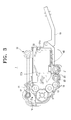
- FIG. 3 is a sectional view illustrating the developing apparatus 1 of FIG. 2 when no developer cartridge is mounted in the developing apparatus.
- the developing apparatus 1 may include a developing cartridge 10, to which the developer cartridge 50 may be removably received.
- the developing cartridge 10 may include a housing 11, an image carrier 12, a developing roller 13, a developer-storing portion 20, and a mounting recess 30.
- the housing 11 forms the external appearance of the developing cartridge 10, and may support therein the image carrier 12 and/or the developing roller 13.
- a folding handle 19 may be disposed at a side of the housing 11. The handle 19 may be used when the developing cartridge 10 is mounted to and separated from the image forming apparatus 100 (see FIG. 15 ).
- the image carrier 12 may be rotatably disposed inside the housing 11, and a portion of the image carrier 12 may be exposed to outside of the housing 11 through an opening formed at the housing 11.
- An image carrier-cleaning unit 16 to remove developer remaining on the image carrier 12 and a charging roller 17 to charge a surface of the image carrier 12 may also be disposed adjacent the image carrier 12.
- the image carrier 12 is provided as housed within the developing cartridge 10. Alternatively, however, the image carrier 12 may be provided separate from the developing cartridge 10.
- the developing roller 13 is rotatably disposed in the housing 11 adjacent the image carrier 12 for supplying the image carrier 12 with the developer from the developer-storing portion 20.
- a developer-supplying roller 14 may also be provided to convey developer to the developing roller 13 from the developer-storing portion 20.
- the developer-storing portion 20 is formed inside the housing 11 to store an amount of developer.
- One or more supply developer-conveying members 21, 22 may also be disposed in the developer-storing portion 20, for conveying and/or for circulating the developer stored in the developer-storing portion 20.
- two supply developer-conveying members 21 and 22 are disposed side by side in the developer-storing portion 20.
- any number in other arrangement of the supply developer conveying members may alternatively be provided.
- FIG. 4 is a partial perspective view illustrating the housing 11 of the developing cartridge 10 according to an embodiment with two supply developer-conveying members 21 and 22.
- the supply developer-conveying members 21 and 22 may be formed, e.g., substantially in a helical screw shape. Blades 23 with a predetermined width may be cut along the axial direction of the helical screw. The cut portions 24 of the supply developer-conveying member 21 and 22 remaining after the forming of the blades 23 may limit the pressure increase inside the developing cartridge 10.
- the cut portions 24 of the supply developer-conveying member 21 and 22 may exhibit a relatively lower pressure so that the developer in a high pressure region may move toward the cut portions 24 of the supply developer-conveying member 21 and 22, relieving the pressure inside the developing cartridge.
- the helical screw with partially cut blades 23 is used as the developer-conveying member 21 and 22, the amount of the developer inside the developer-storing portion 20 may be maintained substantially uniformly in the axial direction of the developer-conveying member 21 and 22.
- the supply developer-conveying member 21 and 22 may be formed substantially in a hollow helical screw shape similar to a discharge developer-conveying member 53 as described below.
- an inlet 20a is formed at the housing 11 above the developer-storing portion 20.
- the developer discharged from an outlet 50a of the developer cartridge 50 enters through the inlet 20a.
- the inlet 20a may be formed in various shapes. In this embodiment illustrated in FIG. 6 , the inlet 20a is formed as substantially a hexagon.
- a connecting member 40 may be disposed above the inlet 20a.
- the connecting member 40 allows the outlet 50a of the developer cartridge 50 to be in communication with the inlet 20a of the developing cartridge 10, thereby allowing the developer to move between the developer cartridge 50 and the developing cartridge 10.
- the connecting member 40 may be formed separately and disposed at the inlet 20a. In the embodiment illustrated in FIGS. 2 and 3 , the connecting member 40 is formed to extend and project from the inlet 20a of the housing 11.
- An inner section of the connecting member 40 is formed to correspond to a shape of any one of the outlet 50a of the developer cartridge 50 or the inlet 20a of the housing 11 of the developing cartridge 10. For example, when the sectional shape of the inlet 20a is formed as substantially a hexagon as illustrated in FIG. 6 , the inner sectional shape of the connecting member 40 may be formed in a hexagon corresponding to the sectional shape of the inlet 20a.
- the connecting member 40 may have a predetermined height H (see FIG. 7 ) so that when the developer cartridge 50 is mounted to the developing cartridge 10, the developer can flow back through the connecting member 40 according to the discharging pressure in the outlet 50a of the developer cartridge 50 and the entering pressure in the inlet 20a of the developing cartridge 10.
- the dimension of the maximum width W of the inlet 20a of the developing cartridge 10 may be larger than the dimension of the height H of the connecting member 40.
- the outlet 50a of the developer cartridge 50 may have the same shape as that of the inlet 20a of the developing cartridge 10 so that the height H of the connecting member 40 may also be smaller than the maximum width W of the outlet 50a of the developer cartridge 50.
- the area of the inner section A (a hatched portion in FIG. 6 ) of the connecting member 40 may be made to be at least ten times the height H of the connecting member 40. That is, the connecting member 40 may be formed to satisfy an inequality A ⁇ 10 x H.
- the units of the dimensions may be ignored, and only the numerical values may be considered.
- the inlet 20a of the developing cartridge 10 has a hexagonal shape with a maximum width W of approximate 12mm, a minimum width V of approximate 8mm, and a section area A of approximate 90 nim 2 .
- the height H of the connecting member 40 for this example may be approximate 2 mm to 5mm. Therefore the maximum width W of the inlet 20a of the developing cartridge 10 is larger than the height H of the connecting member 40.
- the section area A of the inlet 20a of the developing cartridge 10 is 90 and ten times the height H of the connecting member 40 is approximate 20 to 50. Accordingly, the above inequality is satisfied.
- the mounting recess 30 may be formed in a shape corresponding to the developer cartridge 50 in the housing 10 so that the developer cartridge 50 can be detachably mounted into the mounting recess 30.
- the mounting recess 30 may be formed to extend parallel to the developing roller 13.
- At least one mounting guiding groove 31a and 31b may be formed in the mounting recess 30 to guide the developer cartridge 50 when being mounted.
- the developer cartridge 50 may have at least one mounting guide 59a and 59b corresponding to the at least one mounting guiding groove 31a and 31b formed in the mounting recess 30.
- two mounting guiding grooves 31a and 31b are formed on opposite sides of the mounting recess 30 while the developer cartridge 50 has two mounting guides 59a and 59b corresponding to the two mounting guiding grooves 31a and 31b.
- a power-transmitting member (not illustrated) to transmit a power to the discharge developer-conveying member 21(22) or 53 (see FIGS. 4 and 9 ) of the developer cartridge 50 may disposed at the bottom of the mounting recess 30.
- the connecting member 40 may be disposed on the surface of the mounting recess 30 adjacent to the developer-storing portion 20.
- the developer cartridge 50 may be formed in generally a rectangular parallelepiped shape.
- a developer-receiving portion 51 in which a predetermined amount of developer may be stored is formed inside the developer cartridge 50.
- the discharge developer-conveying member 53 is rotatably disposed in the developer-receiving portion 51.
- a waste developer-receiving portion 52 may optionally be disposed at a side of the developer-receiving portion 51 parallel to the developer-receiving portion 51.
- the waste developer-receiving portion 52 may receive waste developer removed from the image carrier 12 by the image carrier-cleaning unit 16.
- the outlet 50a is formed on the bottom surface of the developer cartridge 50.
- the developer stored in the developer-receiving portion 51 is moved to the outlet 50a by the discharge developer-conveying member 53, and is discharged outside the developer cartridge 50 through the outlet 50a.
- the bottom surface of the developer-receiving portion 51 may be stepped as illustrated in FIG. 10 . That is, the bottom surface of the first portion 51a of the developer-receiving portion 51 close to the outlet 50a may be higher than the bottom surface of the second portion 51b of the developer-receiving portion 51 away from the outlet 50a, and in which the developer is generally stored.
- a pressure being applied to the outlet 50a by the developer stored in the developer-receiving portion 51 may be maintained at a lower level.
- the discharge developer-conveying member 53 includes a conveying portion 56 to convey the developer to the outlet 50a, and a backflow portion 57 through which the developer can move in a direction opposite to the direction in which the developer is conveyed by the conveying portion 56 when the pressure in the vicinity of the outlet 50a of the developer cartridge 50 increases.
- the discharge developer-conveying member 53 is formed in substantially a hollow helical screw shape. The helical blade of the screw corresponds to the conveying portion 56 that conveys the developer to the outlet 50a while the hollow portion of the screw corresponds to the backflow portion 57 through which the developer moves from the outlet 50a in the direction opposite to the discharging direction of the developer.
- the developer When there is more than a predetermined amount of developer in the developer-receiving portion 51 of the developer cartridge 50, the developer is moved toward the outlet 50a by an axial conveying force generated by the hollow helical screw 53 of FIG. 11 (see arrows F1 in FIG. 9 ). At this time, the hollow portion 57 of the helical screw 53 may exhibit a relatively lower pressure than the other portion. Therefore, when a developer pressure in the vicinity of the outlet 50a (that is, the discharging pressure) increases to over a certain value, although the helical screw 53 rotates, the developer may stop from moving in the direction F1, and may gather in the hollow portion 57 of the helical screw 53 having the relatively lower pressure.
- a developer pressure in the vicinity of the outlet 50a that is, the discharging pressure
- the developer that was gathered in the hollow portion 57 of the helical screw 53 may move along the hollow portion 57 in the direction opposite to the axial conveying force of the helical screw 53 (see arrow F3 in FIG. 9 ).
- the developer may continue to flow backward until the pressure in the vicinity of the outlet 50a becomes substantially the same as that of the hollow portion 57 of the helical screw 53.
- This process allows the decrease of the high pressure in the vicinity of the outlet 50a of the developer cartridge 50.
- the discharge developer-conveying member 53 may allow the developer pressure to be lowered.
- the discharge developer-conveying member 53 may include a small diameter portion 53a corresponding to the bottom surface of the first portion 51a of the developer-receiving portion 51, a large diameter portion 53b corresponding to the bottom surface of the second portion 51b of the developer-receiving portion 51, and a driving shaft 53c.
- a difference between the diameter D2 of the large diameter portion 53b and the diameter D1 of the small diameter portion 53a of the discharge developer-conveying member 53 may correspond to the height difference between the bottom surface of the first portion 51a and the bottom surface of the second portion 51b, that is, the height S1 of the stepped portion 54 of the developer-receiving portion 51.
- the driving shaft 53c may receive the power from the power-transmitting member (not illustrated) disposed in the mounting recess 30 of the developing cartridge 10.
- the large diameter portion 53b of the discharge developer-conveying member 53 may be formed so that each of the blades 56 of the screw has an increasing width as getting closer toward the small diameter portion 53a.
- the large diameter portion 53b of the discharge developer-conveying member 53 may be formed so that the width S2 of the blade 55 of the large diameter portion 53b nearby the small diameter portion 53a, that is, the blade 55 of the large diameter portion 53b nearby the stepped portion 54 of the developer-receiving portion 51, has the size larger than the size of the height S1 of the stepped portion 54 of the developer-receiving portion 51.
- the discharge developer-conveying member 53 can effectively convey the developer from the lower height developer-receiving portion 51 to the higher height outlet 50a.
- the large diameter portion 53b of the discharge developer-conveying member 53 may be formed so that only one blade 55 nearby the small diameter portion 53a has a width larger than those of the blades 56 in other portions.
- the width S2 of the blade 55 of the large diameter portion 53b nearby the small diameter portion 53a may have a size larger than the size of the height S1 of the stepped portion 54 of the developer-receiving portion 51.
- the large diameter portion 53b of the discharge developer-conveying member 51 may be formed to have the wider width blade 55 in approximately a half turn.
- the discharge developer-conveying member 53 is described as utilizing a hollow helical screw shape. However, this should not be considered as limiting.
- the discharge developer-conveying member 53 may be formed in various structures as long as the structure allows the developer to flow back from the outlet 50a.
- the discharge developer-conveying member 53 may be formed in a shape similar to the supply developer-conveying member 21 and 22 as described above.
- the developer-receiving portion 51 may be formed so that the width W1 of the first portion 51a, in which the outlet 50a is formed, may be narrower than the width W2 of the second portion 51b of the developer-receiving portion 51.
- the width W1 of the first portion 51a may be formed to be of the size corresponding to the small diameter portion 53a of the discharge developer-conveying member 53.
- FIG. 13 is a sectional view conceptually illustrating the developing apparatus 1 usable with an image forming apparatus according to the above described embodiments.
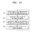
- FIG. 14 is a flowchart illustrating a developer supplying method of the developing apparatus 1 usable with an image forming apparatus according to an embodiment.
- FIGS. 13 and 14 an embodiment of the processes of supplying developer using the developing apparatus 1 will be described with reference to FIGS. 13 and 14 .
- the discharging pressure P1 When the developer pressure in the vicinity of the outlet 50a of the developer cartridge 50 is referred to the discharging pressure P1, and the developer pressure in the vicinity of the inlet 20a of the developing cartridge 10 is referred to the entering pressure P2, there may be a supplying mode, a stopping mode, and a back flowing mode inside the developing apparatus 1 according to the changes in the discharging pressure P1 and the entering pressure P2.
- the supplying mode represents a case in which the developer of the developer cartridge 50 moves to the developing cartridge 10 through the connecting member 40 (see arrows F1 and F2).
- the back flowing mode represents a case in which the developer of the developing cartridge 10 moves to the developer cartridge 50 through the connecting member 40 (see arrows F3 and F4).
- the stopping mode represents a case in which the developer does not move through the connecting member 40.
- the developer in the developer-storing portion 20 of the developing cartridge 10 is circulated in the direction indicated by the arrow F5, and is conveyed to the developing roller 13 by, e.g., the two supply developer-conveying members 21 and 22, to be consumed.
- the entering pressure P2 may decrease to a level lower than the discharging pressure P1. This represents the supplying mode, in which the developer of the developer cartridge 50 moves to the developing cartridge 10 in the direction indicated by the arrow F2 (Step 10).
- the pressure in the developing cartridge 10 may increase so that the entering pressure P2 becomes substantially the same as the discharging pressure P1.
- the stopping mode occurs so that the developer of the developer cartridge 50 does not move to the developing cartridge 10 through the connecting member 40 (Step 20).
- the back flowing mode may occur so that the developer of the developing cartridge 10 may move to the developer cartridge 50 through the connecting member 40 as arrow F4 (step S30).
- the entering pressure P2 gradually becomes lower.
- the entering pressure P2 of the developing cartridge 10 may become substantially the same as the discharging pressure P1 of the developer cartridge 50, entering once again the stopping mode (step S40).
- the entering pressure P2 eventually becomes lower than the discharging pressure P1. So the developer in the connecting member 40 moves again to the developing cartridge 10.
- the developing apparatus 1 may repeat the above processes of the supplying mode -> the stopping mode -> the back flowing mode -> stopping mode -> supplying mode, and so on, thereby constantly maintaining the amount of the developer in the developer-storing portion 20 of the developing cartridge 10.
- the discharge developer-conveying member 53 of the developer cartridge 50 is formed in the hollow helical screw shape, in the back flowing mode in which the developer of the developing cartridge 10 flows back to the developer cartridge 50 through the connecting member 40, the developer entering the developer cartridge 50 moves along the hollow portion 57 of the discharge developer-conveying member 53 in the direction opposite to the outlet 50a. As a result, the discharging pressure P1 in the vicinity of the outlet 50a may decrease.
- the outlet 50a of the developer cartridge 50 may be located above the connecting member 40.
- the developer of the developer cartridge 50 is supplied to the developing cartridge 10 through the outlet 50a. That is, when the developing cartridge 10 having the developer cartridge 50 mounted in the mounting hole recess thereof is mounted in the image forming apparatus 100, the discharge developer-conveying member 53 of the developer cartridge 50 receives power from the image forming apparatus 100, and may rotate. When the discharge developer-conveying member 53 rotates, the developer stored in the developer-receiving portion 51 of the developer cartridge 50 moves to the outlet 50a, and is discharged to the connecting member 40.
- the developer discharged to the connecting member 40 enters the developer-storing portion 20 of the developing cartridge 10 through the inlet 20a.
- the developer entering the developer-storing portion 20 is conveyed by, e.g., the two supply developer-conveying members 21 and 22, and is supplied to the developer supplying roller 14.
- the developer supplying roller 14 supplies the developer to the developing roller 13.
- the developer supplied onto the surface of the developing roller 13 moves to the image carrier 12, and develops the electrostatic latent images formed on the image carrier 12 into developer images.
- the entering pressure P2 in the inlet 20a of the developing cartridge 10 becomes lower.
- the developer of the developer cartridge 50 is supplied to the developing cartridge 10.
- the developer of the developer cartridge 50 is supplied so that the entering pressure P2 of the developing cartridge 10 becomes higher, the developer of the developer cartridge 50 is not supplied or the developer of the developing cartridge 10 flows back the developer cartridge 50. Therefore, the developer in the developer-storing portion 20 of the developing cartridge 10 is constantly maintained.
- the developer moving statuses according to changes of the entering pressure P2 and the discharging pressure P1 are described above. Therefore, detailed descriptions thereof are not repeated.
- FIG. 15 is a sectional view schematically illustrating an image forming apparatus 100 using a developing apparatus 1 according to an embodiment of the present invention.
- the image forming apparatus 100 may include a case 110, a printing medium feeding unit 120, an exposure unit 130, the developing apparatus 1, a transferring roller 140, a fixing unit 150, and a discharging roller 160.
- the case 110 forms an appearance of the image forming apparatus 100, and may support the printing medium feeding unit 120, the exposure unit 130, the developing apparatus 1, the transferring roller 140, the fixing unit 150, and the discharging roller 160.
- the printing medium feeding unit 120 stores printing media P, and picks up the printing media P one by one to feed the printing medium P to the developing apparatus 1. To that end, a pickup roller 121 may be disposed at the leading end of the printing medium feeding unit 120.
- the exposure unit 130 emits a laser beam corresponding to print data to form electrostatic latent images on the image carrier 12 of the developing apparatus 1.
- the developing apparatus 1 stores a quantity of developer, and develops the electrostatic latent images formed on the image carrier 12 into developer images.
- the developing apparatus 1 is detachably disposed in the case 110. When the developing apparatus 1 is disposed in the case 110, power is transmitted from a driving apparatus (not illustrated) disposed inside the case 110 so that the image carrier 12, the developing roller 13, the supply developer-conveying members 21 and 22, and/or the discharge developer-conveying member 53 rotate.
- a driving apparatus not illustrated
- the transfer roller 140 causes the developer images formed on the image carrier 12 to be transferred onto the printing medium P.
- the fixing unit 150 causes the developer images transferred onto the printing medium P to be fixed onto the printing medium P.
- the discharging roller 160 discharges the printing medium P having the developer images fixed thereon outside the image forming apparatus 100.
- the image forming apparatus 100 controls the exposure unit 130 to emit a laser beam corresponding to printing data and form electrostatic latent images corresponding to the printing data on the image carrier 12 of the developing apparatus 1. Then, the developing roller 13 of the developing apparatus 1 supplies developer to the image carrier 12, thereby developing the electrostatic latent images into developer images.
- the developer in the developer-storing portion 20 of the developing cartridge 10 is constantly maintained.
- the image forming apparatus 100 also controls the printing medium feeding unit 120 to pick up and feed a printing medium P between the transfer roller 140 and the image carrier 12. Then, the developer images are transferred from the image carrier 12 to the printing medium P.
- the printing medium P having the developer images transferred thereon passes through the fixing unit 150 and the discharging roller 160, thereby being discharged outside the image forming apparatus 100.
- the developing apparatus 1 usable with the image forming apparatus according to the above-described embodiments, when the developer runs out, only the developer cartridge 50 can be required to be replaced with a new developer cartridge.
- the developing apparatus 1 usable with the image forming apparatus of the embodiments herein described, during supplying the developer from the developer cartridge 50 to the developing cartridge 10 when the pressure in the developing cartridge 10 and the connecting member 40 is increased over a predetermined pressure, although the supply developer-conveying member 53 continues to rotate for supplying the developer, the developer does not move to the developing cartridge 10 and/or the developer may flow back from the developing cartridge 10 to the developer cartridge 50 so that the amount of developer in the developing cartridge 10 is continuously maintained.
Landscapes
- Physics & Mathematics (AREA)
- General Physics & Mathematics (AREA)
- Dry Development In Electrophotography (AREA)
Applications Claiming Priority (1)
| Application Number | Priority Date | Filing Date | Title |
|---|---|---|---|
| KR1020080016455A KR100899350B1 (ko) | 2008-02-22 | 2008-02-22 | 현상장치, 이를 구비한 화상형성장치, 및 현상장치의토너공급방법 |
Publications (3)
| Publication Number | Publication Date |
|---|---|
| EP2093625A2 true EP2093625A2 (fr) | 2009-08-26 |
| EP2093625A3 EP2093625A3 (fr) | 2010-02-24 |
| EP2093625B1 EP2093625B1 (fr) | 2015-08-12 |
Family
ID=40627371
Family Applications (1)
| Application Number | Title | Priority Date | Filing Date |
|---|---|---|---|
| EP09150144.5A Not-in-force EP2093625B1 (fr) | 2008-02-22 | 2009-01-07 | Appareil de développement et cartouche de développateur |
Country Status (6)
| Country | Link |
|---|---|
| US (1) | US8213838B2 (fr) |
| EP (1) | EP2093625B1 (fr) |
| KR (1) | KR100899350B1 (fr) |
| CN (1) | CN101515143B (fr) |
| BR (1) | BRPI0805359B1 (fr) |
| RU (1) | RU2405180C2 (fr) |
Cited By (3)
| Publication number | Priority date | Publication date | Assignee | Title |
|---|---|---|---|---|
| EP2853954A1 (fr) * | 2013-09-18 | 2015-04-01 | Kyocera Document Solutions Inc. | Dispositif de développement et appareil de formation d'image associé |
| EP2667261A3 (fr) * | 2012-05-25 | 2017-08-30 | Kyocera Document Solutions Inc. | Dispositif de transport |
| EP2687914B1 (fr) * | 2012-07-19 | 2018-01-17 | KYOCERA Document Solutions Inc. | Dispositif de transport de révélateur et dispositif de révélateur et appareil de formation d'images équipé de celui-ci |
Families Citing this family (8)
| Publication number | Priority date | Publication date | Assignee | Title |
|---|---|---|---|---|
| JP5393765B2 (ja) * | 2011-12-19 | 2014-01-22 | 京セラドキュメントソリューションズ株式会社 | 現像装置及びそれを備えた画像形成装置 |
| JP5589027B2 (ja) * | 2012-05-25 | 2014-09-10 | 京セラドキュメントソリューションズ株式会社 | 現像剤搬送装置、およびこれを備える現像装置、画像形成装置 |
| JP5629725B2 (ja) * | 2012-05-25 | 2014-11-26 | 京セラドキュメントソリューションズ株式会社 | 現像装置、およびこれを備える画像形成装置 |
| JP5629726B2 (ja) * | 2012-05-25 | 2014-11-26 | 京セラドキュメントソリューションズ株式会社 | 現像装置、およびこれを備える画像形成装置 |
| JP5661065B2 (ja) * | 2012-05-25 | 2015-01-28 | 京セラドキュメントソリューションズ株式会社 | 現像剤搬送装置、およびこれを備える現像装置、画像形成装置 |
| EP3093716B1 (fr) | 2015-05-15 | 2020-09-30 | Canon Kabushiki Kaisha | Dispositif de nettoyage, cartouche de procédé et appareil de formation d'image |
| JP2017083559A (ja) * | 2015-10-26 | 2017-05-18 | キヤノンファインテック株式会社 | 現像装置、プロセスカートリッジ及び画像形成装置 |
| JP6699212B2 (ja) * | 2016-02-10 | 2020-05-27 | 富士ゼロックス株式会社 | 現像装置および画像形成装置 |
Family Cites Families (47)
| Publication number | Priority date | Publication date | Assignee | Title |
|---|---|---|---|---|
| JPS60238873A (ja) | 1984-05-11 | 1985-11-27 | Fuji Xerox Co Ltd | トナ−補給装置 |
| US4974020A (en) | 1986-09-30 | 1990-11-27 | Mita Industrial Co. | Removable developing units for a copying machine and display for indicating the useful life of the machine |
| JPS6491164A (en) | 1987-10-02 | 1989-04-10 | Ricoh Kk | Developing device |
| US4967234A (en) | 1987-11-10 | 1990-10-30 | Ricoh Company, Ltd. | Image forming apparatus |
| KR910000435Y1 (ko) * | 1987-12-31 | 1991-01-21 | 주식회사 금성사 | 복사기의 토너 공급장치 |
| JP2965041B2 (ja) | 1988-11-08 | 1999-10-18 | 株式会社リコー | 画像形成装置 |
| US5068691B1 (en) | 1989-06-01 | 1995-01-24 | Fujitsu Ltd | Developing device with a controllable pressure release for the developing roller |
| US5493366A (en) | 1990-09-07 | 1996-02-20 | Konica Corporation | Image forming apparatus |
| JP3060725B2 (ja) | 1992-06-30 | 2000-07-10 | 富士通株式会社 | 現像剤カ−トリッジ及びこれを用いた画像形成装置 |
| JP3244992B2 (ja) | 1994-03-15 | 2002-01-07 | キヤノン株式会社 | 電子写真画像形成装置 |
| JP3263533B2 (ja) | 1994-05-17 | 2002-03-04 | ブラザー工業株式会社 | トナー残量検出装置及びそのトナー収納装置 |
| JP3384914B2 (ja) | 1994-10-04 | 2003-03-10 | 株式会社リコー | 現像装置 |
| JPH0922177A (ja) | 1995-07-04 | 1997-01-21 | Canon Inc | トナーカートリッジ、プロセスカートリッジ、トナーホッパー及び画像形成装置 |
| JPH10142910A (ja) | 1996-11-08 | 1998-05-29 | Katsuragawa Electric Co Ltd | トナー供給方式 |
| US5797073A (en) | 1997-03-13 | 1998-08-18 | Xerox Corporation | Toner container with biased closure |
| JP3037194B2 (ja) | 1997-04-25 | 2000-04-24 | 新潟日本電気株式会社 | プロセスカートリッジへのトナーの供給方法及び画像形成装置用プロセスカートリッジ |
| US6968139B2 (en) | 1997-06-19 | 2005-11-22 | Canon Kabushiki Kaisha | Toner supply container and electrophotographic image forming apparatus |
| JPH1124513A (ja) | 1997-06-27 | 1999-01-29 | Canon Inc | トナー補給装置及び電子写真画像形成装置 |
| KR100290603B1 (ko) * | 1997-08-05 | 2001-06-01 | 윤종용 | 화상형성장치의현상롤러 |
| JP3408166B2 (ja) | 1997-09-30 | 2003-05-19 | キヤノン株式会社 | トナー供給容器及び電子写真画像形成装置 |
| JP3321728B2 (ja) | 1997-11-06 | 2002-09-09 | 京セラミタ株式会社 | 画像形成機のトナー補給装置およびこれに用いるトナーカートリッジ |
| JP3721749B2 (ja) | 1997-11-12 | 2005-11-30 | コニカミノルタビジネステクノロジーズ株式会社 | 画像形成装置のユニットおよびそのユニットを用いる画像形成装置および画像形成装置のユニット検出装置および画像形成装置のユニット検出方法 |
| JP3604919B2 (ja) | 1998-08-31 | 2004-12-22 | キヤノン株式会社 | カラー電子写真画像形成装置及び現像カートリッジ |
| JP3627528B2 (ja) | 1998-09-02 | 2005-03-09 | 富士ゼロックス株式会社 | 現像装置 |
| JP4054521B2 (ja) | 1999-11-29 | 2008-02-27 | キヤノン株式会社 | 現像剤補給カートリッジ及び現像剤補給システム |
| JP2001255727A (ja) * | 2000-03-09 | 2001-09-21 | Oki Data Corp | トナーカートリッジ及び該トナーカートリッジが装着される印刷装置。 |
| DE10043016B4 (de) | 2000-09-01 | 2006-11-23 | Walter Ag | Bohrnutenfräser |
| KR100362390B1 (ko) | 2000-12-29 | 2002-11-23 | 삼성전자 주식회사 | 화상형성장치의 현상기-토너 카트리지 조립체 |
| EP1233311B1 (fr) * | 2001-02-19 | 2012-08-29 | Canon Kabushiki Kaisha | Récipient d'alimentation en toner |
| US6751428B2 (en) | 2001-09-13 | 2004-06-15 | Brother Kogyo Kabushiki Kaisha | Image forming device and detachably loaded process unit |
| JP3534104B2 (ja) | 2001-12-20 | 2004-06-07 | 富士ゼロックス株式会社 | 画像形成装置及びこれに用いられるプロセスカートリッジ、現像装置 |
| JP3982346B2 (ja) | 2002-06-28 | 2007-09-26 | コニカミノルタビジネステクノロジーズ株式会社 | 画像形成装置のトナーカートリッジ |
| JP2004170955A (ja) | 2002-11-08 | 2004-06-17 | Canon Inc | 画像形成装置及びカートリッジ、画像形成システム、カートリッジ用メモリ媒体 |
| JP4242667B2 (ja) | 2003-02-28 | 2009-03-25 | 株式会社東芝 | トナーカートリッジ及び画像形成装置 |
| US7076179B2 (en) | 2003-03-20 | 2006-07-11 | Seiko Epson Corporation | Image forming apparatus and a storage controlling method for information on an improper detachment of developer cartridge to be written in a cartridge storage means |
| JP4225135B2 (ja) * | 2003-06-26 | 2009-02-18 | コニカミノルタビジネステクノロジーズ株式会社 | 現像装置および画像形成装置 |
| JP3673793B2 (ja) | 2003-08-29 | 2005-07-20 | キヤノン株式会社 | プロセスカートリッジ、プロセスカートリッジの装着機構及び電子写真画像形成装置 |
| JP4378221B2 (ja) | 2003-10-08 | 2009-12-02 | キヤノン株式会社 | プロセスカートリッジ及び電子写真画像形成装置 |
| KR100553897B1 (ko) | 2003-10-31 | 2006-02-24 | 삼성전자주식회사 | 메모리를 이용한 화상형성장치의 소모품 관리 장치 |
| JP4525167B2 (ja) | 2004-05-14 | 2010-08-18 | 富士ゼロックス株式会社 | 現像剤回収機構及び画像形成装置 |
| JP2005338329A (ja) | 2004-05-26 | 2005-12-08 | Fuji Xerox Co Ltd | プロセスカートリッジ及び画像形成装置 |
| KR20060034168A (ko) | 2004-10-18 | 2006-04-21 | 삼성전자주식회사 | 화상형성기기의 상형성장치 |
| KR101349988B1 (ko) | 2005-03-04 | 2014-01-13 | 캐논 가부시끼가이샤 | 현상제 공급 용기 및 현상제 공급 시스템 |
| KR100677595B1 (ko) * | 2005-06-10 | 2007-02-02 | 삼성전자주식회사 | 현상기 및 이를 채용한 칼라화상형성장치 |
| JP4315933B2 (ja) | 2005-07-21 | 2009-08-19 | 株式会社沖データ | 現像剤カートリッジ、現像装置、及び画像形成装置 |
| JP4681489B2 (ja) * | 2006-03-31 | 2011-05-11 | 株式会社沖データ | トナーカートリッジ、現像装置、及び画像形成装置 |
| JP4710760B2 (ja) | 2006-08-29 | 2011-06-29 | 富士ゼロックス株式会社 | 現像剤搬送装置および画像形成装置 |
-
2008
- 2008-02-22 KR KR1020080016455A patent/KR100899350B1/ko not_active Expired - Fee Related
- 2008-08-14 US US12/191,682 patent/US8213838B2/en not_active Expired - Fee Related
- 2008-09-05 CN CN2008102153171A patent/CN101515143B/zh not_active Expired - Fee Related
- 2008-12-09 RU RU2008148667/28A patent/RU2405180C2/ru active
- 2008-12-10 BR BRPI0805359A patent/BRPI0805359B1/pt not_active IP Right Cessation
-
2009
- 2009-01-07 EP EP09150144.5A patent/EP2093625B1/fr not_active Not-in-force
Non-Patent Citations (1)
| Title |
|---|
| None |
Cited By (3)
| Publication number | Priority date | Publication date | Assignee | Title |
|---|---|---|---|---|
| EP2667261A3 (fr) * | 2012-05-25 | 2017-08-30 | Kyocera Document Solutions Inc. | Dispositif de transport |
| EP2687914B1 (fr) * | 2012-07-19 | 2018-01-17 | KYOCERA Document Solutions Inc. | Dispositif de transport de révélateur et dispositif de révélateur et appareil de formation d'images équipé de celui-ci |
| EP2853954A1 (fr) * | 2013-09-18 | 2015-04-01 | Kyocera Document Solutions Inc. | Dispositif de développement et appareil de formation d'image associé |
Also Published As
| Publication number | Publication date |
|---|---|
| BRPI0805359B1 (pt) | 2019-10-22 |
| CN101515143B (zh) | 2013-06-19 |
| KR100899350B1 (ko) | 2009-05-27 |
| EP2093625A3 (fr) | 2010-02-24 |
| US20090214268A1 (en) | 2009-08-27 |
| BRPI0805359A2 (pt) | 2009-10-06 |
| RU2008148667A (ru) | 2010-07-20 |
| EP2093625B1 (fr) | 2015-08-12 |
| US8213838B2 (en) | 2012-07-03 |
| RU2405180C2 (ru) | 2010-11-27 |
| CN101515143A (zh) | 2009-08-26 |
Similar Documents
| Publication | Publication Date | Title |
|---|---|---|
| US8213838B2 (en) | Developing apparatus, image forming apparatus having the same, and developer supplying method for a developing apparatus | |
| JP5660312B2 (ja) | 現像剤搬送装置、現像剤収容器、現像装置、プロセスユニット及び画像形成装置 | |
| JP4715263B2 (ja) | クリーニング装置及びこれを用いたプロセスカートリッジ並びに画像形成装置 | |
| US8666288B2 (en) | Developing device and image forming apparatus | |
| JP2006251440A (ja) | 現像装置、プロセスカートリッジ、及び画像形成装置 | |
| US8073368B2 (en) | Development device and image forming apparatus | |
| JP2010020227A (ja) | 現像剤補給装置、および電子写真画像形成装置 | |
| US20110280623A1 (en) | Toner cartridge with waste toner storage and image forming apparatus having the same | |
| US5867756A (en) | Developing device with an auger roller for providing a fresh and consistent stream of developer in an image forming apparatus | |
| EP1333336B1 (fr) | Méthode d'alimentation en toner et unité utilisée dans un appareil de formation d'images | |
| CN103765321A (zh) | 墨粉容器 | |
| US8989634B2 (en) | Developer case that suppresses clogging due to developer, developer replenishment unit having the same, and image forming apparatus having the same | |
| JP2017083559A (ja) | 現像装置、プロセスカートリッジ及び画像形成装置 | |
| US20080199225A1 (en) | Toner conveying apparatus | |
| JP2006276810A (ja) | 粉体搬送部材及びこれを用いた粉体処理装置 | |
| JP2006267922A (ja) | プロセスカートリッジ及びこれを用いた画像形成装置 | |
| JP2021047340A (ja) | 画像形成装置 | |
| JP2005091715A (ja) | トナー補給装置及び画像形成装置 | |
| JP4742640B2 (ja) | プロセスカートリッジ及び画像形成装置 | |
| JP2006215331A (ja) | 現像装置及び該現像装置を用いる画像形成装置 | |
| JP4308631B2 (ja) | 現像装置 | |
| JP4952853B2 (ja) | クリーニング装置及びこれを用いたプロセスカートリッジ並びに画像形成装置 | |
| KR101153201B1 (ko) | 화상형성장치의 현상장치 | |
| JP4527443B2 (ja) | 現像装置 | |
| US8406679B2 (en) | Image forming unit and image forming apparatus |
Legal Events
| Date | Code | Title | Description |
|---|---|---|---|
| PUAI | Public reference made under article 153(3) epc to a published international application that has entered the european phase |
Free format text: ORIGINAL CODE: 0009012 |
|
| 17P | Request for examination filed |
Effective date: 20090107 |
|
| AK | Designated contracting states |
Kind code of ref document: A2 Designated state(s): AT BE BG CH CY CZ DE DK EE ES FI FR GB GR HR HU IE IS IT LI LT LU LV MC MK MT NL NO PL PT RO SE SI SK TR |
|
| AX | Request for extension of the european patent |
Extension state: AL BA RS |
|
| RTI1 | Title (correction) |
Free format text: DEVELOPING APPARATUS, IMAGE FORMING APPARATUS HAVING THE SAME, AND DEVELOPER SUPPLYING METHOD FOR A DEVELOPING APPARATUS |
|
| PUAL | Search report despatched |
Free format text: ORIGINAL CODE: 0009013 |
|
| AK | Designated contracting states |
Kind code of ref document: A3 Designated state(s): AT BE BG CH CY CZ DE DK EE ES FI FR GB GR HR HU IE IS IT LI LT LU LV MC MK MT NL NO PL PT RO SE SI SK TR |
|
| AX | Request for extension of the european patent |
Extension state: AL BA RS |
|
| AKX | Designation fees paid |
Designated state(s): AT BE BG CH CY CZ DE DK EE ES FI FR GB GR HR HU IE IS IT LI LT LU LV MC MK MT NL NO PL PT RO SE SI SK TR |
|
| 17Q | First examination report despatched |
Effective date: 20101207 |
|
| RAP1 | Party data changed (applicant data changed or rights of an application transferred) |
Owner name: SAMSUNG ELECTRONICS CO., LTD. |
|
| GRAP | Despatch of communication of intention to grant a patent |
Free format text: ORIGINAL CODE: EPIDOSNIGR1 |
|
| INTG | Intention to grant announced |
Effective date: 20150305 |
|
| GRAS | Grant fee paid |
Free format text: ORIGINAL CODE: EPIDOSNIGR3 |
|
| GRAA | (expected) grant |
Free format text: ORIGINAL CODE: 0009210 |
|
| AK | Designated contracting states |
Kind code of ref document: B1 Designated state(s): AT BE BG CH CY CZ DE DK EE ES FI FR GB GR HR HU IE IS IT LI LT LU LV MC MK MT NL NO PL PT RO SE SI SK TR |
|
| REG | Reference to a national code |
Ref country code: GB Ref legal event code: FG4D |
|
| REG | Reference to a national code |
Ref country code: CH Ref legal event code: EP |
|
| REG | Reference to a national code |
Ref country code: AT Ref legal event code: REF Ref document number: 742675 Country of ref document: AT Kind code of ref document: T Effective date: 20150815 |
|
| REG | Reference to a national code |
Ref country code: IE Ref legal event code: FG4D |
|
| REG | Reference to a national code |
Ref country code: DE Ref legal event code: R096 Ref document number: 602009032762 Country of ref document: DE |
|
| REG | Reference to a national code |
Ref country code: NL Ref legal event code: FP |
|
| REG | Reference to a national code |
Ref country code: LT Ref legal event code: MG4D |
|
| REG | Reference to a national code |
Ref country code: AT Ref legal event code: MK05 Ref document number: 742675 Country of ref document: AT Kind code of ref document: T Effective date: 20150812 |
|
| PG25 | Lapsed in a contracting state [announced via postgrant information from national office to epo] |
Ref country code: NO Free format text: LAPSE BECAUSE OF FAILURE TO SUBMIT A TRANSLATION OF THE DESCRIPTION OR TO PAY THE FEE WITHIN THE PRESCRIBED TIME-LIMIT Effective date: 20151112 Ref country code: FI Free format text: LAPSE BECAUSE OF FAILURE TO SUBMIT A TRANSLATION OF THE DESCRIPTION OR TO PAY THE FEE WITHIN THE PRESCRIBED TIME-LIMIT Effective date: 20150812 Ref country code: LV Free format text: LAPSE BECAUSE OF FAILURE TO SUBMIT A TRANSLATION OF THE DESCRIPTION OR TO PAY THE FEE WITHIN THE PRESCRIBED TIME-LIMIT Effective date: 20150812 Ref country code: LT Free format text: LAPSE BECAUSE OF FAILURE TO SUBMIT A TRANSLATION OF THE DESCRIPTION OR TO PAY THE FEE WITHIN THE PRESCRIBED TIME-LIMIT Effective date: 20150812 Ref country code: GR Free format text: LAPSE BECAUSE OF FAILURE TO SUBMIT A TRANSLATION OF THE DESCRIPTION OR TO PAY THE FEE WITHIN THE PRESCRIBED TIME-LIMIT Effective date: 20151113 |
|
| PG25 | Lapsed in a contracting state [announced via postgrant information from national office to epo] |
Ref country code: ES Free format text: LAPSE BECAUSE OF FAILURE TO SUBMIT A TRANSLATION OF THE DESCRIPTION OR TO PAY THE FEE WITHIN THE PRESCRIBED TIME-LIMIT Effective date: 20150812 Ref country code: AT Free format text: LAPSE BECAUSE OF FAILURE TO SUBMIT A TRANSLATION OF THE DESCRIPTION OR TO PAY THE FEE WITHIN THE PRESCRIBED TIME-LIMIT Effective date: 20150812 Ref country code: PL Free format text: LAPSE BECAUSE OF FAILURE TO SUBMIT A TRANSLATION OF THE DESCRIPTION OR TO PAY THE FEE WITHIN THE PRESCRIBED TIME-LIMIT Effective date: 20150812 Ref country code: SE Free format text: LAPSE BECAUSE OF FAILURE TO SUBMIT A TRANSLATION OF THE DESCRIPTION OR TO PAY THE FEE WITHIN THE PRESCRIBED TIME-LIMIT Effective date: 20150812 Ref country code: HR Free format text: LAPSE BECAUSE OF FAILURE TO SUBMIT A TRANSLATION OF THE DESCRIPTION OR TO PAY THE FEE WITHIN THE PRESCRIBED TIME-LIMIT Effective date: 20150812 Ref country code: PT Free format text: LAPSE BECAUSE OF FAILURE TO SUBMIT A TRANSLATION OF THE DESCRIPTION OR TO PAY THE FEE WITHIN THE PRESCRIBED TIME-LIMIT Effective date: 20151214 Ref country code: IS Free format text: LAPSE BECAUSE OF FAILURE TO SUBMIT A TRANSLATION OF THE DESCRIPTION OR TO PAY THE FEE WITHIN THE PRESCRIBED TIME-LIMIT Effective date: 20151212 |
|
| PG25 | Lapsed in a contracting state [announced via postgrant information from national office to epo] |
Ref country code: DK Free format text: LAPSE BECAUSE OF FAILURE TO SUBMIT A TRANSLATION OF THE DESCRIPTION OR TO PAY THE FEE WITHIN THE PRESCRIBED TIME-LIMIT Effective date: 20150812 Ref country code: SK Free format text: LAPSE BECAUSE OF FAILURE TO SUBMIT A TRANSLATION OF THE DESCRIPTION OR TO PAY THE FEE WITHIN THE PRESCRIBED TIME-LIMIT Effective date: 20150812 Ref country code: EE Free format text: LAPSE BECAUSE OF FAILURE TO SUBMIT A TRANSLATION OF THE DESCRIPTION OR TO PAY THE FEE WITHIN THE PRESCRIBED TIME-LIMIT Effective date: 20150812 Ref country code: CZ Free format text: LAPSE BECAUSE OF FAILURE TO SUBMIT A TRANSLATION OF THE DESCRIPTION OR TO PAY THE FEE WITHIN THE PRESCRIBED TIME-LIMIT Effective date: 20150812 |
|
| REG | Reference to a national code |
Ref country code: DE Ref legal event code: R097 Ref document number: 602009032762 Country of ref document: DE |
|
| PG25 | Lapsed in a contracting state [announced via postgrant information from national office to epo] |
Ref country code: RO Free format text: LAPSE BECAUSE OF FAILURE TO SUBMIT A TRANSLATION OF THE DESCRIPTION OR TO PAY THE FEE WITHIN THE PRESCRIBED TIME-LIMIT Effective date: 20150812 Ref country code: BE Free format text: LAPSE BECAUSE OF NON-PAYMENT OF DUE FEES Effective date: 20160131 |
|
| PLBE | No opposition filed within time limit |
Free format text: ORIGINAL CODE: 0009261 |
|
| STAA | Information on the status of an ep patent application or granted ep patent |
Free format text: STATUS: NO OPPOSITION FILED WITHIN TIME LIMIT |
|
| 26N | No opposition filed |
Effective date: 20160513 |
|
| PG25 | Lapsed in a contracting state [announced via postgrant information from national office to epo] |
Ref country code: LU Free format text: LAPSE BECAUSE OF FAILURE TO SUBMIT A TRANSLATION OF THE DESCRIPTION OR TO PAY THE FEE WITHIN THE PRESCRIBED TIME-LIMIT Effective date: 20160107 Ref country code: SI Free format text: LAPSE BECAUSE OF FAILURE TO SUBMIT A TRANSLATION OF THE DESCRIPTION OR TO PAY THE FEE WITHIN THE PRESCRIBED TIME-LIMIT Effective date: 20150812 |
|
| REG | Reference to a national code |
Ref country code: CH Ref legal event code: PL |
|
| PG25 | Lapsed in a contracting state [announced via postgrant information from national office to epo] |
Ref country code: MC Free format text: LAPSE BECAUSE OF FAILURE TO SUBMIT A TRANSLATION OF THE DESCRIPTION OR TO PAY THE FEE WITHIN THE PRESCRIBED TIME-LIMIT Effective date: 20150812 |
|
| REG | Reference to a national code |
Ref country code: FR Ref legal event code: ST Effective date: 20160930 |
|
| PG25 | Lapsed in a contracting state [announced via postgrant information from national office to epo] |
Ref country code: LI Free format text: LAPSE BECAUSE OF NON-PAYMENT OF DUE FEES Effective date: 20160131 Ref country code: CH Free format text: LAPSE BECAUSE OF NON-PAYMENT OF DUE FEES Effective date: 20160131 |
|
| REG | Reference to a national code |
Ref country code: IE Ref legal event code: MM4A |
|
| PG25 | Lapsed in a contracting state [announced via postgrant information from national office to epo] |
Ref country code: FR Free format text: LAPSE BECAUSE OF NON-PAYMENT OF DUE FEES Effective date: 20160201 |
|
| PG25 | Lapsed in a contracting state [announced via postgrant information from national office to epo] |
Ref country code: BE Free format text: LAPSE BECAUSE OF FAILURE TO SUBMIT A TRANSLATION OF THE DESCRIPTION OR TO PAY THE FEE WITHIN THE PRESCRIBED TIME-LIMIT Effective date: 20150812 |
|
| PG25 | Lapsed in a contracting state [announced via postgrant information from national office to epo] |
Ref country code: IE Free format text: LAPSE BECAUSE OF NON-PAYMENT OF DUE FEES Effective date: 20160107 |
|
| REG | Reference to a national code |
Ref country code: NL Ref legal event code: PD Owner name: S-PRINTING SOLUTION CO., LTD.; KO Free format text: DETAILS ASSIGNMENT: CHANGE OF OWNER(S), ASSIGNMENT; FORMER OWNER NAME: SAMSUNG ELECTRONICS CO., LTD. Effective date: 20170221 |
|
| REG | Reference to a national code |
Ref country code: GB Ref legal event code: 732E Free format text: REGISTERED BETWEEN 20170406 AND 20170412 |
|
| REG | Reference to a national code |
Ref country code: DE Ref legal event code: R082 Ref document number: 602009032762 Country of ref document: DE Ref country code: DE Ref legal event code: R082 Ref document number: 602009032762 Country of ref document: DE Representative=s name: HOEFER & PARTNER PATENTANWAELTE MBB, DE Ref country code: DE Ref legal event code: R081 Ref document number: 602009032762 Country of ref document: DE Owner name: HP PRINTING KOREA CO., LTD., SUWON-SI, KR Free format text: FORMER OWNER: SAMSUNG ELECTRONICS CO., LTD., SUWON-SI, GYEONGGI-DO, KR Ref country code: DE Ref legal event code: R081 Ref document number: 602009032762 Country of ref document: DE Owner name: HEWLETT-PACKARD DEVELOPMENT COMPANY, L.P., SPR, US Free format text: FORMER OWNER: SAMSUNG ELECTRONICS CO., LTD., SUWON-SI, GYEONGGI-DO, KR Ref country code: DE Ref legal event code: R081 Ref document number: 602009032762 Country of ref document: DE Owner name: S-PRINTING SOLUTION CO., LTD., SUWON-SI, KR Free format text: FORMER OWNER: SAMSUNG ELECTRONICS CO., LTD., SUWON-SI, GYEONGGI-DO, KR |
|
| PG25 | Lapsed in a contracting state [announced via postgrant information from national office to epo] |
Ref country code: MT Free format text: LAPSE BECAUSE OF FAILURE TO SUBMIT A TRANSLATION OF THE DESCRIPTION OR TO PAY THE FEE WITHIN THE PRESCRIBED TIME-LIMIT Effective date: 20150812 |
|
| PG25 | Lapsed in a contracting state [announced via postgrant information from national office to epo] |
Ref country code: HU Free format text: LAPSE BECAUSE OF FAILURE TO SUBMIT A TRANSLATION OF THE DESCRIPTION OR TO PAY THE FEE WITHIN THE PRESCRIBED TIME-LIMIT; INVALID AB INITIO Effective date: 20090107 Ref country code: CY Free format text: LAPSE BECAUSE OF FAILURE TO SUBMIT A TRANSLATION OF THE DESCRIPTION OR TO PAY THE FEE WITHIN THE PRESCRIBED TIME-LIMIT Effective date: 20150812 |
|
| PG25 | Lapsed in a contracting state [announced via postgrant information from national office to epo] |
Ref country code: TR Free format text: LAPSE BECAUSE OF FAILURE TO SUBMIT A TRANSLATION OF THE DESCRIPTION OR TO PAY THE FEE WITHIN THE PRESCRIBED TIME-LIMIT Effective date: 20150812 Ref country code: MT Free format text: LAPSE BECAUSE OF FAILURE TO SUBMIT A TRANSLATION OF THE DESCRIPTION OR TO PAY THE FEE WITHIN THE PRESCRIBED TIME-LIMIT Effective date: 20160131 Ref country code: MK Free format text: LAPSE BECAUSE OF FAILURE TO SUBMIT A TRANSLATION OF THE DESCRIPTION OR TO PAY THE FEE WITHIN THE PRESCRIBED TIME-LIMIT Effective date: 20150812 |
|
| PG25 | Lapsed in a contracting state [announced via postgrant information from national office to epo] |
Ref country code: BG Free format text: LAPSE BECAUSE OF FAILURE TO SUBMIT A TRANSLATION OF THE DESCRIPTION OR TO PAY THE FEE WITHIN THE PRESCRIBED TIME-LIMIT Effective date: 20150812 |
|
| REG | Reference to a national code |
Ref country code: NL Ref legal event code: HC Owner name: HP PRINTING KOREA CO., LTD.; KR Free format text: DETAILS ASSIGNMENT: CHANGE OF OWNER(S), CHANGE OF OWNER(S) NAME; FORMER OWNER NAME: S-PRINTING SOLUTION CO., LTD. Effective date: 20180816 |
|
| REG | Reference to a national code |
Ref country code: DE Ref legal event code: R082 Ref document number: 602009032762 Country of ref document: DE Ref country code: DE Ref legal event code: R081 Ref document number: 602009032762 Country of ref document: DE Owner name: HP PRINTING KOREA CO., LTD., SUWON-SI, KR Free format text: FORMER OWNER: S-PRINTING SOLUTION CO., LTD., SUWON-SI, GYEONGGI-DO, KR Ref country code: DE Ref legal event code: R081 Ref document number: 602009032762 Country of ref document: DE Owner name: HEWLETT-PACKARD DEVELOPMENT COMPANY, L.P., SPR, US Free format text: FORMER OWNER: S-PRINTING SOLUTION CO., LTD., SUWON-SI, GYEONGGI-DO, KR |
|
| REG | Reference to a national code |
Ref country code: NL Ref legal event code: PD Owner name: HEWLETT-PACKARD DEVELOPMENT COMPANY, L.P.; US Free format text: DETAILS ASSIGNMENT: CHANGE OF OWNER(S), CHANGE OF LEGAL ENTITY; FORMER OWNER NAME: SAMSUNG ELECTRONICS CO., LTD. Effective date: 20191030 |
|
| REG | Reference to a national code |
Ref country code: DE Ref legal event code: R081 Ref document number: 602009032762 Country of ref document: DE Owner name: HEWLETT-PACKARD DEVELOPMENT COMPANY, L.P., SPR, US Free format text: FORMER OWNER: HP PRINTING KOREA CO., LTD., SUWON-SI, GYEONGGI-DO, KR |
|
| REG | Reference to a national code |
Ref country code: GB Ref legal event code: 732E Free format text: REGISTERED BETWEEN 20191212 AND 20191218 |
|
| PGFP | Annual fee paid to national office [announced via postgrant information from national office to epo] |
Ref country code: GB Payment date: 20211216 Year of fee payment: 14 |
|
| PGFP | Annual fee paid to national office [announced via postgrant information from national office to epo] |
Ref country code: NL Payment date: 20211216 Year of fee payment: 14 |
|
| PGFP | Annual fee paid to national office [announced via postgrant information from national office to epo] |
Ref country code: DE Payment date: 20210528 Year of fee payment: 14 |
|
| PGFP | Annual fee paid to national office [announced via postgrant information from national office to epo] |
Ref country code: IT Payment date: 20220103 Year of fee payment: 14 |
|
| REG | Reference to a national code |
Ref country code: DE Ref legal event code: R119 Ref document number: 602009032762 Country of ref document: DE |
|
| REG | Reference to a national code |
Ref country code: NL Ref legal event code: MM Effective date: 20230201 |
|
| GBPC | Gb: european patent ceased through non-payment of renewal fee |
Effective date: 20230107 |
|
| PG25 | Lapsed in a contracting state [announced via postgrant information from national office to epo] |
Ref country code: NL Free format text: LAPSE BECAUSE OF NON-PAYMENT OF DUE FEES Effective date: 20230201 Ref country code: GB Free format text: LAPSE BECAUSE OF NON-PAYMENT OF DUE FEES Effective date: 20230107 Ref country code: DE Free format text: LAPSE BECAUSE OF NON-PAYMENT OF DUE FEES Effective date: 20230801 |
|
| PG25 | Lapsed in a contracting state [announced via postgrant information from national office to epo] |
Ref country code: IT Free format text: LAPSE BECAUSE OF NON-PAYMENT OF DUE FEES Effective date: 20230107 |