EP2093750A2 - Anzeigeendgerät und computerlesbares Medium mit darauf gespeichertem Anzeigeendgeräteprogramm - Google Patents
Anzeigeendgerät und computerlesbares Medium mit darauf gespeichertem Anzeigeendgeräteprogramm Download PDFInfo
- Publication number
- EP2093750A2 EP2093750A2 EP09001536A EP09001536A EP2093750A2 EP 2093750 A2 EP2093750 A2 EP 2093750A2 EP 09001536 A EP09001536 A EP 09001536A EP 09001536 A EP09001536 A EP 09001536A EP 2093750 A2 EP2093750 A2 EP 2093750A2
- Authority
- EP
- European Patent Office
- Prior art keywords
- display
- display region
- region
- power
- terminal
- Prior art date
- Legal status (The legal status is an assumption and is not a legal conclusion. Google has not performed a legal analysis and makes no representation as to the accuracy of the status listed.)
- Withdrawn
Links
- 238000003825 pressing Methods 0.000 abstract description 3
- 239000000758 substrate Substances 0.000 description 28
- 239000002245 particle Substances 0.000 description 19
- 239000000463 material Substances 0.000 description 9
- 230000002093 peripheral effect Effects 0.000 description 9
- -1 polyethylene terephthalate Polymers 0.000 description 6
- 229920000139 polyethylene terephthalate Polymers 0.000 description 6
- 239000005020 polyethylene terephthalate Substances 0.000 description 6
- 239000002612 dispersion medium Substances 0.000 description 5
- 238000005259 measurement Methods 0.000 description 5
- 238000000034 method Methods 0.000 description 5
- 229920005989 resin Polymers 0.000 description 5
- 239000011347 resin Substances 0.000 description 5
- 125000006850 spacer group Chemical group 0.000 description 5
- PPBRXRYQALVLMV-UHFFFAOYSA-N Styrene Chemical compound C=CC1=CC=CC=C1 PPBRXRYQALVLMV-UHFFFAOYSA-N 0.000 description 4
- GWEVSGVZZGPLCZ-UHFFFAOYSA-N Titan oxide Chemical compound O=[Ti]=O GWEVSGVZZGPLCZ-UHFFFAOYSA-N 0.000 description 4
- 239000002609 medium Substances 0.000 description 4
- 239000011521 glass Substances 0.000 description 3
- 239000013589 supplement Substances 0.000 description 3
- 229920003002 synthetic resin Polymers 0.000 description 3
- 239000000057 synthetic resin Substances 0.000 description 3
- LFQSCWFLJHTTHZ-UHFFFAOYSA-N Ethanol Chemical compound CCO LFQSCWFLJHTTHZ-UHFFFAOYSA-N 0.000 description 2
- 239000004642 Polyimide Substances 0.000 description 2
- VYPSYNLAJGMNEJ-UHFFFAOYSA-N Silicium dioxide Chemical compound O=[Si]=O VYPSYNLAJGMNEJ-UHFFFAOYSA-N 0.000 description 2
- 239000006229 carbon black Substances 0.000 description 2
- 239000004020 conductor Substances 0.000 description 2
- 230000005684 electric field Effects 0.000 description 2
- 229910010272 inorganic material Inorganic materials 0.000 description 2
- 239000011810 insulating material Substances 0.000 description 2
- 238000009413 insulation Methods 0.000 description 2
- 239000000203 mixture Substances 0.000 description 2
- 239000000049 pigment Substances 0.000 description 2
- 239000004033 plastic Substances 0.000 description 2
- 229920003023 plastic Polymers 0.000 description 2
- 229920001721 polyimide Polymers 0.000 description 2
- 239000004408 titanium dioxide Substances 0.000 description 2
- 239000004215 Carbon black (E152) Substances 0.000 description 1
- 239000000654 additive Substances 0.000 description 1
- 230000000996 additive effect Effects 0.000 description 1
- 150000001298 alcohols Chemical class 0.000 description 1
- 239000003795 chemical substances by application Substances 0.000 description 1
- 230000003247 decreasing effect Effects 0.000 description 1
- 238000010586 diagram Methods 0.000 description 1
- 230000006870 function Effects 0.000 description 1
- 229930195733 hydrocarbon Natural products 0.000 description 1
- 150000002430 hydrocarbons Chemical class 0.000 description 1
- AMGQUBHHOARCQH-UHFFFAOYSA-N indium;oxotin Chemical compound [In].[Sn]=O AMGQUBHHOARCQH-UHFFFAOYSA-N 0.000 description 1
- 150000002484 inorganic compounds Chemical class 0.000 description 1
- 239000011147 inorganic material Substances 0.000 description 1
- 150000002894 organic compounds Chemical class 0.000 description 1
- 239000012188 paraffin wax Substances 0.000 description 1
- 230000004044 response Effects 0.000 description 1
- 239000000377 silicon dioxide Substances 0.000 description 1
- 229920002545 silicone oil Polymers 0.000 description 1
- 239000002904 solvent Substances 0.000 description 1
- 230000007306 turnover Effects 0.000 description 1
Images


Classifications
-
- G—PHYSICS
- G09—EDUCATION; CRYPTOGRAPHY; DISPLAY; ADVERTISING; SEALS
- G09G—ARRANGEMENTS OR CIRCUITS FOR CONTROL OF INDICATING DEVICES USING STATIC MEANS TO PRESENT VARIABLE INFORMATION
- G09G3/00—Control arrangements or circuits, of interest only in connection with visual indicators other than cathode-ray tubes
- G09G3/20—Control arrangements or circuits, of interest only in connection with visual indicators other than cathode-ray tubes for presentation of an assembly of a number of characters, e.g. a page, by composing the assembly by combination of individual elements arranged in a matrix no fixed position being assigned to or needed to be assigned to the individual characters or partial characters
- G09G3/34—Control arrangements or circuits, of interest only in connection with visual indicators other than cathode-ray tubes for presentation of an assembly of a number of characters, e.g. a page, by composing the assembly by combination of individual elements arranged in a matrix no fixed position being assigned to or needed to be assigned to the individual characters or partial characters by control of light from an independent source
- G09G3/3433—Control arrangements or circuits, of interest only in connection with visual indicators other than cathode-ray tubes for presentation of an assembly of a number of characters, e.g. a page, by composing the assembly by combination of individual elements arranged in a matrix no fixed position being assigned to or needed to be assigned to the individual characters or partial characters by control of light from an independent source using light modulating elements actuated by an electric field and being other than liquid crystal devices and electrochromic devices
- G09G3/344—Control arrangements or circuits, of interest only in connection with visual indicators other than cathode-ray tubes for presentation of an assembly of a number of characters, e.g. a page, by composing the assembly by combination of individual elements arranged in a matrix no fixed position being assigned to or needed to be assigned to the individual characters or partial characters by control of light from an independent source using light modulating elements actuated by an electric field and being other than liquid crystal devices and electrochromic devices based on particles moving in a fluid or in a gas, e.g. electrophoretic devices
-
- G—PHYSICS
- G09—EDUCATION; CRYPTOGRAPHY; DISPLAY; ADVERTISING; SEALS
- G09G—ARRANGEMENTS OR CIRCUITS FOR CONTROL OF INDICATING DEVICES USING STATIC MEANS TO PRESENT VARIABLE INFORMATION
- G09G2310/00—Command of the display device
- G09G2310/04—Partial updating of the display screen
-
- G—PHYSICS
- G09—EDUCATION; CRYPTOGRAPHY; DISPLAY; ADVERTISING; SEALS
- G09G—ARRANGEMENTS OR CIRCUITS FOR CONTROL OF INDICATING DEVICES USING STATIC MEANS TO PRESENT VARIABLE INFORMATION
- G09G2330/00—Aspects of power supply; Aspects of display protection and defect management
- G09G2330/02—Details of power systems and of start or stop of display operation
- G09G2330/021—Power management, e.g. power saving
- G09G2330/022—Power management, e.g. power saving in absence of operation, e.g. no data being entered during a predetermined time
-
- G—PHYSICS
- G09—EDUCATION; CRYPTOGRAPHY; DISPLAY; ADVERTISING; SEALS
- G09G—ARRANGEMENTS OR CIRCUITS FOR CONTROL OF INDICATING DEVICES USING STATIC MEANS TO PRESENT VARIABLE INFORMATION
- G09G2330/00—Aspects of power supply; Aspects of display protection and defect management
- G09G2330/02—Details of power systems and of start or stop of display operation
- G09G2330/027—Arrangements or methods related to powering off a display
Definitions
- the present disclosure relates to a display terminal and a computer-readable medium storing a display terminal program. More specifically, the present disclosure relates to a display terminal equipped with a nonvolatile display device and a computer-readable medium storing a display terminal program that controls the display terminal equipped with the nonvolatile display device.
- a display terminal equipped with a nonvolatile display device has been used.
- the nonvolatile display device holds a display condition even if power supply has been cut off. Even if such a conventional display terminal holds the display condition at the time when a power supply is turned off, it may not be possible for a user to continuously use the display terminal unless the user recognizes what information is displayed on the display terminal upon next start-up.
- Japanese Patent Application Laid-Open Publication No. 2007-187927 proposes a view terminal that stores the most recently displayed information in a nonvolatile storage device.
- the above-described conventional view terminal may hold the information just as the information was displayed at the time when the power supply was turned off. Therefore, in some cases, the user may not know whether the power supply is ON or OFF. If the power is OFF when the user is going to use the view terminal, the view terminal may take some time to start. As a result, the view terminal may not respond to instructions of the user soon enough, thus the user may be confused.
- Various exemplary embodiments of the general principles herein provide a display terminal that enables the user to easily recognize that the power supply is off while a display condition is held on a nonvolatile display device and a computer-readable medium storing a display terminal program that controls the display terminal.
- Exemplary embodiments provide a display terminal including a nonvolatile display device that has a display region and holds display in the display region even if supply of power from a power source is cut off.
- the display terminal is characterized by further including a power-off control device.
- the power-off control device updates only the display in a partial display region, which is a part of the display region, with display of notification information indicating that power supply has been cut off.
- Exemplary embodiments also provide a computer-readable medium storing a program for a display terminal having a display device that has a display region and holds display in the display region even if supply of power from a power source is cut off.
- the program causes a controller of the display terminal to execute instructions of updating only the display in a partial display region, which is a part of the display region, with display of notification information indicating that power supply has been cut off, and performing processing to cut off the supply of power from the power source to the display terminal.
- FIG. 1 is a front view of a display terminal
- FIG. 2 is a block diagram illustrating an electrical configuration of the display terminal
- FIG. 3 is a front view of an electrophoretic display device
- FIG. 4 is a cross-sectional view of the electrophoretic display device taken along line IV-IV ( FIG. 3 ) as viewed in an arrow direction;
- FIG. 5 is a cross-sectional view of the electrophoretic display device taken along line V-V ( FIG. 3 ) as viewed in the arrow direction;
- FIG. 6 is a schematic view of a configuration of a display region of the electrophoretic display device
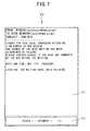
- FIG. 7 is a schematic view illustrating a condition in which contents are displayed in the display region
- FIG. 8 is another schematic view illustrating a condition in which contents are displayed in the display region
- FIG. 9 is a flowchart of startup-time processing of the display terminal.
- FIG. 10 is a flowchart of main processing of the display terminal.
- FIG. 11 is a schematic view illustrating the display region divided into five display management regions.
- the display terminal 1 is roughly rectangular solid-shaped and equipped with an electrophoretic display device 21 on a front surface.
- an electrophoretic display device 21 on a front surface.
- a card slot is formed on a right side surface of the display terminal 1.
- a memory card 23 (see FIG. 2 ) may be inserted into the card slot.
- the display terminal 1 may display a content and auxiliary information of the content that are stored in the memory card 23 on the electrophoretic display device 21.
- auxiliary information that accompanies a content and includes at least information to identify the content is stored in the memory card 23. Besides the information to identify the content, the auxiliary information may as well include various kinds of information about the content that may be set as required. Examples of the information contained in the auxiliary information may include a date and time of creation, a creator, and a data size of the content.
- the operation keys 14 include an up key 141, a down key 142, a right key 143, a left key 144, and a determine key 145.
- the up key 141, the down key 142, the right key 143 and the left key 144 are respectively arranged.
- the up key 141 and the down key 142 may be used to select a content on a table-of-contents screen or on a menu screen.
- the right key 143 and the left key 144 may be used to turn over pages of a displayed content.
- a content stored in the memory card 23 may be displayed or instructions to perform various kinds of setting may be entered.
- a power supply button 15 is provided below the operation keys 14, a power supply button 15 is provided.
- the power supply button 15 may be used for instructing turning on or off of power supply to the display terminal 1.
- the display terminal 1 includes a CPU 10, a display controller 11, a charge controller 12, a memory card interface (I/F) 13, the operation keys 14, the power supply button 15, a ROM 16, a RAM 17, an EEPROM 18, and an RTC (Real Time Clock) 19.
- the CPU 10 controls the display terminal 1.
- Various kinds of information and a display terminal program that controls the operations of the display terminal 1 may be stored in the ROM 16.
- the RAM 17 is a memory that may store various kinds of data temporarily.
- the EEPROM 18 is a nonvolatile memory that may store the identification number of the display terminal 1 etc..
- the RTC 19 measures time.
- the display controller 11 controls display of the information on the electrophoretic display device 21 (see FIG. 1 ).
- a memory card I/F 13 controls reading of information from the memory card 23 and writing of information to the memory card 23.
- the display terminal 1 When the display terminal 1 is not supplied with power from an external power source (not shown), the display terminal 1 may be driven by power from a battery 22.
- the charge controller 12 controls charging of the battery 22 from the external power supply.
- the physical configuration of the electrophoretic display device 21 will be outlined below with reference to FIGS. 3 to 5 .
- the electrophoretic display device 21 is a nonvolatile display and can hold a display condition even if power supply for the display device 1 is cut off.
- the electrophoretic display device 21 includes a back substrate 50 arranged at a back side of the display terminal 1, a front substrate 60 arranged at a front side of the display terminal 1 to face the back substrate 50, and a display portion 70 formed between the back substrate 50 and the front substrate 60.
- line IV-IV indicates a line parallel to the horizontal line (right-and-left direction in FIG.
- line V-V indicates a line parallel to the vertical line (up-and-down direction in FIG. 1 ) of the display terminal 1.
- the back substrate 50 includes back electrodes 52, a back electrode protection film 51, and a package support portion 53.
- the back electrodes 52 generate an electric field to the display portion 70.
- the back electrode protection film 51 is an insulating film formed by, for example, applying an insulating material over the front side surfaces of the back electrodes 52.
- the package support portion 53 is disposed on the back side of the back electrodes 52, to support the electrophoretic display device 21.
- the back electrode protection film 51 may be made of a material that can give a high degree of insulation. Examples for the material may include a resin film made of polyethylene terephthalate or silica, and inorganic materials such as glass.
- the back electrode protection film 51 and the package support portion 53 are each formed as a plastic substrate (resin film) made of flexible polyethylene terephthalate.
- the back electrodes 52 are a plurality of strip-shaped electrodes made of an electric conductor, to which a constant voltage may be applied.
- the back electrodes 52 are arranged parallel to each other in the horizontal direction (in the direction of line IV-IV).
- the front substrate 60 is arranged to face parallel to the back substrate 50 at a predetermined distance from the back substrate 50.
- the front substrate 60 includes front electrodes 62, a front electrode protection film 61, and a display layer 63.
- the front electrodes 62 generate an electric field to the display portion 70.
- the front electrode protection film 61 is an insulating film formed by, for example, applying an insulating material over the back side surfaces of the front electrodes 62.
- the display layer 63 is formed of a transparent member disposed over the front side surfaces of the front electrodes 62, thus functioning as a display screen.
- the front electrode protection film 61 is made of a material that can give a high degree of transparency.
- the front electrodes 62 are a plurality of band-shaped electrodes made of an electric conductor, to which a constant voltage may be applied.
- the front electrodes 62 are arranged parallel to each other in the vertical direction (in the direction of line V-V).
- the front electrodes 62 are also made of a material that can give a high degree of transparency.
- the front electrode protection film 61 is a plastic substrate (resin film) made of polyethylene terephthalate.
- the front electrodes 62 are transparent electrodes made of indium tin oxide (ITO).
- the display layer 63 is formed of a glass substrate.
- the front substrate 60 is transparent. Therefore, the front substrate 60 may function as a display substrate through which the user can visually recognize the display portion 70 when viewing from the front (from the upper side in FIG. 2 ).
- the spacer 71 is a flexible, plate-like member having a plurality of through-holes formed in a lattice pattern.
- the spacer 71 may be made of synthetic resin such as polyimide or polyethylene terephthalate, for example.
- the spacer 71 is disposed in a gap between the back substrate 50 and the front substrate 60.
- the spacer 71 evenly divides the space between the back substrate 50 and the front substrate 60 into a plurality of small partitioned cells 72 in the lattice arrangement and also supports the back substrate 50 and the front substrate 60.
- the small partitioned cells 72 are each filled with charged particles 331 and 332 as well as a dispersion medium 34.
- the charged particles 331 and 332 are each made of a material that can be charged in the dispersion medium 34.
- the material for the charged particles 331 and 332 may be, for example, a pigment or a dye that is made of an organic or inorganic compound, or a pigment or a dye coated with a synthetic resin.
- a mixture of styrene resin and titanium dioxide is employed for the material of the charged particles 331.
- the charged particles 331 have an average particle diameter of 5 ⁇ m (7 weight percent), and contain the titanium dioxide in an amount of 40 weight percent with respect to the total amount of the particles.
- a mixture of styrene resin and carbon black is employed for the material of the charged particles 332.
- the charged particles 332 have an average particle diameter of 5 ⁇ m (10 weight percent), and contain the carbon black in an amount of 30 weight percent with respect to the total amount of the particles. Accordingly, the charged particles 331 have a color tone of white and the charged particles 332 have a color tone of black.
- the charged particles 331 and the charged particles 332 are oppositely charged, that is, the charged particles 331 are positively charged and the charged particles 332 are negatively charged, or vice versa. In the present embodiment, it is assumed that the charged particles 331 are negatively charged and the charged particles 332 are positively charged.
- Alcohols, hydrocarbon, and silicone oil that can give a high degree of insulation and have a low viscosity may be employed as the dispersion medium 34.
- a paraffin-based solvent Isopar (73 weight percent) made by Exxon Mobil Corporation is employed as the dispersion medium 34. It should be noted that ethanol (10 weight percent) is added as an additive agent to the dispersion medium 34.
- a mask portion 40 is mounted to prevent the user from visually recognizing a peripheral portion of the display portion 70 where the small partitioned cells 72 are not present in the front view.
- the mask portion 40 is a plate-like frame member that surrounds a through-hole with a constant width, and runs along the four sides of the front substrate 60.
- the mask portion 40 may be formed by applying colored synthetic resin such as polyethylene terephthalate or by printing a layer of ink onto the surface of the display layer 63. In such a manner, the electrophoretic display device 21 has a configuration that permits the user to visually recognize the display portion 70 through the through-hole formed in the mask portion 40.
- the display region 210 of the electrophoretic display device 21 refers to a region that can be visually recognized through the through-hole formed in the mask portion 40 of the electrophoretic display device 21 described with reference to FIGS. 3 to 5 .
- the display region 210 of the electrophoretic display device 21 may include a first display region 211 and a second display region 212.
- the first display region 211 may be a main region in which main information may be displayed in response to an operation of the user to the display terminal 1.
- a menu screen, a setting screen, or a content may be displayed.
- the second display region 212 information that supplements the main information displayed in the first display region 211 or auxiliary information about the display terminal 1 may be displayed.
- adjunct information of the content for example, may appear as the information that supplements the main information.
- auxiliary information about the display terminal 1 may be, for example, a remaining battery level of the battery 22 of the display terminal 1 or present date and time. Notification information that notifies that power supply for the display terminal 1 has been cut off may be another example of the auxiliary information.
- the second display region 212 displays adjunct information of the content displayed in the first display region 211 or notification information that indicates that power supply to the display terminal 1 has been cut off.
- the second display region 212 displays a saving location (folder 1), a content name (document 1), and a page number of the currently displayed page and the total number of pages (1/3).
- a dotted line border line between the first display region 211 and the second display region 212) shown in FIG. 7 is given for a descriptive purpose to differentiate the two regions. Accordingly, the dotted line will not actually be displayed on the electrophoretic display device 21.
- the first display region 211 occupies a larger area than the second display region 212.
- the first display region 211 occupies 90% and the second display region 212 occupies 10% of the total area of the display region 210.
- the second display region 212 is arranged at the bottom of the display region 210 so as not to stand in the way of the content displayed in the first display region 211.
- the user of the display terminal 1 can instruct turning on or off of the power supply by pressing the power supply button 15. If the power supply button 15 or any of the operation keys 14 is pressed when the power supply is off, the operation is taken as an instruction to apply power. In such a case, power will be supplied to the CPU 10 and the peripheral devices, thus starting up the display terminal 1. On the other hand, if the power supply button 15 is pressed when the power is on, the operation is taken as an instruction to cut off the power supply. In such a case, processing of turning off the power will be performed, thus cutting off power supply to the CPU 10 and the peripheral devices. In addition, if the user performs no operation for a predetermined time, the display terminal 1 can be considered as not in use. In such a case, the processing to turn off the power will be performed, thus cutting off power supply to the CPU 10 and the peripheral devices.
- a message saying "POWER SUPPLY IS OFF" appears in the second display region 212 (see FIG. 8 ).
- the user can know the power of the display terminal 1 is off when the user is going to use the display terminal 1. Therefore, the user can recognize that the display terminal 1 will not respond immediately after the user operates a key, but start-up operations will be performed prior to the processing corresponding to any of the operation keys 14 operated by the user.
- Startup-time processing shown in FIG. 9 will be initiated when the power of the display terminal 1 is turned on, that is, when supply of power begins. Specifically, the processing will be initiated when the power supply button 15 or any of the operation keys 14 is pressed.
- Main processing shown in FIG. 10 will be performed by the CPU 10 executing the display terminal program stored in the ROM 16, when the system is started up by the startup-time processing.
- display information stored in the EEPROM 18 is acquired (S11) .
- the display information refers to information that indicates the information which has been displayed on the electrophoretic display device 21 when power supply to the display terminal 1 has been cut off and which has been stored in a predetermined storage area in the EEPROM 18 (see step S20).
- the display information that has been stored at that time is acquired at step S11.
- the auxiliary information corresponding to the content currently displayed in the first display region 211 is displayed in the second display region 212 (S12).
- the content currently displayed in the first display region 211 is a content that was displayed when power supply was cut off and that has been held even after the power supply was cut off. For example, if a content is displayed in the first display region 211, a saving location, a name of the content and the number of pages may be displayed in the second display region 212. Further, if a menu screen is displayed in the first display region 211, an illustration which indicates the remaining battery level may be displayed.
- timer measurement is started (S13). Specifically, a timer storage area (not shown) arranged in the RAM 17 is initialized. One (1) is added to a value stored in the timer storage area by a time measurement program (not shown) each time a predetermined time period (for example, one second) has passed. Therefore, by referring to the value in the timer storage area, it is possible to acquire an elapsed time from the start of timer measurement.
- a predetermined time period has passed while no operation has been performed by the user, power supply to the display terminal 1 is cut off. Therefore, timer measurement will be carried out in order to measure an elapsed time during which the user has performed no operation.
- a value that indicates a predetermined time period is stored in the ROM 16 or the EEPROM 18. The value may be set beforehand or may be set by the user with display terminal 1.
- a key operation it is determined whether a key operation is performed. Specifically, it is determined whether any of the operation keys 14 or the power supply button 15 is operated (S14). If no key operation is performed (NO at S14), it is determined whether the predetermined time period has passed, referring to the timer storage area (S15). If the predetermined time period has not passed (NO at S15), the process returns to step S14, and determination on the key operation is made again. If any of the operation keys 14 or the power supply button 15 is pressed and it is determined that key operation is performed (YES at S14), zero (0) is stored in the timer storage area and timer measurement is reset (S16).
- step S19 to perform processing of turning off the power (S19 to S22) . If the pressed key is not the power supply button 15 (NO at S17), other processing is performed, corresponding to the pressed key among the operation keys 14 (S18). For example, if the right key 143 is pressed (for turning over a page) when a content is being displayed, the content displayed in the first display region 211 are updated with the next page. Then, the process returns to step S14.
- step S14 each time any of the operation keys 14 is operated (YES at S14), timer measurement is reset to start measuring a time over which the user has performed no operation (S16), and the processing that corresponds to the operated key of the operation keys 14 is performed (S18). If the value stored in the timer storage area becomes larger than the value indicating the predetermined time before any key is operated , that is, the predetermined time period has passed without any key operations (YES at S15), the process proceeds to step S19 to perform the processing to turn off the power (S19 to S22).
- the message saying "POWER SUPPLY IS OFF" is displayed in the second display region 212 as the notification information to indicate that power supply to the display terminal 1 has been cut off (S19). Then, the display information about the information currently displayed in the first display region 211 is stored into the EEPROM 18 (S20) . Based on the thus stored information, the content displayed on the electrophoretic display device 21 will be updated when the display terminal 1 is started up later. Subsequently, power supply to the peripheral devices is cut off (S21) and power supply to the CPU 10 is cut off (S22), thus ending the main processing.
- the power supply may be cut off if the instruction for cutting off the power supply is made by pressing the power supply button 15, or if no key operation is performed for the predetermined time.
- the message saying "POWER SUPPLY IS OFF" appears, which is an example of the notification information indicating that power supply to the display terminal 1 has been cut off.
- the user can know that power supply to the display terminal 1 has been cut off. Therefore, the user can recognize that the user needs to perform operations to turn on the power.
- the user can recognize that the display terminal 1 will not respond immediately even if he presses the power supply button 15 or any of the operation keys 14, because the display terminal 1 will be initialized first. Accordingly, the user may not be confused in operating the display terminal 1.
- the content displayed in the second display region 212 of the display region 210 may be updated, while the content displayed in other display regions, for example, in the first display region 211, may remain unchanged. Therefore, even after power supply is cut off, the user can view information (for example, a content) displayed in the first display region 211. Further, because only the content displayed in the second display region 212 is updated, no extra power will be consumed, and a time to update the information can be reduced. Moreover, when power supply is restarted, the content displayed in the second display region 212 may be updated with information corresponding to a type of information that had been displayed before power supply was cut off. Accordingly, the notification information that indicates power supply has been cut off may not remain displayed after restart of the power supply. Further, because the information corresponding to the type of information that had been displayed before power supply was cut off may be displayed, the user can use the display terminal 1 in the same way as before the power supply was cut off.
- the display terminal 1 of the present disclosure is not limited to the above-described embodiment, but of course may be changed variously without departing from the gist of the present disclosure.
- the notification information to indicate that power supply to the display terminal 1 has been cut off the message saying "POWER SUPPLY IS OFF" is displayed.
- the notification information is not limited to the message but only needs to indicate that power supply to the display terminal 1 has been cut off.
- the notification information may be, for example, an illustration, pictographic characters, a pattern, a frame enclosing the entire display region 120, or a frame enclosing specific characters or information.
- a content and auxiliary information of the content are stored in the memory card 23.
- a hard disk drive may be installed in the display terminal 1 to store the content and the auxiliary information.
- the content and the auxiliary information may be stored in the EEPROM 18 or in the RAM 16.
- the notification information is displayed in the second display region 212, which presents information to supplement the main information displayed in the first display region 211 or the notification information for the user.
- the notification information is displayed in a partial region of the display region 210.
- the second display region 212 is arranged at the bottom of the display region 210.
- the layout of the first display region 211 and the second display region 212 in the display region 210 is not limited to the layout employed in the above-described embodiment.
- the second display region may be arranged at the upper, right, or left end of the display region 210.
- the layout of the first display region and the second display region in the display region 210 may be changed in accordance with contents of the information displayed in the first display region. For example, if a content is displayed in the first display region, the second display region may be arranged at the bottom as shown in FIGS. 6 to 8 . On the other hand, the second display region may be arranged at the right end on the menu screen.
- the partial region of the display region 210 in which the notification information is displayed is not limited to the second display region 212.
- the notification information may be displayed in the first display region 211. Further, the notification information may be displayed near an edge of the first display region 211, such as a top, bottom, left end, right end, upper left corner, upper right corner, lower left corner, or lower right corner. Further, the notification information may be displayed at a peripheral part of the display region 210. In such a case, a possibility that the notification information stands in the way of the information displayed in the first display region 211 may be reduced. On the other hand, the notification information may be displayed at the midsection of the display region 210 in order to make the notification information conspicuous.
- only the second display region 212 may be updated upon startup of the display terminal 1.
- only the pixels configuring the second display region 212 may be updated in display.
- the region to be updated at step S12 upon startup may not be only the second display region 212.
- the entirety of the display region 210 of the electrophoretic display device 21, that is, the first display region 211 and the second display region 212 may be updated.
- the first display region 211 and the second display region 212 may be defined by dividing the display region 120 in terms of displayed contents.
- the display region 120 may be divided into several regions for management of display updating. In such a case, only a region including the second display region 212 may be updated in display.
- the display region 120 is divided into five regions 221 to 225 for management of display updating. The five regions 221 to 225 are obtained by horizontally dividing the display region 120 and each region occupies 20% of the area of the display region 120.
- the second display region 212 (see FIGS. 6 to 8 ) may be included in the bottom region 221.
- step S12 only the pixels configuring the region 221 may be updated.
- the time required in update can be reduced as compared to the case of updating the entire display region 120. Also, power required in update can be decreased.
Landscapes
- Engineering & Computer Science (AREA)
- Physics & Mathematics (AREA)
- Computer Hardware Design (AREA)
- General Physics & Mathematics (AREA)
- Theoretical Computer Science (AREA)
- Control Of Indicators Other Than Cathode Ray Tubes (AREA)
- Electrochromic Elements, Electrophoresis, Or Variable Reflection Or Absorption Elements (AREA)
- Digital Computer Display Output (AREA)
- Controls And Circuits For Display Device (AREA)
- Telephone Function (AREA)
Applications Claiming Priority (1)
| Application Number | Priority Date | Filing Date | Title |
|---|---|---|---|
| JP2008042493A JP2009198936A (ja) | 2008-02-25 | 2008-02-25 | 表示端末及び表示端末プログラム |
Publications (2)
| Publication Number | Publication Date |
|---|---|
| EP2093750A2 true EP2093750A2 (de) | 2009-08-26 |
| EP2093750A3 EP2093750A3 (de) | 2010-09-15 |
Family
ID=40602404
Family Applications (1)
| Application Number | Title | Priority Date | Filing Date |
|---|---|---|---|
| EP09001536A Withdrawn EP2093750A3 (de) | 2008-02-25 | 2009-02-04 | Anzeigeendgerät und computerlesbares Medium mit darauf gespeichertem Anzeigeendgeräteprogramm |
Country Status (3)
| Country | Link |
|---|---|
| US (1) | US8194062B2 (de) |
| EP (1) | EP2093750A3 (de) |
| JP (1) | JP2009198936A (de) |
Cited By (1)
| Publication number | Priority date | Publication date | Assignee | Title |
|---|---|---|---|---|
| EP2600333A3 (de) * | 2011-12-01 | 2014-01-15 | Glocal Services UG | Baustelleninformationsvorrichtung |
Families Citing this family (1)
| Publication number | Priority date | Publication date | Assignee | Title |
|---|---|---|---|---|
| JP5479808B2 (ja) * | 2009-08-06 | 2014-04-23 | 株式会社ジャパンディスプレイ | 表示装置 |
Citations (1)
| Publication number | Priority date | Publication date | Assignee | Title |
|---|---|---|---|---|
| JP2007187927A (ja) | 2006-01-13 | 2007-07-26 | Brother Ind Ltd | 閲覧端末及び閲覧端末プログラム |
Family Cites Families (15)
| Publication number | Priority date | Publication date | Assignee | Title |
|---|---|---|---|---|
| JPH06295165A (ja) * | 1993-04-09 | 1994-10-21 | Sharp Corp | 反強誘電性液晶パネルの駆動方法 |
| JPH08160395A (ja) * | 1994-10-07 | 1996-06-21 | Canon Inc | 表示装置 |
| JP3827823B2 (ja) * | 1996-11-26 | 2006-09-27 | シャープ株式会社 | 液晶表示画像の消去装置及びそれを備えた液晶表示装置 |
| JP3105884B2 (ja) * | 1999-03-31 | 2000-11-06 | 新潟日本電気株式会社 | メモリ性表示装置用表示コントローラ |
| JP2001211270A (ja) * | 2000-01-25 | 2001-08-03 | Minolta Co Ltd | 電気機器、電気機器への広告方法、課金システム及び課金方法 |
| TWI221595B (en) * | 2000-09-29 | 2004-10-01 | Sanyo Electric Co | Driving apparatus for display device |
| JP2002116905A (ja) * | 2000-10-06 | 2002-04-19 | Matsushita Electric Ind Co Ltd | 情報処理装置 |
| KR100766970B1 (ko) * | 2001-05-11 | 2007-10-15 | 삼성전자주식회사 | 디스플레이장치의 초기설정시스템 및 그 제어방법 |
| JP4151325B2 (ja) * | 2002-07-02 | 2008-09-17 | 株式会社ニコン | 電子カメラ |
| JP2005266191A (ja) * | 2004-03-18 | 2005-09-29 | Fuji Xerox Co Ltd | 電子ペーパーシステム |
| WO2006049105A1 (ja) * | 2004-11-04 | 2006-05-11 | Nikon Corporation | 表示装置および電子装置 |
| JP2006139145A (ja) | 2004-11-12 | 2006-06-01 | Canon Inc | 液晶ディスプレイ及びその制御方法、画像入出力装置、並びにプログラム及び記憶媒体 |
| JP2006256182A (ja) * | 2005-03-18 | 2006-09-28 | Ricoh Co Ltd | 画像形成装置 |
| JP4668984B2 (ja) * | 2005-03-29 | 2011-04-13 | 富士通株式会社 | 表示素子の駆動方法 |
| JP2007286602A (ja) * | 2006-03-24 | 2007-11-01 | Ricoh Co Ltd | 表示装置および表示システム |
-
2008
- 2008-02-25 JP JP2008042493A patent/JP2009198936A/ja active Pending
-
2009
- 2009-02-04 EP EP09001536A patent/EP2093750A3/de not_active Withdrawn
- 2009-02-25 US US12/392,837 patent/US8194062B2/en not_active Expired - Fee Related
Patent Citations (1)
| Publication number | Priority date | Publication date | Assignee | Title |
|---|---|---|---|---|
| JP2007187927A (ja) | 2006-01-13 | 2007-07-26 | Brother Ind Ltd | 閲覧端末及び閲覧端末プログラム |
Cited By (1)
| Publication number | Priority date | Publication date | Assignee | Title |
|---|---|---|---|---|
| EP2600333A3 (de) * | 2011-12-01 | 2014-01-15 | Glocal Services UG | Baustelleninformationsvorrichtung |
Also Published As
| Publication number | Publication date |
|---|---|
| US20090213106A1 (en) | 2009-08-27 |
| JP2009198936A (ja) | 2009-09-03 |
| EP2093750A3 (de) | 2010-09-15 |
| US8194062B2 (en) | 2012-06-05 |
Similar Documents
| Publication | Publication Date | Title |
|---|---|---|
| JP5136272B2 (ja) | 携帯型表示端末及びプログラム | |
| CN102998828B (zh) | 具备液晶百叶窗的电子设备 | |
| CN102981749A (zh) | 信息阅览装置和控制程序以及控制方法 | |
| US20130139045A1 (en) | Information browsing apparatus and recording medium for computer to read, storing computer program | |
| JP2002312104A (ja) | 電子装置及び電子装置用情報表示方法 | |
| US20110157203A1 (en) | Electronic apparatus with multiple screens and image displaying method thereof | |
| WO2011001671A1 (ja) | 情報処理装置、及び情報処理装置の制御方法 | |
| JP2010039372A (ja) | 携帯型表示端末及びプログラム | |
| US20090237388A1 (en) | Display terminal and computer-readable recording medium recording display terminal program | |
| KR100679536B1 (ko) | 정보 처리 장치 및 전력 제어 방법 | |
| JP2010086089A (ja) | 携帯型表示端末及びプログラム | |
| US20110134097A1 (en) | Display device and computer readable storage medium recording program | |
| US8194062B2 (en) | Display terminal and computer-readable medium storing display terminal program | |
| US9196214B2 (en) | Display device | |
| JP5775622B2 (ja) | 液晶シャッタを備える電子機器および方法 | |
| KR20060008872A (ko) | 이미지를 디스플레이하고 저장하기 위한 디스플레이 및방법 | |
| US20090244075A1 (en) | Browsing terminal | |
| JP2011180789A (ja) | 表示装置及びプログラム | |
| JP2007187927A (ja) | 閲覧端末及び閲覧端末プログラム | |
| JP2010039370A (ja) | 携帯型表示端末及びプログラム | |
| US12148326B2 (en) | Electronic label and display method thereof | |
| JP2010169886A (ja) | 画像表示装置および画像表示プログラム | |
| JP5282595B2 (ja) | 表示装置、表示方法及び表示プログラム。 | |
| US20110285725A1 (en) | Display control method, display control device and program | |
| JP2010231039A (ja) | 表示装置、表示方法及びプログラム。 |
Legal Events
| Date | Code | Title | Description |
|---|---|---|---|
| PUAI | Public reference made under article 153(3) epc to a published international application that has entered the european phase |
Free format text: ORIGINAL CODE: 0009012 |
|
| AK | Designated contracting states |
Kind code of ref document: A2 Designated state(s): AT BE BG CH CY CZ DE DK EE ES FI FR GB GR HR HU IE IS IT LI LT LU LV MC MK MT NL NO PL PT RO SE SI SK TR |
|
| AX | Request for extension of the european patent |
Extension state: AL BA RS |
|
| PUAL | Search report despatched |
Free format text: ORIGINAL CODE: 0009013 |
|
| AK | Designated contracting states |
Kind code of ref document: A3 Designated state(s): AT BE BG CH CY CZ DE DK EE ES FI FR GB GR HR HU IE IS IT LI LT LU LV MC MK MT NL NO PL PT RO SE SI SK TR |
|
| AX | Request for extension of the european patent |
Extension state: AL BA RS |
|
| 17P | Request for examination filed |
Effective date: 20110315 |
|
| AKX | Designation fees paid |
Designated state(s): AT BE BG CH CY CZ DE DK EE ES FI FR GB GR HR HU IE IS IT LI LT LU LV MC MK MT NL NO PL PT RO SE SI SK TR |
|
| 17Q | First examination report despatched |
Effective date: 20130205 |
|
| STAA | Information on the status of an ep patent application or granted ep patent |
Free format text: STATUS: THE APPLICATION IS DEEMED TO BE WITHDRAWN |
|
| 18D | Application deemed to be withdrawn |
Effective date: 20130618 |