EP2094915B1 - Système hydraulique améliorant maniabilité d'un excavateur pour l'aplanissement - Google Patents
Système hydraulique améliorant maniabilité d'un excavateur pour l'aplanissement Download PDFInfo
- Publication number
- EP2094915B1 EP2094915B1 EP07851716.6A EP07851716A EP2094915B1 EP 2094915 B1 EP2094915 B1 EP 2094915B1 EP 07851716 A EP07851716 A EP 07851716A EP 2094915 B1 EP2094915 B1 EP 2094915B1
- Authority
- EP
- European Patent Office
- Prior art keywords
- boom
- control valve
- switched
- pilot line
- directional control
- Prior art date
- Legal status (The legal status is an assumption and is not a legal conclusion. Google has not performed a legal analysis and makes no representation as to the accuracy of the status listed.)
- Not-in-force
Links
- 239000012530 fluid Substances 0.000 claims description 17
- 238000006073 displacement reaction Methods 0.000 claims description 10
- 238000010586 diagram Methods 0.000 description 6
- 230000002093 peripheral effect Effects 0.000 description 6
- 238000000034 method Methods 0.000 description 4
- XEEYBQQBJWHFJM-UHFFFAOYSA-N Iron Chemical compound [Fe] XEEYBQQBJWHFJM-UHFFFAOYSA-N 0.000 description 2
- 230000001419 dependent effect Effects 0.000 description 2
- 238000010409 ironing Methods 0.000 description 2
- 230000000903 blocking effect Effects 0.000 description 1
- 238000010276 construction Methods 0.000 description 1
- 230000000694 effects Effects 0.000 description 1
- 229910052742 iron Inorganic materials 0.000 description 1
- 230000001788 irregular Effects 0.000 description 1
- 230000007935 neutral effect Effects 0.000 description 1
Images




Classifications
-
- E—FIXED CONSTRUCTIONS
- E02—HYDRAULIC ENGINEERING; FOUNDATIONS; SOIL SHIFTING
- E02F—DREDGING; SOIL-SHIFTING
- E02F9/00—Component parts of dredgers or soil-shifting machines, not restricted to one of the kinds covered by groups E02F3/00 - E02F7/00
- E02F9/20—Drives; Control devices
-
- E—FIXED CONSTRUCTIONS
- E02—HYDRAULIC ENGINEERING; FOUNDATIONS; SOIL SHIFTING
- E02F—DREDGING; SOIL-SHIFTING
- E02F3/00—Dredgers; Soil-shifting machines
- E02F3/04—Dredgers; Soil-shifting machines mechanically-driven
- E02F3/28—Dredgers; Soil-shifting machines mechanically-driven with digging tools mounted on a dipper- or bucket-arm, i.e. there is either one arm or a pair of arms, e.g. dippers, buckets
- E02F3/36—Component parts
- E02F3/42—Drives for dippers, buckets, dipper-arms or bucket-arms
- E02F3/43—Control of dipper or bucket position; Control of sequence of drive operations
- E02F3/435—Control of dipper or bucket position; Control of sequence of drive operations for dipper-arms, backhoes or the like
- E02F3/437—Control of dipper or bucket position; Control of sequence of drive operations for dipper-arms, backhoes or the like providing automatic sequences of movements, e.g. linear excavation, keeping dipper angle constant
-
- E—FIXED CONSTRUCTIONS
- E02—HYDRAULIC ENGINEERING; FOUNDATIONS; SOIL SHIFTING
- E02F—DREDGING; SOIL-SHIFTING
- E02F9/00—Component parts of dredgers or soil-shifting machines, not restricted to one of the kinds covered by groups E02F3/00 - E02F7/00
- E02F9/14—Booms only for booms with cable suspension arrangements; Cable suspensions
-
- E—FIXED CONSTRUCTIONS
- E02—HYDRAULIC ENGINEERING; FOUNDATIONS; SOIL SHIFTING
- E02F—DREDGING; SOIL-SHIFTING
- E02F9/00—Component parts of dredgers or soil-shifting machines, not restricted to one of the kinds covered by groups E02F3/00 - E02F7/00
- E02F9/20—Drives; Control devices
- E02F9/22—Hydraulic or pneumatic drives
- E02F9/2203—Arrangements for controlling the attitude of actuators, e.g. speed, floating function
-
- E—FIXED CONSTRUCTIONS
- E02—HYDRAULIC ENGINEERING; FOUNDATIONS; SOIL SHIFTING
- E02F—DREDGING; SOIL-SHIFTING
- E02F9/00—Component parts of dredgers or soil-shifting machines, not restricted to one of the kinds covered by groups E02F3/00 - E02F7/00
- E02F9/20—Drives; Control devices
- E02F9/22—Hydraulic or pneumatic drives
- E02F9/2221—Control of flow rate; Load sensing arrangements
- E02F9/2239—Control of flow rate; Load sensing arrangements using two or more pumps with cross-assistance
-
- E—FIXED CONSTRUCTIONS
- E02—HYDRAULIC ENGINEERING; FOUNDATIONS; SOIL SHIFTING
- E02F—DREDGING; SOIL-SHIFTING
- E02F9/00—Component parts of dredgers or soil-shifting machines, not restricted to one of the kinds covered by groups E02F3/00 - E02F7/00
- E02F9/20—Drives; Control devices
- E02F9/22—Hydraulic or pneumatic drives
- E02F9/2264—Arrangements or adaptations of elements for hydraulic drives
- E02F9/2267—Valves or distributors
-
- E—FIXED CONSTRUCTIONS
- E02—HYDRAULIC ENGINEERING; FOUNDATIONS; SOIL SHIFTING
- E02F—DREDGING; SOIL-SHIFTING
- E02F9/00—Component parts of dredgers or soil-shifting machines, not restricted to one of the kinds covered by groups E02F3/00 - E02F7/00
- E02F9/20—Drives; Control devices
- E02F9/22—Hydraulic or pneumatic drives
- E02F9/2278—Hydraulic circuits
- E02F9/2285—Pilot-operated systems
-
- E—FIXED CONSTRUCTIONS
- E02—HYDRAULIC ENGINEERING; FOUNDATIONS; SOIL SHIFTING
- E02F—DREDGING; SOIL-SHIFTING
- E02F9/00—Component parts of dredgers or soil-shifting machines, not restricted to one of the kinds covered by groups E02F3/00 - E02F7/00
- E02F9/20—Drives; Control devices
- E02F9/22—Hydraulic or pneumatic drives
- E02F9/2278—Hydraulic circuits
- E02F9/2292—Systems with two or more pumps
-
- F—MECHANICAL ENGINEERING; LIGHTING; HEATING; WEAPONS; BLASTING
- F15—FLUID-PRESSURE ACTUATORS; HYDRAULICS OR PNEUMATICS IN GENERAL
- F15B—SYSTEMS ACTING BY MEANS OF FLUIDS IN GENERAL; FLUID-PRESSURE ACTUATORS, e.g. SERVOMOTORS; DETAILS OF FLUID-PRESSURE SYSTEMS, NOT OTHERWISE PROVIDED FOR
- F15B13/00—Details of servomotor systems ; Valves for servomotor systems
- F15B13/02—Fluid distribution or supply devices characterised by their adaptation to the control of servomotors
- F15B13/021—Valves for interconnecting the fluid chambers of an actuator
-
- F—MECHANICAL ENGINEERING; LIGHTING; HEATING; WEAPONS; BLASTING
- F15—FLUID-PRESSURE ACTUATORS; HYDRAULICS OR PNEUMATICS IN GENERAL
- F15B—SYSTEMS ACTING BY MEANS OF FLUIDS IN GENERAL; FLUID-PRESSURE ACTUATORS, e.g. SERVOMOTORS; DETAILS OF FLUID-PRESSURE SYSTEMS, NOT OTHERWISE PROVIDED FOR
- F15B13/00—Details of servomotor systems ; Valves for servomotor systems
- F15B13/02—Fluid distribution or supply devices characterised by their adaptation to the control of servomotors
- F15B13/04—Fluid distribution or supply devices characterised by their adaptation to the control of servomotors for use with a single servomotor
- F15B13/0401—Valve members; Fluid interconnections therefor
- F15B2013/0413—Valve members; Fluid interconnections therefor with four or more positions
-
- F—MECHANICAL ENGINEERING; LIGHTING; HEATING; WEAPONS; BLASTING
- F15—FLUID-PRESSURE ACTUATORS; HYDRAULICS OR PNEUMATICS IN GENERAL
- F15B—SYSTEMS ACTING BY MEANS OF FLUIDS IN GENERAL; FLUID-PRESSURE ACTUATORS, e.g. SERVOMOTORS; DETAILS OF FLUID-PRESSURE SYSTEMS, NOT OTHERWISE PROVIDED FOR
- F15B2211/00—Circuits for servomotor systems
- F15B2211/30—Directional control
- F15B2211/305—Directional control characterised by the type of valves
- F15B2211/3056—Assemblies of multiple valves
- F15B2211/3059—Assemblies of multiple valves having multiple valves for multiple output members
- F15B2211/30595—Assemblies of multiple valves having multiple valves for multiple output members with additional valves between the groups of valves for multiple output members
-
- F—MECHANICAL ENGINEERING; LIGHTING; HEATING; WEAPONS; BLASTING
- F15—FLUID-PRESSURE ACTUATORS; HYDRAULICS OR PNEUMATICS IN GENERAL
- F15B—SYSTEMS ACTING BY MEANS OF FLUIDS IN GENERAL; FLUID-PRESSURE ACTUATORS, e.g. SERVOMOTORS; DETAILS OF FLUID-PRESSURE SYSTEMS, NOT OTHERWISE PROVIDED FOR
- F15B2211/00—Circuits for servomotor systems
- F15B2211/30—Directional control
- F15B2211/31—Directional control characterised by the positions of the valve element
- F15B2211/3122—Special positions other than the pump port being connected to working ports or the working ports being connected to the return line
-
- F—MECHANICAL ENGINEERING; LIGHTING; HEATING; WEAPONS; BLASTING
- F15—FLUID-PRESSURE ACTUATORS; HYDRAULICS OR PNEUMATICS IN GENERAL
- F15B—SYSTEMS ACTING BY MEANS OF FLUIDS IN GENERAL; FLUID-PRESSURE ACTUATORS, e.g. SERVOMOTORS; DETAILS OF FLUID-PRESSURE SYSTEMS, NOT OTHERWISE PROVIDED FOR
- F15B2211/00—Circuits for servomotor systems
- F15B2211/30—Directional control
- F15B2211/31—Directional control characterised by the positions of the valve element
- F15B2211/3122—Special positions other than the pump port being connected to working ports or the working ports being connected to the return line
- F15B2211/3133—Regenerative position connecting the working ports or connecting the working ports to the pump, e.g. for high-speed approach stroke
-
- F—MECHANICAL ENGINEERING; LIGHTING; HEATING; WEAPONS; BLASTING
- F15—FLUID-PRESSURE ACTUATORS; HYDRAULICS OR PNEUMATICS IN GENERAL
- F15B—SYSTEMS ACTING BY MEANS OF FLUIDS IN GENERAL; FLUID-PRESSURE ACTUATORS, e.g. SERVOMOTORS; DETAILS OF FLUID-PRESSURE SYSTEMS, NOT OTHERWISE PROVIDED FOR
- F15B2211/00—Circuits for servomotor systems
- F15B2211/30—Directional control
- F15B2211/32—Directional control characterised by the type of actuation
- F15B2211/321—Directional control characterised by the type of actuation mechanically
- F15B2211/324—Directional control characterised by the type of actuation mechanically manually, e.g. by using a lever or pedal
-
- F—MECHANICAL ENGINEERING; LIGHTING; HEATING; WEAPONS; BLASTING
- F15—FLUID-PRESSURE ACTUATORS; HYDRAULICS OR PNEUMATICS IN GENERAL
- F15B—SYSTEMS ACTING BY MEANS OF FLUIDS IN GENERAL; FLUID-PRESSURE ACTUATORS, e.g. SERVOMOTORS; DETAILS OF FLUID-PRESSURE SYSTEMS, NOT OTHERWISE PROVIDED FOR
- F15B2211/00—Circuits for servomotor systems
- F15B2211/30—Directional control
- F15B2211/32—Directional control characterised by the type of actuation
- F15B2211/327—Directional control characterised by the type of actuation electrically or electronically
-
- F—MECHANICAL ENGINEERING; LIGHTING; HEATING; WEAPONS; BLASTING
- F15—FLUID-PRESSURE ACTUATORS; HYDRAULICS OR PNEUMATICS IN GENERAL
- F15B—SYSTEMS ACTING BY MEANS OF FLUIDS IN GENERAL; FLUID-PRESSURE ACTUATORS, e.g. SERVOMOTORS; DETAILS OF FLUID-PRESSURE SYSTEMS, NOT OTHERWISE PROVIDED FOR
- F15B2211/00—Circuits for servomotor systems
- F15B2211/30—Directional control
- F15B2211/32—Directional control characterised by the type of actuation
- F15B2211/329—Directional control characterised by the type of actuation actuated by fluid pressure
-
- F—MECHANICAL ENGINEERING; LIGHTING; HEATING; WEAPONS; BLASTING
- F15—FLUID-PRESSURE ACTUATORS; HYDRAULICS OR PNEUMATICS IN GENERAL
- F15B—SYSTEMS ACTING BY MEANS OF FLUIDS IN GENERAL; FLUID-PRESSURE ACTUATORS, e.g. SERVOMOTORS; DETAILS OF FLUID-PRESSURE SYSTEMS, NOT OTHERWISE PROVIDED FOR
- F15B2211/00—Circuits for servomotor systems
- F15B2211/30—Directional control
- F15B2211/355—Pilot pressure control
-
- F—MECHANICAL ENGINEERING; LIGHTING; HEATING; WEAPONS; BLASTING
- F15—FLUID-PRESSURE ACTUATORS; HYDRAULICS OR PNEUMATICS IN GENERAL
- F15B—SYSTEMS ACTING BY MEANS OF FLUIDS IN GENERAL; FLUID-PRESSURE ACTUATORS, e.g. SERVOMOTORS; DETAILS OF FLUID-PRESSURE SYSTEMS, NOT OTHERWISE PROVIDED FOR
- F15B2211/00—Circuits for servomotor systems
- F15B2211/60—Circuit components or control therefor
- F15B2211/635—Circuits providing pilot pressure to pilot pressure-controlled fluid circuit elements
- F15B2211/6355—Circuits providing pilot pressure to pilot pressure-controlled fluid circuit elements having valve means
Definitions
- the present invention relates to a hydraulic system according to the preamble of claim 1 which is known from EP 0 436 740 A1 .
- US 3 604 313 discloses a hydraulic circuit for the operation of a boom of a construction machine which includes a four-position boom control valve for controlling the position that the boom hydraulic actuator may assume during operations.
- US 2003/230082 A1 discloses a hydraulic system comprising a first and second pump, a boom cylinder which drives a boom, first and second control valves including boom-up side ports hydraulically connected to a boom-up pilot line, the hydraulic operating fluid passing through the first and second boom control valves being joined and supplied to the boom cylinder when the boom is lifted.
- the flatting work of a plain or inclined ground is carried out as a part of compacting work after the ground is leveled.
- a bucket of the excavator is pulled, while pressing the ground in the state in which a flat part of the bucket is in contact with the ground, thereby pressing and simultaneously flattening the ground, similarly ironing clothes with iron.
- the flatting work is carried out by combined operation of a boom, an arm and a bucket with pressing the ground and simultaneously pulling the arm in the state in which the flat part of the bucket is in contact with the ground, which is essential work for making a flatly pressed surface in the plain or inclined ground
- the force pressing the ground must be uniform to some extent. Meanwhile, if the ground is pressed with excessive or non-uniform force, the pressing work causes a problem with uniformity in flatness of the ground.
- the force pressing the ground is determined by mechanical force applied to the bucket through the combined operation of the boom, the arm and the bucket. However, it is not easy to properly apply the mechanical force to the ground. This can be realized only by skilled operation of a joystick of the excavator. Further, in addition to the application of the uniform force, the flat part of the bucket must be continuously in contact with the ground.
- the boom, the arm and the bucket of the excavator are operated by the joystick.
- the typical joystick of the excavator is provided with a swing lever for swinging a body of the excavator and an arm lever for dump/crowd operation of the arm, which are installed on one side within driver's reach, and a lever for up/down operation of the boom and a lever for dump/crowd operation of the bucket, which are installed on the other side within driver's reach.
- the results of the work are dependent on how properly the joystick is operated.
- an object of the present invention is to provide a hydraulic system for an excavator, which enables even an unskilled operator, who is short of skill or technique of the operation of equipment, to easily perform flatting work on a plain or inclined ground.
- the present invention provides a hydraulic system for an excavator according to independent claim 1.
- the fourth position of the boom control valve is located at one outermost port of the boom control valve, and the stopper is connected to the other outermost port of the boom control valve and supplies a predetermined hydraulic pressure to the other outermost port so as to restrict the boom control valve from being switched to the fourth position.
- the first position of the directional control switch corresponds to a position that is indicated by Mode 1 in FIGS. 3 and 4 , which is for the excavating work. Further, the second position of the directional control switch corresponds to a position that is indicated by Mode 2 in FIGS. 3 and 4 , which is for the flatting work.
- the boom control valve in order to allow the ordinary excavating work to be carried out even if the directional control switch is switched so as to select the flatting work position, the boom control valve is switched up to the fourth position only when the boom-up side port thereof has pressure equal to or greater than a preset reference pressure, and is switched only to one of the first, second and third positions when the pressure of the boom-up side port is less than the reference pressure.
- the reference pressure is set to pressure occurring at the boom-up side port when an operator operates an operating lever beyond a predetermined displacement or angle in a direction where the boom is lifted.
- the hydraulic system for the excavator which is structurally improved so as to easily perform flatting work, can be applied to a two-pump hydraulic system having two pumps.
- the hydraulic system of the present invention further comprises means for interrupting the connection of the boom-up pilot line and the second boom control valve.
- One example of the interrupting means includes a second directional control valve, which can be switched between a first position where the boom-up pilot line is connected with the second boom control valve and a second position where the boom-up pilot line is disconnected from the second boom control valve.
- the hydraulic system according to an example of the present invention further comprises a directional control switch for switching the first directional control valve and the second directional control valve.
- the two-pump hydraulic system can be also designed so that, in order to allow the ordinary excavating work to be carried out even if the directional control switch is switched so as to select the flatting work position, when the directional control switch is switched to a first position, the first boom control valve is switched up to the fourth position only when the boom-up side port thereof has pressure equal to or greater than a preset reference pressure, and is switched only to one of the first, second and third positions when the pressure of the boom-up side port is less than the reference pressure.
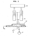
- FIG. 1 is a schematic view illustrating configuration of a boom control valve 22 and its peripheral attachments in an ordinary excavator having a boom, an arm and a bucket.
- a boom control valve 22 can be switched to one of three positions: one for lifting a boom 24, one for maintaining neutrality of the boom 24, and one for lowering the boom 24, when viewed from the left side.
- FIG. 2 is a schematic view illustrating configuration of a boom control valve 22 and its peripheral attachments in an excavator according to an embodiment of the present invention.
- the boom control valve 22 has a first position for maintaining neutrality of a boom 24, a second position for lifting the boom 24, a third position for lowering the boom 24, and a fourth position for allowing the boom 24 to be lifted and lowered by self-weight or external force.
- the boom control valve 22 can be switched to one of the four positions.
- the boom control valve 22 can be operated by a boom-up pilot signal Pi and a boom down pilot signal, which are generated by manipulation of a joystick of an excavator operator (see FIG. 5 ).
- the flatting work can be done by operating only the bucket and arm in the state in which the boom control valve is fixed to a preset position, i.e. the fourth position.
- the boom control valve is fixed to the fourth position, the arm is stretched to the maximum extent, and thereby the bucket is located at a place remotest from a body of the excavator, as illustrated in FIGS. 7 and 8 .
- a flat outer surface of the bucket is controlled to be parallel to the ground.
- an arm controlling joystick is controlled toward a crowd side, so that the flatting work is naturally carried out while the arm is pulled.
- the bucket must be controlled such that the flat outer surface thereof is parallel to the ground.
- the flat outer surface of the bucket has only to be minutely controlled while performing simple operation of pulling the arm (arm crowd operation), the flatting work can be easily carried out.
- the hydraulic system comprises a stopper 11, which controls the boom control valve 22 to prevent from being arbitrarily switched to the fourth position.
- the boom control valve 22 is further provided with the stopper 11 on one side thereof which restricts the boom control valve 22 from being switched to the fourth position so as to allow the boom control valve 22 to be switched only to one of the first, second and third positions.
- the boom control valve 22 has the fourth position adjacent to a boom-up side port thereof, that is, one outermost port thereof, and the stopper 11 is connected to another outermost port, that is, a boom-down side port.
- the application of a predetermined hydraulic pressure to the stopper restricts the boom control valve 22 from being switched to the fourth position.
- the hydraulic system of the present invention can further comprise a first directional control valve 8 for controlling the stopper.
- the hydraulic system further comprises a gear pump 9, and a pilot line Pi2 connecting the stopper 11 and the gear pump 9.
- the first directional control valve can be installed on the pilot line Pi2.
- the hydraulic system of the present invention can further comprise a directional control switch 20.
- a work mode is determined by the directional control switch.
- the boom control valve 22 can be adapted to be switched to the fourth position. In the other cases, the boom control valve 22 can be adapted to be not switched to the fourth position.
- the directional control switch 20 can be selectively switched to one of a first position (Mode 1) and a second position (Mode 2) by manipulation of an operator.
- the directional control switch is provided in a knob shape at a predetermined position within a cab (not shown), and is electrically connected with the solenoid-type first directional control valve 8 as described below as well as a second directional control valve 10 in the next embodiment, which will be described below.
- the first position of the directional control switch 20 refers to a position where the first directional control valve 8 is switched to the first position so as to allow the stopper 11 to communicate with the gear pump 9 through the pilot line Pi2.
- the second position of the directional control switch 20 refers to a position where the first directional control valve 8 is switched to the second position so as to allow the pilot line Pi2 to communicate with a tank T.
- the stopper 11 releases its function, so that the boom control valve 22 can be switched to the fourth position.
- the first position of the directional control switch 20 corresponds to a position that is indicated by Mode 1 in FIGS. 3 and 4 , which is for the excavating work.
- the second position of the directional control switch 20 corresponds to a position that is indicated by Mode 2 in FIGS. 3 and 4 , which is for the flatting work.
- the directional control switch 20 may be adapted to carry out the ordinary excavating work.
- a boom-up side hydraulic line Pi of the boom control valve 22 has pressure equal to and greater than a preset reference pressure, for instance 26k
- the boom control valve 22 can be adapted to be switched to the fourth position.
- a first boom control valve is adapted to be switched only to one of the first, second and third positions so as to be able to carry out the ordinary excavating work.
- the pressure occurring when the operator pulls the operation lever of the joystick at a displacement of 10 mm in the direction where the boom is lifted can be set to become the preset reference pressure of the hydraulic line.
- the first boom control valve can be adapted to be switched only to one of the first, second and third positions.
- the first boom control valve can be adapted to be switched to one of the first through fourth positions.
- FIG. 3 is a hydraulic circuit diagram illustrating a two-pump hydraulic system having two pumps according to an example of the present invention.
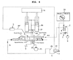
- FIG. 4 schematically illustrates the first boom control valve 1 and its peripheral attachments in the hydraulic circuit diagram of FIG. 3 .
- FIG. 5 is a hydraulic circuit diagram illustrating a joystick that is an operating device of the excavator.
- the hydraulic system illustrated in FIG. 3 comprises first and second pumps P1 and P2, a control valve section 21, an arm crowd pilot line Pac, a boom-up pilot line Pi, a first directional control valve 8, and a second directional control valve 10.
- control valve section 21 includes first and second boom control valves 2 and 3, first and second arm control valves 4 and 5, and other valves such as a straight traveling control valve, a left/right turning control valve, an option control valve and a swing control valve.
- first and second boom control valves 2 and 3 first and second arm control valves 4 and 5, and other valves such as a straight traveling control valve, a left/right turning control valve, an option control valve and a swing control valve.
- other valves such as a straight traveling control valve, a left/right turning control valve, an option control valve and a swing control valve.
- first boom control valve 2 and the second arm control valve 5 communicate with the first pump P1 through a center parallel line Ps.
- the second boom control valve 3 and the first arm control valve 4 communicate with the second pump P2 through another center parallel line Ps.
- Hydraulic operating fluid passing through the second boom control valve 3 joins that passing through the first boom control valve 2 via a predetermined path A8', and then is supplied to a boom cylinder.
- boom-up side ports of the first and second boom control valves 2 and 3 are hydraulically connected to each other through the boom-up pilot line Pi. Further, it can be found that the boom-up side ports of the first and second boom control valves 2 and 3 are hydraulically connected to each other such that the hydraulic operating fluids passing through the first and second boom control valves 2 and 3 can be joined when the boom is lifted.
- the first boom control valve 2 has a first position for maintaining neutrality of the boom, a second position for lifting the boom, a third position for lowering the boom, and a fourth position for allowing the boom 24 to be freely lifted and lowered by self-weight or external force.
- the first boom control valve 2 can be switched to one of the four positions.
- a neutral position is a position where inlet and outlet of the boom cylinder are closed.
- the hydraulic system comprises a stopper 11, which restricts the first boom control valve 2 from being switched to the fourth position so as to allow the first boom control valve 2 to be switched only to one of the first, second and third positions. More specifically, the first boom control valve 2 has the fourth position adjacent to one outermost port thereof, and the stopper 11 is connected to the other outermost port. The application of a predetermined hydraulic pressure to the other port of the first boom control valve restricts the first boom control valve from being switched to the fourth position.
- the stopper 11 is installed on the boom-down side port of the first boom control valve 2.
- the hydraulic system illustrated in FIGS. 3 and 4 can further comprise a gear pump 9, a pilot line Pi2 connecting the stopper 11 and the gear pump 9, and a first directional control valve 8, which is installed on the pilot line Pi2 and is switched between a first position where the pilot line Pi2 communicates with the gear pump 9 and a second position where the pilot line Pi2 communicates with a tank.
- the stopper functions to prevent the first boom control valve from being switched to the fourth position when the first directional control valve 8 is switched to the first position, the communicating position.
- the first boom control valve 2 can be switched to the fourth position.
- the hydraulic operating fluid can be supplied to the boom cylinder through the second boom control valve 3.
- the hydraulic system can employ a method of blocking the boom-up pilot line Pi applied to the second boom control valve 3 during the flatting work.
- the two-pump hydraulic system can further comprise means for interrupting the connection of the boom-up pilot line Pi and the second boom control valve 3.
- This interrupting means includes the second directional control valve 10.
- the second directional control valve 10 can be adapted to be switched between a first position where the boom-up pilot line Pi is connected with the second boom control valve 3 and a second position where the boom-up pilot line Pi is disconnected from the second boom control valve 3.
- the hydraulic system can further comprise a directional control switch 20, which switches the first directional control valve 8 and the second directional control valve 10.
- the directional control switch 20 can be adapted to be selectively switched to one of: a first position where it switches the first directional control valve 8 to the first position and causes the stopper 11 to communicate with the gear pump 9 through the pilot line Pi2 such that the stopper 11 is functionally activated to restrict the first boom control valve 2 from being switched to the fourth position, and where it switches the second directional control valve 10 to the first position and causes the second boom control valve 3 to communicate with the boom-up pilot line Pi such that the first boom control valve 2 and the second boom control valve 3 can be switched in the diction where the boom is lifted; and a second position where it switches the first directional control valve 8 to the second position and causes the pilot line Pi2 to communicate with the tank T so that the stopper 11 is functionally inactivated to allow the first boom control valve 2 to be switched up to the fourth position, and where it switches the second directional
- the directional control switch 20 can be hydraulically and electrically connected with the first and second directional control valves 8 and 10.
- FIG. 4 the connection of the first boom control valve 2 of the present invention is illustrated in detail.
- the first boom control valve 2 is connected with the boom-up pilot line Pi on the left side thereof, and is provided with the stopper 11 on the right side thereof.
- the stopper 11 can communicate with the first directional control valve 8 at the first position of the first directional control valve 8, and thus can be supplied with the hydraulic operating fluid from the gear pump 9.
- the pressure oil discharged from the first pump P1 flows through the center parallel line Ps, and the hydraulic operating fluid is supplied to the boom cylinder in response to the switching of the first boom control valve 2.
- the excavator can be adapted to perform the ordinary excavating work.
- the boom control valve 22 can be adapted to be switched to the fourth position.
- the first boom control valve is adapted to be switched only to one of the first, second and third positions so as to be able to carry out the ordinary excavating work.
- the first boom control valve can be adapted to be switched only to one of the first, second and third positions, but when the displacement is more than 10 mm, the first boom control valve can be adapted to be switched to one of the first through fourth positions.
- This method of operating the boom-up joystick in order to switch the first boom control valve 2 to the fourth position can be changed to the case in which the boom 24 is operated in a lowering direction. In this case, the boom 24 will be operated in a manner such that it is lowered by its self-weight while being lowered.
- the first directional control valve 8 When the operator switches the directional control switch 20 to the second position, which corresponds to the flatting work mode, for the purpose of the flatting work, the first directional control valve 8 is switched to the second position, and the pilot line Pi2 communicates with the tank T. As a result, the stopper 11 is functionally inactivated, and thus the first boom control valve 2 can be switched up to the fourth position. Further, the second directional control valve 10 is switched to the second position, thereby allowing the boom-up pilot line Pi of the second boom control valve 3 to communicate with the tank T, so that the second boom control valve 3 is not switched. At this time, when the first boom control valve 2 is switched to the fourth position, the inlet and outlet ports of the boom cylinder 23 communicate with each other.
- the front including the boom is lowered by its self-weight, and the flat surface of the bucket comes into contact with the ground, so that pressing action occurs. Subsequently, when the arm is pulled in a crowd direction, the self-weight of the front is applied to the ground, so that the flatting work is realized as in FIGS. 7 and 8 .
- the hydraulic characteristics of the boom control valves 2 and 3 can be divided into two stages, as illustrated in FIG. 6 , such that the operation thereof can be changed.
- the first boom control valve 2 can be switched to one of the first, second and third positions under the conditions: pilot pressure of 20k and stroke of 10 mm or less, such that the ordinary excavating work permitting boom-up/-down operation is carried out. Only when the pilot pressure exceeds 20k, the first boom control valve 2 is adapted to be switched to the fourth position.
- the first boom control valve 2 is switched within a range from the first position to the third position without being switched to the fourth position, and the second boom control valve 3 is not yet switched.
- the boom 24 is lifted and lowered by the hydraulic operating fluid passing through the first boom control valve 2. Meanwhile, it is not until the operator pulls the boom-up joystick at a displacement of 10 mm or more and thus the pilot pressure exceeds 20k that the first boom control valve 2 is switched to the fourth position, the floating state, and thus the boom is lowered toward the ground by its self-weight.
- the second directional control valve 10 When the operator switches the directional control switch 20 to the first position for the purpose of the excavating work, the second directional control valve 10 is switched to the first position. Thereby, the boom-up pilot lines Pi of the first and second boom control valves 2 and 3 communicate to allow the first and second boom control valves 2 and 3 to be switched in the direction where the boom is lifted. Simultaneously, the first directional control valve 8 is switched to the first position, so that the stopper 11 of the boom-down side port of the first boom control valve 2 communicates with the gear pump 9 through the pilot line Pi2. Thereby, the function of the stopper 11 is restored, so that the first boom control valve 2 is prevented from being switched to the fourth position.
- the first and second boom control valves 2 and 3 are operated within a range from the first position and the third position for the purpose of the excavating work, that is, the boom-up, boom-down and boom stop, so that the ordinary excavating work is performed together with the other front attachments.
Landscapes
- Engineering & Computer Science (AREA)
- General Engineering & Computer Science (AREA)
- Mining & Mineral Resources (AREA)
- Structural Engineering (AREA)
- Civil Engineering (AREA)
- Mechanical Engineering (AREA)
- Physics & Mathematics (AREA)
- Fluid Mechanics (AREA)
- Chemical & Material Sciences (AREA)
- Analytical Chemistry (AREA)
- Life Sciences & Earth Sciences (AREA)
- General Life Sciences & Earth Sciences (AREA)
- Paleontology (AREA)
- Operation Control Of Excavators (AREA)
- Fluid-Pressure Circuits (AREA)
Claims (7)
- Système hydraulique pour une excavatrice, comprenant :une première pompe (P ; P1) ;- un vérin de flèche (23), qui entraîne une flèche (24) de façon à être levé ou baissé en utilisant le fluide de travail hydraulique amené depuis la première pompe (P ; P1) ; et- une première soupape de commande de flèche (22 ; 2), qui commande le flux du fluide de travail hydraulique amené au vérin de flèche (23) depuis la première pompe (P ; P1) et le fonctionnement du vérin de flèche (23) ;caractérisé en ce quela première soupape de commande de flèche (22 ; 2) peut être commutée à une position parmi une première position pour maintenir la neutralité de la flèche,une deuxième position pour lever la flèche, une troisième position pour baisser la flèche, et une quatrième position pour permettre que la flèche soit levée ou baissée librement par son propre poids ou une force externe ; etla première soupape de commande de flèche (22) bloque le fluide de travail hydraulique amené au vérin de flèche depuis la première pompe et permet, à sa quatrième position, une communication réciproque des chambres côté tête et côté tige du vérin de flèche ;et en ce qu'il comprend en outre :- un dispositif d'arrêt (11), qui empêche la commutation de la première soupape de commande de flèche (22 ; 2) à la quatrième position de façon à ne permettre la commutation de la première soupape de commande de flèche (22 ; 2) qu'à une position parmi les première, deuxième et troisième positions ;- une pompe à engrenages (9) ;- une ligne pilote (Pi2) reliant le dispositif d'arrêt (11) et la pompe à engrenages (9) ;- une première soupape de commande de direction (8), qui est installée sur la ligne pilote (Pi2) et commutée entre une première position où la ligne pilote (Pi2) communique avec la pompe à engrenages (9) et une seconde position où la ligne pilote (Pi2) communique avec un réservoir ;- un commutateur de commande de direction (20) pour commuter la première soupape de commande de direction (8), le commutateur de commande de direction (20) étant commuté de façon sélective à une position parmi :• une première position où la première soupape de commande de direction (8) est commutée à la première position, où le dispositif d'arrêt (11) communique avec la pompe à engrenages (9) par la ligne pilote (Pi2), et où le dispositif d'arrêt (11) est activé fonctionnellement pour empêcher la commutation de la première soupape de commande de flèche (22 ; 2) à la quatrième position ; et• une seconde position où la première soupape de commande de direction (8) est commutée à la seconde position, où la ligne pilote (Pi2) communique avec le réservoir (T), et où le dispositif d'arrêt (11) est inactivé fonctionnellement pour permettre la commutation de la première soupape de commande de flèche (22 ; 2) à la quatrième position ;
etlorsque le commutateur de commande de direction (20) est commuté à la première position, la première soupape de commande de flèche (22 ; 2) n'est commutée à la quatrième position que lorsque son orifice côté flèche levée présente une pression égale ou supérieure à une pression de référence préétablie, et n'est commutée à une position parmi les première, deuxième et troisième positions que lorsque la pression de l'orifice côté flèche levée est inférieure à la pression de référence préétablie ; etla pression de référence préétablie est réglée sur une pression produite au niveau de l'orifice côté flèche levée lorsqu'un opérateur fait fonctionner un levier de manoeuvre au-delà d'un déplacement ou d'un angle prédéterminé dans un sens où la flèche est levée. - Système hydraulique selon la revendication 1, dans lequel :la quatrième position de la première soupape de commande de flèche (22 ; 2) est située au niveau d'un orifice le plus à l'extérieur de la première soupape de commande de flèche (22 ; 2) ; etle dispositif d'arrêt (11) est relié à l'autre orifice le plus à l'extérieur de la première soupape de commande de flèche (22 ; 2) et applique une pression hydraulique prédéterminée à l'autre orifice le plus à l'extérieur de façon à empêcher la commutation de la première soupape de commande de flèche (22 ; 2) à la quatrième position.
- Système hydraulique selon la revendication 1, comprenant en outre :- une seconde pompe (P2) ;
dans lequel le vérin de flèche (23) entraîne la flèche (24) de façon à être levé ou baissé en utilisant le fluide de travail hydraulique amené depuis les première et seconde pompes (P1 ; P2) ; et- une seconde soupape de commande de flèche (3), qui commande le flux du fluide de travail hydraulique amené au vérin de flèche (23) depuis la seconde pompe (P2) et le fonctionnement du vérin de flèche (23) ;- dans lequel les orifices côté flèche levée (pi) des première et seconde soupapes de commande de flèche (2 ; 3) sont hydrauliquement reliés à une ligne pilote de la flèche levée (Pi) ;
les fluides de travail hydrauliques passant à travers les première et seconde soupapes de commande de flèche (2 ; 3) sont réunis et amenés au vérin de flèche (23) lorsque la flèche est levée. - Système hydraulique selon la revendication 3, dans lequel :la quatrième position de la première soupape de commande de flèche (2) est située au niveau d'un orifice le plus à l'extérieur de la première soupape de commande de flèche ; etle dispositif d'arrêt (11) est relié à l'autre orifice le plus à l'extérieur de la première soupape de commande de flèche (2) et applique une pression hydraulique prédéterminée à l'autre orifice le plus à l'extérieur de façon à empêcher la commutation de la première soupape de commande de flèche à la quatrième position.
- Système hydraulique selon la revendication 3, comprenant en outre des moyens d'interruption de la liaison de la ligne pilote de la flèche levée (Pi) et de la seconde soupape de commande de flèche (3) lorsque le dispositif d'arrêt (11) est inactivé fonctionnellement par la commutation de la première soupape de commande de direction (8).
- Système hydraulique selon la revendication 5, dans lequel les moyens d'interruption comportent une seconde soupape de commande de direction (10), qui peut être commutée entre une première position où la ligne pilote de la flèche levée (Pi) est reliée à la seconde soupape de commande de flèche (3) et une seconde position où la ligne pilote de la flèche levée (Pi) est déconnectée de la seconde soupape de commande de flèche (3).
- Système hydraulique selon la revendication 6, dans lequel le commutateur de commande de direction (20) est agencé pour commuter la première soupape de commande de direction (8) et la seconde soupape de commande de direction (10), le commutateur de commande de direction (20) étant commuté de façon sélective à une position parmi :la première position où la première soupape de commande de direction (8) est commutée à la première position, où le dispositif d'arrêt (11) communique avec la pompe à engrenages (9) par la ligne pilote (Pi2), où le dispositif d'arrêt (11) est activé fonctionnellement pour empêcher la commutation de la première soupape de commande de flèche (2) à la quatrième position, où la seconde soupape de commande de direction (10) est commutée à la première position,où la seconde soupape de commande de flèche (3) communique avec la ligne pilote de la flèche levée (Pi), et où la première soupape de commande de flèche (2) et la seconde soupape de commande de flèche (3) peuvent être commutées dans un sens où la flèche est levée ; etla seconde position où la première soupape de commande de direction (8) est commutée à la seconde position,où la ligne pilote (Pi2) communique avec le réservoir (T), où le dispositif d'arrêt (11) est inactivé fonctionnellement pour permettre la commutation de la première soupape de commande de flèche (2) jusqu'à la quatrième position, où la seconde soupape de commande de direction (10) est commutée à la seconde position,où la ligne pilote de la flèche levée (Pi) communique avec le réservoir (T), et où la seconde soupape de commande de flèche (3) ne peut pas communiquer avec la ligne pilote de la flèche levée (Pi) et n'est pas commutée.
Applications Claiming Priority (2)
| Application Number | Priority Date | Filing Date | Title |
|---|---|---|---|
| KR1020060133167A KR101265342B1 (ko) | 2006-12-22 | 2006-12-22 | 굴삭기의 수평 다림질 및 법면 작업성 개선장치 |
| PCT/KR2007/006754 WO2008078930A1 (fr) | 2006-12-22 | 2007-12-21 | Système hydraulique améliorant maniabilité d'un excavateur pour l'aplanissement |
Publications (3)
| Publication Number | Publication Date |
|---|---|
| EP2094915A1 EP2094915A1 (fr) | 2009-09-02 |
| EP2094915A4 EP2094915A4 (fr) | 2014-04-02 |
| EP2094915B1 true EP2094915B1 (fr) | 2015-05-27 |
Family
ID=39562678
Family Applications (1)
| Application Number | Title | Priority Date | Filing Date |
|---|---|---|---|
| EP07851716.6A Not-in-force EP2094915B1 (fr) | 2006-12-22 | 2007-12-21 | Système hydraulique améliorant maniabilité d'un excavateur pour l'aplanissement |
Country Status (4)
| Country | Link |
|---|---|
| EP (1) | EP2094915B1 (fr) |
| KR (1) | KR101265342B1 (fr) |
| CN (1) | CN101573498B (fr) |
| WO (1) | WO2008078930A1 (fr) |
Families Citing this family (8)
| Publication number | Priority date | Publication date | Assignee | Title |
|---|---|---|---|---|
| JP5079827B2 (ja) | 2010-02-10 | 2012-11-21 | 日立建機株式会社 | 油圧ショベルの油圧駆動装置 |
| CN101886405B (zh) * | 2010-07-21 | 2012-01-11 | 山河智能装备股份有限公司 | 挖掘节能及平地高效的小型液压挖掘机主阀 |
| KR102137346B1 (ko) * | 2012-06-08 | 2020-07-23 | 스미도모쥬기가이고교 가부시키가이샤 | 쇼벨의 제어방법 및 제어장치 |
| JP6447294B2 (ja) * | 2015-03-25 | 2019-01-09 | コベルコ建機株式会社 | 作業機械 |
| JP6435949B2 (ja) * | 2015-03-25 | 2018-12-12 | コベルコ建機株式会社 | 作業機械 |
| US20220252084A1 (en) * | 2019-07-17 | 2022-08-11 | Hyundai Doosan Infracore Co., Ltd. | Construction machine and control method therefor |
| JP7372726B2 (ja) * | 2020-05-11 | 2023-11-01 | キャタピラー エス エー アール エル | 建設機械におけるブーム制御装置 |
| CN119754314B (zh) * | 2025-03-06 | 2025-10-17 | 湖南省林玺建设工程有限公司 | 一种用于基坑开挖的支护机构 |
Family Cites Families (10)
| Publication number | Priority date | Publication date | Assignee | Title |
|---|---|---|---|---|
| US3604313A (en) * | 1970-05-14 | 1971-09-14 | Gen Signal Corp | Hydraulic power circuit with rapid lowering provisions |
| JPH0794737B2 (ja) * | 1989-08-02 | 1995-10-11 | 株式会社小松製作所 | 油圧掘削機における直線掘削制御装置 |
| KR100335361B1 (ko) | 1994-04-30 | 2002-08-28 | 볼보 컨스트럭션 이키프먼트 홀딩 스웨덴 에이비 | 굴삭기의평탄작업제어장치및방법 |
| KR100226282B1 (ko) | 1994-06-30 | 1999-10-15 | 토니헬샴 | 굴삭기의작업범위제한장치 |
| JP3455369B2 (ja) * | 1996-06-26 | 2003-10-14 | 日立建機株式会社 | 建設機械のフロント制御装置 |
| KR100592545B1 (ko) * | 1999-12-29 | 2006-06-23 | 두산인프라코어 주식회사 | 굴삭기의 붐하강 속도제어장치 |
| KR100813779B1 (ko) * | 2001-12-31 | 2008-03-13 | 두산인프라코어 주식회사 | 굴삭기의 붐제어장치 |
| US6892535B2 (en) | 2002-06-14 | 2005-05-17 | Volvo Construction Equipment Holding Sweden Ab | Hydraulic circuit for boom cylinder combination having float function |
| JP2004100154A (ja) * | 2002-09-05 | 2004-04-02 | Hitachi Constr Mach Co Ltd | 建設機械の油圧駆動装置 |
| KR101155718B1 (ko) * | 2004-12-31 | 2012-06-12 | 두산인프라코어 주식회사 | 굴삭기의 주행제어장치 |
-
2006
- 2006-12-22 KR KR1020060133167A patent/KR101265342B1/ko not_active Expired - Fee Related
-
2007
- 2007-12-21 CN CN2007800477199A patent/CN101573498B/zh not_active Expired - Fee Related
- 2007-12-21 EP EP07851716.6A patent/EP2094915B1/fr not_active Not-in-force
- 2007-12-21 WO PCT/KR2007/006754 patent/WO2008078930A1/fr not_active Ceased
Also Published As
| Publication number | Publication date |
|---|---|
| EP2094915A1 (fr) | 2009-09-02 |
| CN101573498A (zh) | 2009-11-04 |
| CN101573498B (zh) | 2011-06-15 |
| WO2008078930A1 (fr) | 2008-07-03 |
| EP2094915A4 (fr) | 2014-04-02 |
| KR20080058939A (ko) | 2008-06-26 |
| KR101265342B1 (ko) | 2013-05-20 |
Similar Documents
| Publication | Publication Date | Title |
|---|---|---|
| EP2094915B1 (fr) | Système hydraulique améliorant maniabilité d'un excavateur pour l'aplanissement | |
| EP3088279B1 (fr) | Système d'entraînement hydraulique | |
| KR101975063B1 (ko) | 건설 기계 및 그 유압 회로 | |
| EP1760326B1 (fr) | Commande hydraulique pour un engin de travaux public | |
| US7337610B2 (en) | Hydraulic arrangement | |
| EP2728204B1 (fr) | Machine de construction | |
| EP1972726B1 (fr) | Circuit hydraulique pour empêcher la séparation de bac d'un appui de bac lors du voyage d'un équipement lourd | |
| CN103104004A (zh) | 工程机械 | |
| CN110799710B (zh) | 用于工程机械的动臂控制系统 | |
| US11078646B2 (en) | Shovel and control valve for shovel | |
| EP1726723A2 (fr) | Engin de travaux publics | |
| JP7207060B2 (ja) | 作業機械の油圧駆動装置 | |
| WO2019053933A1 (fr) | Dispositif de commande pour engin de chantier | |
| CA2915009A1 (fr) | Soupape de commande de debit pour machine de construction | |
| JP3720532B2 (ja) | パワーショベルのアーム作動回路 | |
| JPH07248004A (ja) | 作業機用油圧回路 | |
| JP7001554B2 (ja) | クレーン機能付き油圧ショベル | |
| EP3821136B1 (fr) | Machine hydraulique comportant un circuit hydraulique | |
| JP2017110721A (ja) | 建設機械の油圧駆動装置 | |
| JP2021055800A (ja) | 作業機の油圧システム | |
| US11208787B2 (en) | Hydraulic drive system for work machine | |
| JP2011017135A (ja) | 建設機械の油圧回路 | |
| JP3664641B2 (ja) | バックホウの油圧装置 | |
| CN108779786A (zh) | 作业车辆以及液压控制方法 | |
| JP2025122501A (ja) | 建設機械 |
Legal Events
| Date | Code | Title | Description |
|---|---|---|---|
| PUAI | Public reference made under article 153(3) epc to a published international application that has entered the european phase |
Free format text: ORIGINAL CODE: 0009012 |
|
| 17P | Request for examination filed |
Effective date: 20090526 |
|
| AK | Designated contracting states |
Kind code of ref document: A1 Designated state(s): AT BE BG CH CY CZ DE DK EE ES FI FR GB GR HU IE IS IT LI LT LU LV MC MT NL PL PT RO SE SI SK TR |
|
| DAX | Request for extension of the european patent (deleted) | ||
| A4 | Supplementary search report drawn up and despatched |
Effective date: 20140303 |
|
| RIC1 | Information provided on ipc code assigned before grant |
Ipc: E02F 9/20 20060101AFI20140225BHEP Ipc: E02F 3/43 20060101ALI20140225BHEP Ipc: E02F 9/22 20060101ALI20140225BHEP Ipc: F15B 13/02 20060101ALI20140225BHEP |
|
| GRAP | Despatch of communication of intention to grant a patent |
Free format text: ORIGINAL CODE: EPIDOSNIGR1 |
|
| RIC1 | Information provided on ipc code assigned before grant |
Ipc: E02F 9/22 20060101ALI20150119BHEP Ipc: E02F 9/20 20060101AFI20150119BHEP Ipc: F15B 13/02 20060101ALI20150119BHEP Ipc: E02F 3/43 20060101ALI20150119BHEP Ipc: F15B 13/04 20060101ALI20150119BHEP |
|
| INTG | Intention to grant announced |
Effective date: 20150203 |
|
| GRAS | Grant fee paid |
Free format text: ORIGINAL CODE: EPIDOSNIGR3 |
|
| GRAA | (expected) grant |
Free format text: ORIGINAL CODE: 0009210 |
|
| AK | Designated contracting states |
Kind code of ref document: B1 Designated state(s): AT BE BG CH CY CZ DE DK EE ES FI FR GB GR HU IE IS IT LI LT LU LV MC MT NL PL PT RO SE SI SK TR |
|
| REG | Reference to a national code |
Ref country code: GB Ref legal event code: FG4D |
|
| REG | Reference to a national code |
Ref country code: CH Ref legal event code: EP |
|
| REG | Reference to a national code |
Ref country code: AT Ref legal event code: REF Ref document number: 728947 Country of ref document: AT Kind code of ref document: T Effective date: 20150615 |
|
| REG | Reference to a national code |
Ref country code: IE Ref legal event code: FG4D |
|
| REG | Reference to a national code |
Ref country code: DE Ref legal event code: R096 Ref document number: 602007041599 Country of ref document: DE |
|
| REG | Reference to a national code |
Ref country code: AT Ref legal event code: MK05 Ref document number: 728947 Country of ref document: AT Kind code of ref document: T Effective date: 20150527 |
|
| REG | Reference to a national code |
Ref country code: LT Ref legal event code: MG4D |
|
| PG25 | Lapsed in a contracting state [announced via postgrant information from national office to epo] |
Ref country code: ES Free format text: LAPSE BECAUSE OF FAILURE TO SUBMIT A TRANSLATION OF THE DESCRIPTION OR TO PAY THE FEE WITHIN THE PRESCRIBED TIME-LIMIT Effective date: 20150527 Ref country code: LT Free format text: LAPSE BECAUSE OF FAILURE TO SUBMIT A TRANSLATION OF THE DESCRIPTION OR TO PAY THE FEE WITHIN THE PRESCRIBED TIME-LIMIT Effective date: 20150527 Ref country code: FI Free format text: LAPSE BECAUSE OF FAILURE TO SUBMIT A TRANSLATION OF THE DESCRIPTION OR TO PAY THE FEE WITHIN THE PRESCRIBED TIME-LIMIT Effective date: 20150527 Ref country code: PT Free format text: LAPSE BECAUSE OF FAILURE TO SUBMIT A TRANSLATION OF THE DESCRIPTION OR TO PAY THE FEE WITHIN THE PRESCRIBED TIME-LIMIT Effective date: 20150928 |
|
| REG | Reference to a national code |
Ref country code: NL Ref legal event code: MP Effective date: 20150527 |
|
| REG | Reference to a national code |
Ref country code: FR Ref legal event code: PLFP Year of fee payment: 9 |
|
| PG25 | Lapsed in a contracting state [announced via postgrant information from national office to epo] |
Ref country code: LV Free format text: LAPSE BECAUSE OF FAILURE TO SUBMIT A TRANSLATION OF THE DESCRIPTION OR TO PAY THE FEE WITHIN THE PRESCRIBED TIME-LIMIT Effective date: 20150527 Ref country code: IS Free format text: LAPSE BECAUSE OF FAILURE TO SUBMIT A TRANSLATION OF THE DESCRIPTION OR TO PAY THE FEE WITHIN THE PRESCRIBED TIME-LIMIT Effective date: 20150927 Ref country code: GR Free format text: LAPSE BECAUSE OF FAILURE TO SUBMIT A TRANSLATION OF THE DESCRIPTION OR TO PAY THE FEE WITHIN THE PRESCRIBED TIME-LIMIT Effective date: 20150828 Ref country code: AT Free format text: LAPSE BECAUSE OF FAILURE TO SUBMIT A TRANSLATION OF THE DESCRIPTION OR TO PAY THE FEE WITHIN THE PRESCRIBED TIME-LIMIT Effective date: 20150527 Ref country code: BG Free format text: LAPSE BECAUSE OF FAILURE TO SUBMIT A TRANSLATION OF THE DESCRIPTION OR TO PAY THE FEE WITHIN THE PRESCRIBED TIME-LIMIT Effective date: 20150827 |
|
| PG25 | Lapsed in a contracting state [announced via postgrant information from national office to epo] |
Ref country code: EE Free format text: LAPSE BECAUSE OF FAILURE TO SUBMIT A TRANSLATION OF THE DESCRIPTION OR TO PAY THE FEE WITHIN THE PRESCRIBED TIME-LIMIT Effective date: 20150527 Ref country code: DK Free format text: LAPSE BECAUSE OF FAILURE TO SUBMIT A TRANSLATION OF THE DESCRIPTION OR TO PAY THE FEE WITHIN THE PRESCRIBED TIME-LIMIT Effective date: 20150527 |
|
| PG25 | Lapsed in a contracting state [announced via postgrant information from national office to epo] |
Ref country code: CZ Free format text: LAPSE BECAUSE OF FAILURE TO SUBMIT A TRANSLATION OF THE DESCRIPTION OR TO PAY THE FEE WITHIN THE PRESCRIBED TIME-LIMIT Effective date: 20150527 Ref country code: SK Free format text: LAPSE BECAUSE OF FAILURE TO SUBMIT A TRANSLATION OF THE DESCRIPTION OR TO PAY THE FEE WITHIN THE PRESCRIBED TIME-LIMIT Effective date: 20150527 Ref country code: RO Free format text: LAPSE BECAUSE OF NON-PAYMENT OF DUE FEES Effective date: 20150527 Ref country code: PL Free format text: LAPSE BECAUSE OF FAILURE TO SUBMIT A TRANSLATION OF THE DESCRIPTION OR TO PAY THE FEE WITHIN THE PRESCRIBED TIME-LIMIT Effective date: 20150527 |
|
| REG | Reference to a national code |
Ref country code: DE Ref legal event code: R097 Ref document number: 602007041599 Country of ref document: DE |
|
| PLBE | No opposition filed within time limit |
Free format text: ORIGINAL CODE: 0009261 |
|
| STAA | Information on the status of an ep patent application or granted ep patent |
Free format text: STATUS: NO OPPOSITION FILED WITHIN TIME LIMIT |
|
| PG25 | Lapsed in a contracting state [announced via postgrant information from national office to epo] |
Ref country code: IT Free format text: LAPSE BECAUSE OF FAILURE TO SUBMIT A TRANSLATION OF THE DESCRIPTION OR TO PAY THE FEE WITHIN THE PRESCRIBED TIME-LIMIT Effective date: 20150527 |
|
| 26N | No opposition filed |
Effective date: 20160301 |
|
| PG25 | Lapsed in a contracting state [announced via postgrant information from national office to epo] |
Ref country code: SI Free format text: LAPSE BECAUSE OF FAILURE TO SUBMIT A TRANSLATION OF THE DESCRIPTION OR TO PAY THE FEE WITHIN THE PRESCRIBED TIME-LIMIT Effective date: 20150527 Ref country code: BE Free format text: LAPSE BECAUSE OF NON-PAYMENT OF DUE FEES Effective date: 20151231 |
|
| PG25 | Lapsed in a contracting state [announced via postgrant information from national office to epo] |
Ref country code: LU Free format text: LAPSE BECAUSE OF FAILURE TO SUBMIT A TRANSLATION OF THE DESCRIPTION OR TO PAY THE FEE WITHIN THE PRESCRIBED TIME-LIMIT Effective date: 20151221 Ref country code: MC Free format text: LAPSE BECAUSE OF FAILURE TO SUBMIT A TRANSLATION OF THE DESCRIPTION OR TO PAY THE FEE WITHIN THE PRESCRIBED TIME-LIMIT Effective date: 20150527 |
|
| REG | Reference to a national code |
Ref country code: CH Ref legal event code: PL |
|
| PG25 | Lapsed in a contracting state [announced via postgrant information from national office to epo] |
Ref country code: BE Free format text: LAPSE BECAUSE OF FAILURE TO SUBMIT A TRANSLATION OF THE DESCRIPTION OR TO PAY THE FEE WITHIN THE PRESCRIBED TIME-LIMIT Effective date: 20150527 |
|
| REG | Reference to a national code |
Ref country code: IE Ref legal event code: MM4A |
|
| PG25 | Lapsed in a contracting state [announced via postgrant information from national office to epo] |
Ref country code: CH Free format text: LAPSE BECAUSE OF NON-PAYMENT OF DUE FEES Effective date: 20151231 Ref country code: LI Free format text: LAPSE BECAUSE OF NON-PAYMENT OF DUE FEES Effective date: 20151231 Ref country code: IE Free format text: LAPSE BECAUSE OF NON-PAYMENT OF DUE FEES Effective date: 20151221 |
|
| REG | Reference to a national code |
Ref country code: FR Ref legal event code: PLFP Year of fee payment: 10 |
|
| PG25 | Lapsed in a contracting state [announced via postgrant information from national office to epo] |
Ref country code: HU Free format text: LAPSE BECAUSE OF FAILURE TO SUBMIT A TRANSLATION OF THE DESCRIPTION OR TO PAY THE FEE WITHIN THE PRESCRIBED TIME-LIMIT; INVALID AB INITIO Effective date: 20071221 |
|
| PG25 | Lapsed in a contracting state [announced via postgrant information from national office to epo] |
Ref country code: NL Free format text: LAPSE BECAUSE OF FAILURE TO SUBMIT A TRANSLATION OF THE DESCRIPTION OR TO PAY THE FEE WITHIN THE PRESCRIBED TIME-LIMIT Effective date: 20150527 Ref country code: SE Free format text: LAPSE BECAUSE OF FAILURE TO SUBMIT A TRANSLATION OF THE DESCRIPTION OR TO PAY THE FEE WITHIN THE PRESCRIBED TIME-LIMIT Effective date: 20150527 Ref country code: CY Free format text: LAPSE BECAUSE OF FAILURE TO SUBMIT A TRANSLATION OF THE DESCRIPTION OR TO PAY THE FEE WITHIN THE PRESCRIBED TIME-LIMIT Effective date: 20150527 |
|
| PG25 | Lapsed in a contracting state [announced via postgrant information from national office to epo] |
Ref country code: TR Free format text: LAPSE BECAUSE OF FAILURE TO SUBMIT A TRANSLATION OF THE DESCRIPTION OR TO PAY THE FEE WITHIN THE PRESCRIBED TIME-LIMIT Effective date: 20150527 Ref country code: MT Free format text: LAPSE BECAUSE OF FAILURE TO SUBMIT A TRANSLATION OF THE DESCRIPTION OR TO PAY THE FEE WITHIN THE PRESCRIBED TIME-LIMIT Effective date: 20150527 |
|
| REG | Reference to a national code |
Ref country code: FR Ref legal event code: PLFP Year of fee payment: 11 |
|
| PGFP | Annual fee paid to national office [announced via postgrant information from national office to epo] |
Ref country code: DE Payment date: 20191210 Year of fee payment: 13 |
|
| PGFP | Annual fee paid to national office [announced via postgrant information from national office to epo] |
Ref country code: FR Payment date: 20191115 Year of fee payment: 13 |
|
| PGFP | Annual fee paid to national office [announced via postgrant information from national office to epo] |
Ref country code: GB Payment date: 20191219 Year of fee payment: 13 |
|
| REG | Reference to a national code |
Ref country code: DE Ref legal event code: R119 Ref document number: 602007041599 Country of ref document: DE |
|
| GBPC | Gb: european patent ceased through non-payment of renewal fee |
Effective date: 20201221 |
|
| PG25 | Lapsed in a contracting state [announced via postgrant information from national office to epo] |
Ref country code: FR Free format text: LAPSE BECAUSE OF NON-PAYMENT OF DUE FEES Effective date: 20201231 |
|
| PG25 | Lapsed in a contracting state [announced via postgrant information from national office to epo] |
Ref country code: DE Free format text: LAPSE BECAUSE OF NON-PAYMENT OF DUE FEES Effective date: 20210701 Ref country code: GB Free format text: LAPSE BECAUSE OF NON-PAYMENT OF DUE FEES Effective date: 20201221 |