EP2095010B1 - Ausfallsicheres, durch unterdruck betätigtes ventil für hochdruckzufuhrsysteme - Google Patents
Ausfallsicheres, durch unterdruck betätigtes ventil für hochdruckzufuhrsysteme Download PDFInfo
- Publication number
- EP2095010B1 EP2095010B1 EP20070855050 EP07855050A EP2095010B1 EP 2095010 B1 EP2095010 B1 EP 2095010B1 EP 20070855050 EP20070855050 EP 20070855050 EP 07855050 A EP07855050 A EP 07855050A EP 2095010 B1 EP2095010 B1 EP 2095010B1
- Authority
- EP
- European Patent Office
- Prior art keywords
- bellows
- fluid
- valve
- cylinder
- bar
- Prior art date
- Legal status (The legal status is an assumption and is not a legal conclusion. Google has not performed a legal analysis and makes no representation as to the accuracy of the status listed.)
- Not-in-force
Links
- 239000012530 fluid Substances 0.000 claims description 55
- 239000007789 gas Substances 0.000 claims description 49
- 239000000463 material Substances 0.000 claims description 26
- 229910045601 alloy Inorganic materials 0.000 claims description 13
- 239000000956 alloy Substances 0.000 claims description 13
- PXHVJJICTQNCMI-UHFFFAOYSA-N Nickel Chemical compound [Ni] PXHVJJICTQNCMI-UHFFFAOYSA-N 0.000 claims description 10
- 238000007789 sealing Methods 0.000 claims description 10
- 229910000760 Hardened steel Inorganic materials 0.000 claims description 5
- 238000004891 communication Methods 0.000 claims description 5
- 229910052759 nickel Inorganic materials 0.000 claims description 5
- 238000011144 upstream manufacturing Methods 0.000 claims description 5
- 229910000952 Be alloy Inorganic materials 0.000 claims description 4
- 150000001875 compounds Chemical class 0.000 claims description 4
- 239000007792 gaseous phase Substances 0.000 claims description 4
- RYGMFSIKBFXOCR-UHFFFAOYSA-N Copper Chemical compound [Cu] RYGMFSIKBFXOCR-UHFFFAOYSA-N 0.000 claims description 3
- 229910052802 copper Inorganic materials 0.000 claims description 3
- 239000010949 copper Substances 0.000 claims description 3
- 229910001026 inconel Inorganic materials 0.000 claims description 2
- 238000003860 storage Methods 0.000 abstract description 15
- 238000013461 design Methods 0.000 abstract description 3
- WTEOIRVLGSZEPR-UHFFFAOYSA-N boron trifluoride Chemical compound FB(F)F WTEOIRVLGSZEPR-UHFFFAOYSA-N 0.000 description 43
- 229910015900 BF3 Inorganic materials 0.000 description 19
- 239000011521 glass Substances 0.000 description 10
- 238000000034 method Methods 0.000 description 9
- XYFCBTPGUUZFHI-UHFFFAOYSA-N Phosphine Chemical compound P XYFCBTPGUUZFHI-UHFFFAOYSA-N 0.000 description 6
- 239000003463 adsorbent Substances 0.000 description 6
- 238000004519 manufacturing process Methods 0.000 description 6
- 230000008569 process Effects 0.000 description 6
- 239000004065 semiconductor Substances 0.000 description 6
- RBFQJDQYXXHULB-UHFFFAOYSA-N arsane Chemical compound [AsH3] RBFQJDQYXXHULB-UHFFFAOYSA-N 0.000 description 5
- 230000003750 conditioning effect Effects 0.000 description 5
- 229910001220 stainless steel Inorganic materials 0.000 description 5
- XKRFYHLGVUSROY-UHFFFAOYSA-N Argon Chemical compound [Ar] XKRFYHLGVUSROY-UHFFFAOYSA-N 0.000 description 4
- IJGRMHOSHXDMSA-UHFFFAOYSA-N Atomic nitrogen Chemical compound N#N IJGRMHOSHXDMSA-UHFFFAOYSA-N 0.000 description 4
- 230000008901 benefit Effects 0.000 description 4
- 238000005468 ion implantation Methods 0.000 description 4
- ABTOQLMXBSRXSM-UHFFFAOYSA-N silicon tetrafluoride Chemical compound F[Si](F)(F)F ABTOQLMXBSRXSM-UHFFFAOYSA-N 0.000 description 4
- 230000008859 change Effects 0.000 description 3
- 231100001261 hazardous Toxicity 0.000 description 3
- 229910052751 metal Inorganic materials 0.000 description 3
- 239000002184 metal Substances 0.000 description 3
- 239000012071 phase Substances 0.000 description 3
- 229910000073 phosphorus hydride Inorganic materials 0.000 description 3
- 239000010935 stainless steel Substances 0.000 description 3
- 238000012360 testing method Methods 0.000 description 3
- 231100000331 toxic Toxicity 0.000 description 3
- 230000002588 toxic effect Effects 0.000 description 3
- QGZKDVFQNNGYKY-UHFFFAOYSA-N Ammonia Chemical compound N QGZKDVFQNNGYKY-UHFFFAOYSA-N 0.000 description 2
- OKTJSMMVPCPJKN-UHFFFAOYSA-N Carbon Chemical compound [C] OKTJSMMVPCPJKN-UHFFFAOYSA-N 0.000 description 2
- BLRPTPMANUNPDV-UHFFFAOYSA-N Silane Chemical compound [SiH4] BLRPTPMANUNPDV-UHFFFAOYSA-N 0.000 description 2
- 229910052786 argon Inorganic materials 0.000 description 2
- 229910000070 arsenic hydride Inorganic materials 0.000 description 2
- 230000015556 catabolic process Effects 0.000 description 2
- 230000000052 comparative effect Effects 0.000 description 2
- 230000006835 compression Effects 0.000 description 2
- 238000007906 compression Methods 0.000 description 2
- 238000006731 degradation reaction Methods 0.000 description 2
- 238000003795 desorption Methods 0.000 description 2
- 229910001873 dinitrogen Inorganic materials 0.000 description 2
- 239000002019 doping agent Substances 0.000 description 2
- -1 halide compounds Chemical class 0.000 description 2
- 239000007943 implant Substances 0.000 description 2
- 238000001556 precipitation Methods 0.000 description 2
- 230000009467 reduction Effects 0.000 description 2
- 229910000077 silane Inorganic materials 0.000 description 2
- 231100000419 toxicity Toxicity 0.000 description 2
- 230000001988 toxicity Effects 0.000 description 2
- 229910000619 316 stainless steel Inorganic materials 0.000 description 1
- ZOXJGFHDIHLPTG-UHFFFAOYSA-N Boron Chemical compound [B] ZOXJGFHDIHLPTG-UHFFFAOYSA-N 0.000 description 1
- 229910000881 Cu alloy Inorganic materials 0.000 description 1
- RWSOTUBLDIXVET-UHFFFAOYSA-N Dihydrogen sulfide Chemical compound S RWSOTUBLDIXVET-UHFFFAOYSA-N 0.000 description 1
- PXGOKWXKJXAPGV-UHFFFAOYSA-N Fluorine Chemical compound FF PXGOKWXKJXAPGV-UHFFFAOYSA-N 0.000 description 1
- OAICVXFJPJFONN-UHFFFAOYSA-N Phosphorus Chemical compound [P] OAICVXFJPJFONN-UHFFFAOYSA-N 0.000 description 1
- 229910004014 SiF4 Inorganic materials 0.000 description 1
- 229910021529 ammonia Inorganic materials 0.000 description 1
- 229910000074 antimony hydride Inorganic materials 0.000 description 1
- 229910052785 arsenic Inorganic materials 0.000 description 1
- RQNWIZPPADIBDY-UHFFFAOYSA-N arsenic atom Chemical compound [As] RQNWIZPPADIBDY-UHFFFAOYSA-N 0.000 description 1
- YBGKQGSCGDNZIB-UHFFFAOYSA-N arsenic pentafluoride Chemical compound F[As](F)(F)(F)F YBGKQGSCGDNZIB-UHFFFAOYSA-N 0.000 description 1
- 229910000963 austenitic stainless steel Inorganic materials 0.000 description 1
- 230000015572 biosynthetic process Effects 0.000 description 1
- 229910052796 boron Inorganic materials 0.000 description 1
- 230000001010 compromised effect Effects 0.000 description 1
- 238000010276 construction Methods 0.000 description 1
- 238000011109 contamination Methods 0.000 description 1
- 230000008602 contraction Effects 0.000 description 1
- 238000005260 corrosion Methods 0.000 description 1
- 230000007797 corrosion Effects 0.000 description 1
- 230000000694 effects Effects 0.000 description 1
- 229920001971 elastomer Polymers 0.000 description 1
- 239000000806 elastomer Substances 0.000 description 1
- 230000008030 elimination Effects 0.000 description 1
- 238000003379 elimination reaction Methods 0.000 description 1
- 238000005516 engineering process Methods 0.000 description 1
- 229910052731 fluorine Inorganic materials 0.000 description 1
- 239000011737 fluorine Substances 0.000 description 1
- 229910000078 germane Inorganic materials 0.000 description 1
- 238000010438 heat treatment Methods 0.000 description 1
- 150000004678 hydrides Chemical class 0.000 description 1
- 229910000037 hydrogen sulfide Inorganic materials 0.000 description 1
- 238000012994 industrial processing Methods 0.000 description 1
- 239000011261 inert gas Substances 0.000 description 1
- 239000007788 liquid Substances 0.000 description 1
- 230000007774 longterm Effects 0.000 description 1
- 230000014759 maintenance of location Effects 0.000 description 1
- 239000000203 mixture Substances 0.000 description 1
- 238000012986 modification Methods 0.000 description 1
- 230000004048 modification Effects 0.000 description 1
- 229910052757 nitrogen Inorganic materials 0.000 description 1
- 229910052698 phosphorus Inorganic materials 0.000 description 1
- 239000011574 phosphorus Substances 0.000 description 1
- WKFBZNUBXWCCHG-UHFFFAOYSA-N phosphorus trifluoride Chemical compound FP(F)F WKFBZNUBXWCCHG-UHFFFAOYSA-N 0.000 description 1
- 230000000704 physical effect Effects 0.000 description 1
- 238000012545 processing Methods 0.000 description 1
- 230000002787 reinforcement Effects 0.000 description 1
- 230000004044 response Effects 0.000 description 1
- 230000000717 retained effect Effects 0.000 description 1
- 238000012552 review Methods 0.000 description 1
- SPVXKVOXSXTJOY-UHFFFAOYSA-N selane Chemical compound [SeH2] SPVXKVOXSXTJOY-UHFFFAOYSA-N 0.000 description 1
- 229910000058 selane Inorganic materials 0.000 description 1
- 239000007787 solid Substances 0.000 description 1
- 239000007790 solid phase Substances 0.000 description 1
- 238000002336 sorption--desorption measurement Methods 0.000 description 1
- OUULRIDHGPHMNQ-UHFFFAOYSA-N stibane Chemical compound [SbH3] OUULRIDHGPHMNQ-UHFFFAOYSA-N 0.000 description 1
- 239000000126 substance Substances 0.000 description 1
- VTLHPSMQDDEFRU-UHFFFAOYSA-N tellane Chemical compound [TeH2] VTLHPSMQDDEFRU-UHFFFAOYSA-N 0.000 description 1
- 229910000059 tellane Inorganic materials 0.000 description 1
- 239000002341 toxic gas Substances 0.000 description 1
- 238000004804 winding Methods 0.000 description 1
Images


Classifications
-
- F—MECHANICAL ENGINEERING; LIGHTING; HEATING; WEAPONS; BLASTING
- F17—STORING OR DISTRIBUTING GASES OR LIQUIDS
- F17C—VESSELS FOR CONTAINING OR STORING COMPRESSED, LIQUEFIED OR SOLIDIFIED GASES; FIXED-CAPACITY GAS-HOLDERS; FILLING VESSELS WITH, OR DISCHARGING FROM VESSELS, COMPRESSED, LIQUEFIED, OR SOLIDIFIED GASES
- F17C7/00—Methods or apparatus for discharging liquefied, solidified, or compressed gases from pressure vessels, not covered by another subclass
- F17C7/02—Discharging liquefied gases
- F17C7/04—Discharging liquefied gases with change of state, e.g. vaporisation
-
- F—MECHANICAL ENGINEERING; LIGHTING; HEATING; WEAPONS; BLASTING
- F16—ENGINEERING ELEMENTS AND UNITS; GENERAL MEASURES FOR PRODUCING AND MAINTAINING EFFECTIVE FUNCTIONING OF MACHINES OR INSTALLATIONS; THERMAL INSULATION IN GENERAL
- F16K—VALVES; TAPS; COCKS; ACTUATING-FLOATS; DEVICES FOR VENTING OR AERATING
- F16K1/00—Lift valves or globe valves, i.e. cut-off apparatus with closure members having at least a component of their opening and closing motion perpendicular to the closing faces
- F16K1/30—Lift valves or globe valves, i.e. cut-off apparatus with closure members having at least a component of their opening and closing motion perpendicular to the closing faces specially adapted for pressure containers
- F16K1/304—Shut-off valves with additional means
- F16K1/305—Shut-off valves with additional means with valve member and actuator on the same side of the seat
-
- F—MECHANICAL ENGINEERING; LIGHTING; HEATING; WEAPONS; BLASTING
- F17—STORING OR DISTRIBUTING GASES OR LIQUIDS
- F17C—VESSELS FOR CONTAINING OR STORING COMPRESSED, LIQUEFIED OR SOLIDIFIED GASES; FIXED-CAPACITY GAS-HOLDERS; FILLING VESSELS WITH, OR DISCHARGING FROM VESSELS, COMPRESSED, LIQUEFIED, OR SOLIDIFIED GASES
- F17C13/00—Details of vessels or of the filling or discharging of vessels
- F17C13/04—Arrangement or mounting of valves
-
- F—MECHANICAL ENGINEERING; LIGHTING; HEATING; WEAPONS; BLASTING
- F17—STORING OR DISTRIBUTING GASES OR LIQUIDS
- F17C—VESSELS FOR CONTAINING OR STORING COMPRESSED, LIQUEFIED OR SOLIDIFIED GASES; FIXED-CAPACITY GAS-HOLDERS; FILLING VESSELS WITH, OR DISCHARGING FROM VESSELS, COMPRESSED, LIQUEFIED, OR SOLIDIFIED GASES
- F17C9/00—Methods or apparatus for discharging liquefied or solidified gases from vessels not under pressure
- F17C9/02—Methods or apparatus for discharging liquefied or solidified gases from vessels not under pressure with change of state, e.g. vaporisation
-
- G—PHYSICS
- G05—CONTROLLING; REGULATING
- G05D—SYSTEMS FOR CONTROLLING OR REGULATING NON-ELECTRIC VARIABLES
- G05D16/00—Control of fluid pressure
- G05D16/04—Control of fluid pressure without auxiliary power
- G05D16/06—Control of fluid pressure without auxiliary power the sensing element being a flexible membrane, yielding to pressure, e.g. diaphragm, bellows, capsule
-
- F—MECHANICAL ENGINEERING; LIGHTING; HEATING; WEAPONS; BLASTING
- F17—STORING OR DISTRIBUTING GASES OR LIQUIDS
- F17C—VESSELS FOR CONTAINING OR STORING COMPRESSED, LIQUEFIED OR SOLIDIFIED GASES; FIXED-CAPACITY GAS-HOLDERS; FILLING VESSELS WITH, OR DISCHARGING FROM VESSELS, COMPRESSED, LIQUEFIED, OR SOLIDIFIED GASES
- F17C2201/00—Vessel construction, in particular geometry, arrangement or size
- F17C2201/01—Shape
- F17C2201/0104—Shape cylindrical
-
- F—MECHANICAL ENGINEERING; LIGHTING; HEATING; WEAPONS; BLASTING
- F17—STORING OR DISTRIBUTING GASES OR LIQUIDS
- F17C—VESSELS FOR CONTAINING OR STORING COMPRESSED, LIQUEFIED OR SOLIDIFIED GASES; FIXED-CAPACITY GAS-HOLDERS; FILLING VESSELS WITH, OR DISCHARGING FROM VESSELS, COMPRESSED, LIQUEFIED, OR SOLIDIFIED GASES
- F17C2201/00—Vessel construction, in particular geometry, arrangement or size
- F17C2201/01—Shape
- F17C2201/0104—Shape cylindrical
- F17C2201/0109—Shape cylindrical with exteriorly curved end-piece
-
- F—MECHANICAL ENGINEERING; LIGHTING; HEATING; WEAPONS; BLASTING
- F17—STORING OR DISTRIBUTING GASES OR LIQUIDS
- F17C—VESSELS FOR CONTAINING OR STORING COMPRESSED, LIQUEFIED OR SOLIDIFIED GASES; FIXED-CAPACITY GAS-HOLDERS; FILLING VESSELS WITH, OR DISCHARGING FROM VESSELS, COMPRESSED, LIQUEFIED, OR SOLIDIFIED GASES
- F17C2201/00—Vessel construction, in particular geometry, arrangement or size
- F17C2201/05—Size
- F17C2201/058—Size portable (<30 l)
-
- F—MECHANICAL ENGINEERING; LIGHTING; HEATING; WEAPONS; BLASTING
- F17—STORING OR DISTRIBUTING GASES OR LIQUIDS
- F17C—VESSELS FOR CONTAINING OR STORING COMPRESSED, LIQUEFIED OR SOLIDIFIED GASES; FIXED-CAPACITY GAS-HOLDERS; FILLING VESSELS WITH, OR DISCHARGING FROM VESSELS, COMPRESSED, LIQUEFIED, OR SOLIDIFIED GASES
- F17C2205/00—Vessel construction, in particular mounting arrangements, attachments or identifications means
- F17C2205/03—Fluid connections, filters, valves, closure means or other attachments
- F17C2205/0302—Fittings, valves, filters, or components in connection with the gas storage device
- F17C2205/0323—Valves
-
- F—MECHANICAL ENGINEERING; LIGHTING; HEATING; WEAPONS; BLASTING
- F17—STORING OR DISTRIBUTING GASES OR LIQUIDS
- F17C—VESSELS FOR CONTAINING OR STORING COMPRESSED, LIQUEFIED OR SOLIDIFIED GASES; FIXED-CAPACITY GAS-HOLDERS; FILLING VESSELS WITH, OR DISCHARGING FROM VESSELS, COMPRESSED, LIQUEFIED, OR SOLIDIFIED GASES
- F17C2205/00—Vessel construction, in particular mounting arrangements, attachments or identifications means
- F17C2205/03—Fluid connections, filters, valves, closure means or other attachments
- F17C2205/0302—Fittings, valves, filters, or components in connection with the gas storage device
- F17C2205/0323—Valves
- F17C2205/0329—Valves manually actuated
-
- F—MECHANICAL ENGINEERING; LIGHTING; HEATING; WEAPONS; BLASTING
- F17—STORING OR DISTRIBUTING GASES OR LIQUIDS
- F17C—VESSELS FOR CONTAINING OR STORING COMPRESSED, LIQUEFIED OR SOLIDIFIED GASES; FIXED-CAPACITY GAS-HOLDERS; FILLING VESSELS WITH, OR DISCHARGING FROM VESSELS, COMPRESSED, LIQUEFIED, OR SOLIDIFIED GASES
- F17C2205/00—Vessel construction, in particular mounting arrangements, attachments or identifications means
- F17C2205/03—Fluid connections, filters, valves, closure means or other attachments
- F17C2205/0302—Fittings, valves, filters, or components in connection with the gas storage device
- F17C2205/0323—Valves
- F17C2205/0335—Check-valves or non-return valves
-
- F—MECHANICAL ENGINEERING; LIGHTING; HEATING; WEAPONS; BLASTING
- F17—STORING OR DISTRIBUTING GASES OR LIQUIDS
- F17C—VESSELS FOR CONTAINING OR STORING COMPRESSED, LIQUEFIED OR SOLIDIFIED GASES; FIXED-CAPACITY GAS-HOLDERS; FILLING VESSELS WITH, OR DISCHARGING FROM VESSELS, COMPRESSED, LIQUEFIED, OR SOLIDIFIED GASES
- F17C2205/00—Vessel construction, in particular mounting arrangements, attachments or identifications means
- F17C2205/03—Fluid connections, filters, valves, closure means or other attachments
- F17C2205/0302—Fittings, valves, filters, or components in connection with the gas storage device
- F17C2205/0338—Pressure regulators
-
- F—MECHANICAL ENGINEERING; LIGHTING; HEATING; WEAPONS; BLASTING
- F17—STORING OR DISTRIBUTING GASES OR LIQUIDS
- F17C—VESSELS FOR CONTAINING OR STORING COMPRESSED, LIQUEFIED OR SOLIDIFIED GASES; FIXED-CAPACITY GAS-HOLDERS; FILLING VESSELS WITH, OR DISCHARGING FROM VESSELS, COMPRESSED, LIQUEFIED, OR SOLIDIFIED GASES
- F17C2205/00—Vessel construction, in particular mounting arrangements, attachments or identifications means
- F17C2205/03—Fluid connections, filters, valves, closure means or other attachments
- F17C2205/0302—Fittings, valves, filters, or components in connection with the gas storage device
- F17C2205/0382—Constructional details of valves, regulators
- F17C2205/0385—Constructional details of valves, regulators in blocks or units
-
- F—MECHANICAL ENGINEERING; LIGHTING; HEATING; WEAPONS; BLASTING
- F17—STORING OR DISTRIBUTING GASES OR LIQUIDS
- F17C—VESSELS FOR CONTAINING OR STORING COMPRESSED, LIQUEFIED OR SOLIDIFIED GASES; FIXED-CAPACITY GAS-HOLDERS; FILLING VESSELS WITH, OR DISCHARGING FROM VESSELS, COMPRESSED, LIQUEFIED, OR SOLIDIFIED GASES
- F17C2205/00—Vessel construction, in particular mounting arrangements, attachments or identifications means
- F17C2205/03—Fluid connections, filters, valves, closure means or other attachments
- F17C2205/0388—Arrangement of valves, regulators, filters
- F17C2205/0391—Arrangement of valves, regulators, filters inside the pressure vessel
-
- F—MECHANICAL ENGINEERING; LIGHTING; HEATING; WEAPONS; BLASTING
- F17—STORING OR DISTRIBUTING GASES OR LIQUIDS
- F17C—VESSELS FOR CONTAINING OR STORING COMPRESSED, LIQUEFIED OR SOLIDIFIED GASES; FIXED-CAPACITY GAS-HOLDERS; FILLING VESSELS WITH, OR DISCHARGING FROM VESSELS, COMPRESSED, LIQUEFIED, OR SOLIDIFIED GASES
- F17C2223/00—Handled fluid before transfer, i.e. state of fluid when stored in the vessel or before transfer from the vessel
- F17C2223/01—Handled fluid before transfer, i.e. state of fluid when stored in the vessel or before transfer from the vessel characterised by the phase
- F17C2223/0107—Single phase
- F17C2223/0123—Single phase gaseous, e.g. CNG, GNC
-
- F—MECHANICAL ENGINEERING; LIGHTING; HEATING; WEAPONS; BLASTING
- F17—STORING OR DISTRIBUTING GASES OR LIQUIDS
- F17C—VESSELS FOR CONTAINING OR STORING COMPRESSED, LIQUEFIED OR SOLIDIFIED GASES; FIXED-CAPACITY GAS-HOLDERS; FILLING VESSELS WITH, OR DISCHARGING FROM VESSELS, COMPRESSED, LIQUEFIED, OR SOLIDIFIED GASES
- F17C2223/00—Handled fluid before transfer, i.e. state of fluid when stored in the vessel or before transfer from the vessel
- F17C2223/03—Handled fluid before transfer, i.e. state of fluid when stored in the vessel or before transfer from the vessel characterised by the pressure level
- F17C2223/035—High pressure (>10 bar)
-
- F—MECHANICAL ENGINEERING; LIGHTING; HEATING; WEAPONS; BLASTING
- F17—STORING OR DISTRIBUTING GASES OR LIQUIDS
- F17C—VESSELS FOR CONTAINING OR STORING COMPRESSED, LIQUEFIED OR SOLIDIFIED GASES; FIXED-CAPACITY GAS-HOLDERS; FILLING VESSELS WITH, OR DISCHARGING FROM VESSELS, COMPRESSED, LIQUEFIED, OR SOLIDIFIED GASES
- F17C2260/00—Purposes of gas storage and gas handling
- F17C2260/03—Dealing with losses
- F17C2260/035—Dealing with losses of fluid
- F17C2260/036—Avoiding leaks
-
- F—MECHANICAL ENGINEERING; LIGHTING; HEATING; WEAPONS; BLASTING
- F17—STORING OR DISTRIBUTING GASES OR LIQUIDS
- F17C—VESSELS FOR CONTAINING OR STORING COMPRESSED, LIQUEFIED OR SOLIDIFIED GASES; FIXED-CAPACITY GAS-HOLDERS; FILLING VESSELS WITH, OR DISCHARGING FROM VESSELS, COMPRESSED, LIQUEFIED, OR SOLIDIFIED GASES
- F17C2260/00—Purposes of gas storage and gas handling
- F17C2260/04—Reducing risks and environmental impact
- F17C2260/044—Avoiding pollution or contamination
-
- F—MECHANICAL ENGINEERING; LIGHTING; HEATING; WEAPONS; BLASTING
- F17—STORING OR DISTRIBUTING GASES OR LIQUIDS
- F17C—VESSELS FOR CONTAINING OR STORING COMPRESSED, LIQUEFIED OR SOLIDIFIED GASES; FIXED-CAPACITY GAS-HOLDERS; FILLING VESSELS WITH, OR DISCHARGING FROM VESSELS, COMPRESSED, LIQUEFIED, OR SOLIDIFIED GASES
- F17C2270/00—Applications
- F17C2270/05—Applications for industrial use
- F17C2270/0518—Semiconductors
-
- Y—GENERAL TAGGING OF NEW TECHNOLOGICAL DEVELOPMENTS; GENERAL TAGGING OF CROSS-SECTIONAL TECHNOLOGIES SPANNING OVER SEVERAL SECTIONS OF THE IPC; TECHNICAL SUBJECTS COVERED BY FORMER USPC CROSS-REFERENCE ART COLLECTIONS [XRACs] AND DIGESTS
- Y10—TECHNICAL SUBJECTS COVERED BY FORMER USPC
- Y10T—TECHNICAL SUBJECTS COVERED BY FORMER US CLASSIFICATION
- Y10T137/00—Fluid handling
- Y10T137/3367—Larner-Johnson type valves; i.e., telescoping internal valve in expanded flow line section
- Y10T137/3421—Line condition change responsive
-
- Y—GENERAL TAGGING OF NEW TECHNOLOGICAL DEVELOPMENTS; GENERAL TAGGING OF CROSS-SECTIONAL TECHNOLOGIES SPANNING OVER SEVERAL SECTIONS OF THE IPC; TECHNICAL SUBJECTS COVERED BY FORMER USPC CROSS-REFERENCE ART COLLECTIONS [XRACs] AND DIGESTS
- Y10—TECHNICAL SUBJECTS COVERED BY FORMER USPC
- Y10T—TECHNICAL SUBJECTS COVERED BY FORMER US CLASSIFICATION
- Y10T137/00—Fluid handling
- Y10T137/7722—Line condition change responsive valves
- Y10T137/7781—With separate connected fluid reactor surface
-
- Y—GENERAL TAGGING OF NEW TECHNOLOGICAL DEVELOPMENTS; GENERAL TAGGING OF CROSS-SECTIONAL TECHNOLOGIES SPANNING OVER SEVERAL SECTIONS OF THE IPC; TECHNICAL SUBJECTS COVERED BY FORMER USPC CROSS-REFERENCE ART COLLECTIONS [XRACs] AND DIGESTS
- Y10—TECHNICAL SUBJECTS COVERED BY FORMER USPC
- Y10T—TECHNICAL SUBJECTS COVERED BY FORMER US CLASSIFICATION
- Y10T137/00—Fluid handling
- Y10T137/7722—Line condition change responsive valves
- Y10T137/7837—Direct response valves [i.e., check valve type]
- Y10T137/7879—Resilient material valve
-
- Y—GENERAL TAGGING OF NEW TECHNOLOGICAL DEVELOPMENTS; GENERAL TAGGING OF CROSS-SECTIONAL TECHNOLOGIES SPANNING OVER SEVERAL SECTIONS OF THE IPC; TECHNICAL SUBJECTS COVERED BY FORMER USPC CROSS-REFERENCE ART COLLECTIONS [XRACs] AND DIGESTS
- Y10—TECHNICAL SUBJECTS COVERED BY FORMER USPC
- Y10T—TECHNICAL SUBJECTS COVERED BY FORMER US CLASSIFICATION
- Y10T137/00—Fluid handling
- Y10T137/8593—Systems
- Y10T137/87917—Flow path with serial valves and/or closures
Definitions
- the present invention relates to a high pressure storage and delivery system having a fail-safe vacuum actuated valve to prevent the hazardous discharge of fluid from a vessel such as a pressurized cylinder or tank. More specifically, the invention relates to a fail-safe valve designed to accommodate a high volume of product in the delivery system and the dispensation of product upon the application of a predetermined vacuum condition on the downstream side of the valve.
- Ion implantation systems typically use dilute mixtures of AsH 3 and PH 3 stored at pressures as high as 56.2 bar ( 800 psig ) and pure gases such as BF 3 and SiF 4 stored at pressures as high as 104.4 bar ( 1500 psig ) within the delivery vessel. Due to their extreme toxicity and high vapor pressure, their use, transportation and storage raise significant safety concerns for the semiconductor industry.
- a chemical system known as SDS TM and commercialized by ATMI, Inc. involves filling a compressed gas cylinder with a physical adsorbent material (beaded activated carbon), and reversibly adsorbing the dopant gases onto the material.
- the desorption process involves applying a vacuum or heat to the adsorbent material/cylinder.
- vacuum from the ion implanter is used to desorb the gas from the solid-phase adsorbent.
- the adsorbent material has a finite loading capacity thereby limiting the amount of product available in a given size cylinder; 2) the desorption process can be initiated by exposing the cylinder package to heat, thereby causing the cylinders to reach and deliver gases at atmospheric and super-atmospheric pressures when the cylinder is exposed to temperatures greater than 21.1°C ( 70°F ) , which are common in many cylinder warehouse locations and within the ion implant tool; 3) the purity of the gas delivered from the cylinder can be compromised due to adsorption/desorption of the other materials/gases on the adsorbent material; 4) cylinder percent utilization is highly influenced by the depth of vacuum applied to the package, i.e. cylinders are often returned with appreciable product left in the package; and 5) adsorbent attrition can lead to particulate contamination in the gas delivery system.
- a number of mechanical systems have been developed for the sub-atmospheric delivery of dopant gases. Some involve the use of a pressure regulator, while others require valve devices to control and deliver the product sub-atmospherically. These devices are set to deliver or open when sub-atmospheric or vacuum conditions are applied to the delivery port of the cylinder. The exact location of these devices can be in the port body, in the neck cavity, inside the cylinder itself, or combinations of all three locations. In each case the pressure regulator or valve device is located upstream of the cylinder valve seat with respect to flow of gas from the interior of the cylinder to the delivery port.
- U.S. Patent Nos. 6,089,027 and 6,101,816 are both related to a fluid storage and dispensing system comprising a vessel for holding a desired pressure.
- the vessel contains a pressure regulator, e.g., a single-stage or multi-stage regulator, associated with a port of the vessel, and set at a predetermined pressure.
- a dispensing assembly e.g., including a flow control means such as a valve, is arranged in gas/vapor flow communication with the regulator, whereby the opening of the valve effects dispensing of gas/vapor from the vessel.
- the fluid in the vessel may be constituted by a liquid that is confined in the vessel at a pressure in excess of its liquefaction pressure at prevailing temperature conditions, e.g., ambient (room) temperature.
- U.S. Patent No. 6,857,447 B2 discloses a gas dispensing assembly wherein the source vessel contains a gas at pressures ranging from 2.4 to 138.9 bar ( 20 to 2,000 psig ) .
- the apparatus requires a high pressure gas cylinder with a larger than typical neck opening to accommodate the introduction of two pressure regulators in series along the fluid discharge path.
- the first regulator on the inlet gas side drops the pressure from 70 bar ( 1,000 psig ) (or the actual pressure within the vessel at the time) to 7.91 bar ( 100 psig ) , while the second regulator from 7.91 bar ( 100 psig ) to sub-atmospheric pressure.
- U.S. Patent No. 5,937,895 is directed to fluid storage and dispensing vessel having a dispensing valve and a flow restriction arrangement to provide a virtually fail safe system for preventing hazardous discharge of fluid from a pressurized cylinder or tank.
- U.S. Patent Nos. 6,007,609 and 6,045,115 disclose flow restrictors disposed along the fluid flow path and which provide capillary size openings that minimize any discharge of toxic gases from compressed gas cylinders in the unlikely event that the dispensing valve fails. The diclosure of these latter three documents provide for a sub-atmospheric delivery system, wherein the bellows chamber is located downstream of a valve seat with regard to the flow of gas through a valve.
- the drawbacks associated with the related art storage and delivery systems is that they are unable to handle cylinder fill pressures greater than 42.4 bar ( 600 psig ) or otherwise would require two devices in series.
- the internal pressure of these fluids is limited to their respective vapor pressures which at 21.1°C ( 70°F ) typically range from about 15.1 bar to about 41.0 bar ( about 205 to about 580 psig ) .
- fluids such as boron trifluoride, and silicon tetrafluoride fluids are filled as a gas phase product, and the cylinder fill pressure required is 42.4 bar ( 600 psig ) or greater.
- the related art systems cannot work at cylinder pressures greater than 42.4 bar ( 600 psig ) due to insufficient thrust force from the bellows.
- the current systems which utilize a dispensing check valve require that a conditioning treatment of the bellows must take place prior to assembly of the valve in order to remove residual stresses.
- the dispensing valve is cycled through an extensive elevated temperature and pressure regime with nitrogen gas.
- the stainless steel bellows are exposed to thermal and pressure extremes during the conditioning process.
- the dispensing valve contains a charged bellows chamber, and the bellows are made of a material which provides the appropriate axial thrust force to overcome the pressures within the cylinder/tank.
- a system for controlling the discharge of pressurized fluids from the outlet of a pressurized tank containing hydridic or halidic compounds includes a tank for holding a pressurized fluid in a gaseous or partial gaseous phase; a port body for communication with the outlet of a pressurized tank defining a fluid discharge path; a valve element fixed in or upstream of the port body and adapted to movement between a sealing position that blocks fluid flow through the fluid discharge path and an open position that permits fluid along the fluid path; a bellows chamber disposed within a housing downstream of the valve element, wherein the bellows chamber is charged and sealed to a pressure ranging from about 1.01 to about 3.45 bar ( about 14.7 psia to about 50 psia ) , the bellows being made of a material selected from the group consisting of age hardened steel alloys, age hardened nickel based alloys and copper beryllium alloys; and where the bellows chamber communicate
- a bellows assembly of a vacuum actuated check valve includes a bellows chamber disposed within the vacuum actuate check valve housing, wherein the bellows are charged and sealed to a pressure ranging from 1.01 to 3.45 bar ( 14.7 psia to 50 psia ) , and wherein the bellows are made of a material selected from a group consisting of age hardened steel alloys, age hardened nickel based alloys and copper alloys.
- the bellows chamber is responsive to a vacuum condition on the exterior of the bellows within the chamber so as to expand the bellows with a thrust force of at least 4 lbf.
- the present invention provides a low pressure or sub-atmospheric pressure storage and delivery system as a source gas supply for applications involving semiconductor processing, such as ion implantation.
- the system controls the discharge of pressurized fluids stored in gaseous or partially gaseous phase.
- boron trifluoride i.e., 11 BF 3
- silane, fluorine or silicon tetrafluoride may be utilized.
- System 10 includes high pressure cylinder or tank 12 containing boron trifluoride in gaseous or partially gaseous phase.
- the compressed gas cylinder can be a conventional 500 cm 3 ( cc ) cylinder, such as the one approved by the Department of Transportation 3AA cylinder, but is not limited thereto.
- a cylinder valve head 14 is threadably engaged at the top end of cylinder 12.
- the cylinder valve head 14 can be dual-port 316 stainless steel valve, such as the one manufactured by Ceodeux, Inc.
- the dual-port valve cylinder head 14 has a tamper resistant fill port 16, through which cylinder 12 is filled with product.
- the user can draw product from the cylinder through user port 18, which is a face-seal VCR TM port having an outlet opening ranging from about 0.64 to about 1.27 cm ( about 0.25 to about 0.5 inches ) .
- the interior of the cylinder contains an internal flow restrictor 20 having an inlet 22. Until exhausted, boron trifluoride flows into inlet 22, through the internal flow restrictor and a vacuum actuated check valve 26, along a fluid flow path, described in detail below, to user port 18.
- Vacuum actuated check valve 26 contains a bellows chamber that automatically controls the discharge of boron trifluoride fluid from the cylinder.
- check valve 26 can be disposed in the port body of the dual-port valve, upstream of the dual-port valve, within the cylinder or partly in the dual-port valve and partly within the cylinder along the fluid flow path.
- the vacuum actuated check valve is fully disposed inside cylinder 12, by affixing one portion of the check valve to the housing which is located along the fluid discharge path.
- a handle 28 at the top of dual-port valve allows manual control of the fluid along the fluid discharge path leading to user port 18.
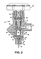
- the fluid flow path is illustrated vis-à-vis the inner components.
- the vacuum actuated check valve 26 is disposed in port body 29 of single port cylinder valve head 14. Following then the path of the boron trifluoride gas out of head valve 14, the gas first enters valve inlet 30 through internal flow restrictor tube 20.
- the port body of head valve 14 contains the vacuum actuated check valve 26. Entering gas first contacts valve element in the form of poppet 32.
- a spring 34 biases poppet valve 32 against a valve seat 36 to create a closed condition along the gas flow path.
- the top of poppet valve 32 may retain a resilient washer or other sealing element to maintain a positive seal across valve seat 36.
- Spring 34 normally presses poppet valve 32 against valve seat 36 until the bellows 38 expand to displace a contact plate 40.
- Contact plate 40 acts on a control pin 42 that pushes poppet 32 away from valve seat 36. Boron trifluoride gas may then flow through pin passage 44 around pin 42 and into a housing 54 that accommodates the bellows 38.
- Bellows chamber 50 consists of a bellows guide 48 that defines an internal pressure chamber having an outer sleeve/housing 54 that surrounds the exterior of the bellows chamber; and a bottom guide plate 56. Sealing contact at the upper end of the bellows with bellows guide 48, and at the lower end of the bellows with contact plate 40, isolates the bellows from pressure within vacuum actuated check valve 26 and the gas flow path in general.
- the internal part of bellows chamber 50 i.e., the pressure chamber
- the internal part of bellows chamber 50 is typically sealed at atmospheric pressure such that a reduction in pressure in the housing surrounding bellows chamber 50 causes the gases in bellows chamber 50 to expand bellows and urge contact plate 40 downward against pin 42.
- Bellows guide 48 retains outer sleeve 54 about its outer edge. Outer sleeve 54 positions with guide plate 56. Together, bellows guide 48, outer sleeve 54 and guide plate 56 protectively enclose bellows chamber 50. Pin 42 passes through a central hole in the guide plate 56 to maintain its alignment with contact plate 40.
- Threaded bushing 62 clamps a multi-layer metallic diaphragm 64 to port body 29 thereby forming a positive seal against fluid leaking past the valve stem 66.
- Handle 28 operating in conjunction with threaded valve stem 66, forces piston 68 via friction pad 70 onto diaphragm 64 to move the main valve plunger 72 down against the resisting force of spring 74. Downward movement of plunger 72 forces a elastomer sealing element 76, retained by nut 78, to create a seal at surfaces 60.
- Backing valve stem 66 away from diaphragm 64 allows spring 74 to force valve plunger 72 up, thereby separating the sealing surfaces 60 and permitting gas to flow through port 58. Once past sealing surfaces 60 boron trifluoride gas flows from a chamber 80 through conduit 82 and to the user port 18.
- This check valve 26 can be set to reliably prevent opening of the poppet 32 until pressure within the bellow housing drops to a vacuum condition. This condition is usually equal to 1.01 bar ( 760 torr ) or less. With this setting of the vacuum actuated check valve, turning handle 28 in a counter clockwise direction so as to retract valve plunger 70, would not result in a dispensation of boron trifluoride from the cylinder. Since the typical end-user's apparatus operates at pressure less than 0.133 bar ( 100 torr ) , dispensing boron trifluoride at a vacuum, and particularly at pressures of 0.667 bar ( 500 torr ) of less, has several distinct advantages.
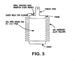
- the bellows chamber is charged with an inert gas, such as argon, to a pressure ranging from about 1.01 to about 3.45 bar ( about 14.7 psia to about 50 psia ) , preferably about 1.01 to about 2.41 bar ( about 14.7 psia to 35 psia ) and most preferably to about 2.03 bar ( 29.5 psia ) .
- an inert gas such as argon
- the bellows materials are selected from the group consisting of age hardened steel alloys, age hardened nickel based alloys (e.g., inconel) and copper beryllium alloys. While the foregoing are preferred materials, it will be understood by those skilled in the art that other materials having similar physical properties can be employed.
- the operation of the vacuum actuated check valve is based on a repeatable extension of the bellows as it senses sub-atmospheric pressures.
- the operation of the bellows over the length of its service life is critical (i.e. extension/contraction repeatability in response to a pressure condition).
- Bellows fabricated from cold worked materials such as austenitic stainless steels (utilized in the related art) have the potential to exhibit instability in terms of overall length change.
- Bellows length degradation or compression set is a characteristic of spring elements (i.e., bellows and helical springs, in which residual stresses are imparted during their forming process).
- the optimum class of materials for fabricating bellows elements with high resistance to compression set (or length degradation) and long term repeatability are age or precipitation hardened alloys, such as the ones discussed above.
- the age hardened alloys are preferred candidate materials since bellows chambers formed from this class of materials exhibit superior corrosion resistance and mechanical properties for the desired thrust forces.
- An additional benefit conferred by manufacturing the bellows with age hardened materials is the elimination of a bellows conditioning procedure. Specifically, in the related art a bellows conditioning procedure was developed and implemented prior to assembly of the bellows chamber into the system. This labor intensive procedure is no longer required as a result of utilizing the age hardened materials of the present invention.
- high pressure cylinder 12 can be filled to a capacity up to three times higher than cylinders currently utilized for ion implantation, without changing the dimensions of the cylinder.
- the current 2.27 liter cylinders with the bellows chamber of the present invention can be filled to a capacity of 1000 grams (at 86.16 bar (1235 psig ) ) versus 335 grams (at 42.4 bar ( 600 psig ) ) and 3180 grams versus 1065 grams for 6.33 liter cylinders currently employed.
- a restricted flow passage 20 can be placed along the flow path, upstream of the vacuum actuated check valve 26 to restrict the flow of gas in the unlikely event that the check valve fails in an open position, or otherwise valve head 14 having the check valve therein is sheared.
- One such restrictor in the form of, a capillary offers the most flexibility and reliability as a flow restrictor. Whether provided by single or multiple small diameter bores or tightly packed materials, suitable restrictors of this type will desirably limit the transport of gas phase fluids to very low rates.
- a single bore capillary can limit atmospheric boron trifluoride release to less than about 35 cm 3 /min ( sccm ) of boron trifluoride at a cylinder pressure of 83.75 bar ( 1200 psig ) and temperature of 20°C ( 68°F )
- a seven bore capillary can limit the flow rate to about 245 cm 3 /min ( sccm ) at similar conditions.
- the capillary tube provides the only exit from cylinder 12, and it can be in a winding formation and ordinarily has an internal diameter of less than 0.02 millimeters (0.001 inch).
- a metal tube 84 typically constructed from stainless steel, protectively surrounds a glass tube 86.
- the inside of diameter tube 86 holds a hexagon arrangement of 6 solid glass rods 86 about a central glass rod 90 and wherein all of the rods have about the same diameter.
- the spaces 92 between the rods 88 and rod 90 and between the rods 88 and the inside of tube 86 provide flow areas of capillary size for metering gas through the internal flow restrictor 20.
- Shrinking glass tube over the glass rods 88 and 90 provides a rigid tube and rod assembly.
- Metal tube 84 adds further rigidity and durability when optionally shrunk around glass rods 88 and 90 to provide a reinforced unit. With the optional reinforcement of metal tube 84, fracture of the glass rods or their surrounding glass tube would leave the function of the restricted flow path through the capillary structure substantially unchanged.
- the downward force in pounds produced by an actuation pressure of 0.40 bar ( 300 torr (5.8 psia) ) is the differential of the its internal pressure ( 1.01 bar ( 14.7 psia ) ) and the actuation pressure ( 0.40 bar ( 5.8 psia ) ) multiplied by the MEA ( 1.53 cm 2 ( 0.237 in 2 ) ) .
- actuation pressure 0.40 bar ( 5.8 psia )
- the bellows thrust force has been increased by modifying the bellows parameters so as to utilize conventional cylinder port openings, to in turn accommodate a substantial higher BF 3 capacity in the storage and delivery system.
- the bellows assembly configuration for the high capacity BF 3 design is shown in Figure 3 .
- the significant changes are the bellows material of construction and the annulus fill pressure.
- the precipitation or age hardened alloys have the best combination of properties for manufacture and operation of bellows, bordon tubes, springs, etc. They acquire their elastic properties as a result of heat treatment in contradistinction to austenitic stainless steels.
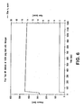
- the vacuum actuated check valve of the present invention therein was installed in a gas storage and delivery system and a flow test was conducted. Nitrogen gas was provided into the system so that the inlet pressure onto the vacuum actuated check valve was 85.82 bar ( 1230 psig ) . The flow test was conducted over a two and a half hour period of time. A pressure transducer connected downstream of the use-port measured sub-atmospheric actuation pressures as the MFC controlled the flow rates to 2 cm 3 /min ( sccm ) .
- the vacuum actuation pressure for the check valve with a cylinder fill pressure of 85,82 bar ( 1230 psig ) was between 0.560 and 0.587 bar ( 420 and 440 torr ) .
Landscapes
- Engineering & Computer Science (AREA)
- General Engineering & Computer Science (AREA)
- Mechanical Engineering (AREA)
- Physics & Mathematics (AREA)
- Automation & Control Theory (AREA)
- General Physics & Mathematics (AREA)
- Fluid Mechanics (AREA)
- Filling Or Discharging Of Gas Storage Vessels (AREA)
- Safety Valves (AREA)
- Details Of Valves (AREA)
- Supplying Of Containers To The Packaging Station (AREA)
- Pipeline Systems (AREA)
- Fluid-Pressure Circuits (AREA)
- Fluid-Driven Valves (AREA)
Claims (10)
- System zum Steuern der Ausgabe von unter Druck stehenden Fluiden aus dem Auslass eines unter Druck stehenden Tanks, welcher Hydrid- oder Halogenverbindungen enthält, mit:einem Tank (12) zum Halten eines unter Druck stehenden Fluids in einer gasförmigen oder teilweise gasförmigen Phase;einem Anschlusskörper (29), der mit dem Auslass eines unter Druck stehenden Tanks in Verbindung steht und einen Fluidausgabeweg (30, 44, 82) bestimmt;ein in dem Anschlusskörper oder stromauf des Anschlusskörpers angebrachtes Ventilelement (26), welches vorgesehen ist, um sich zwischen einer Dichtstellung, welche Fluidstrom durch den Fluidausgabeweg blockiert, und einer Offenstellung, welche Fluidstrom entlang des Fluidausgabewegs erlaubt, zu bewegen;einer Balgkammer (50), die innerhalb eines Gehäuses stromab des Ventilelements angeordnet ist, wobei die Balgkammer mit einem Teil des Fluidausgabewegs stromab des Ventilelements in Verbindung steht, um das Ventilelement in die Offenstellung zu bewegen, wenn die Verbindung mit dem Fluidausgabeweg eine Vakuumbedingung innerhalb des Gehäuses erzeugt, dadurch gekennzeichnet, dassdie Balgkammer (50) auf einen Druck im Bereich von mehr als 1,01 bis 3,45 bar (14,7 psia bis 50 psia) dichtend aufgedrückt ist und einen Balg (38) aufweist, der aus einem aus der aus bei normaler Temperatur ausgehärteten Stahllegierungen, bei normaler Temperatur ausgehärteten nickelbasierenden Legierungen und Kupferberyllium-Legierungen bestehenden Gruppe ausgewählten Material gefertigt ist.
- System gemäß Anspruch 1, wobei das Ventilelement (26) ein Sitzventil (32, 34 36, 42) aufweist und eine Ausdehnung des Balgs (38) den Stift (43) veranlasst, den Ventilteller in eine Offenstellung zu verlagern.
- System gemäß Anspruch 1, wobei der Tank (12) ein gasförmiges Fluid bei einem Druck im Bereich von 42,4 bis 104,4 bar (600 psig bis 1500 psig) bei Bedingungen maximaler Kapazität enthält.
- System gemäß Anspruch 1, wobei die Balgkammer (50) bei einem Druck von etwa 1,72 bar (25 psia) abgedichtet ist.
- System gemäß Anspruch 1, wobei sich bei dem Balg (38) um ein bei normaler Temperatur ausgehärtetes Inconelmaterial handelt.
- System gemäß Anspruch 1, wobei der Tank (12) ferner eine Drosselung (50) entlang mindestens eines Teils des Strömungswegs aufweist, welche den Strom des in dem Tank enthaltenen Gases auf weniger als 35 cm3/min (sccm) bei Atmosphärenbedingungen begrenzt.
- System gemäß Anspruch 6, wobei es sich bei der Drosselung (20) um mindestens eine Leitung (86, 88, 90, 92) handelt.
- System gemäß Anspruch 7, wobei es sich bei der mindestens einen Leitung (86, 88, 90, 92) um eine Kapillarröhre mit einem Innendurchmesser handelt, der 0,22 mm nicht übersteigt.
- System gemäß Anspruch 1, wobei es sich bei dem Tank um einen Zylinder mit einer Zylinderöffnung handelt; der Anschlusskörper für einen dichtenden Eingriff mit der Zylinderöffnung ausgelegt ist; ein Fluideinlassanschluss durch den Anschlusskörper festgelegt ist und im Inneren des Zylinders angeordnet ist; ein Fluidauslassanschluss durch den Anschlusskörper festgelegt ist und außerhalb des Zylinders angeordnet ist; sich der von dem Anschlusskörper festgelegte Fluidausgabeweg zwischen dem Fluideinlassanschluss und dem Fluidauslassanschluss erstreckt; ein Absperrventil vorgesehen ist, um den Fluidstrom entlang des Fluidausgabewegs zu steuern;
das Ventilelement in die Dichtstellung vorgespannt ist;
die Balgkammer in einem vakuumbetätigten Rückschlagventil enthalten ist; und
die Balgkammer einen Abschnitt, der bezüglich des Körpers des vakuumbetätigten Rückschlagventils fest abgebracht ist, sowie einen anderen Abschnitt aufweist, der in Wirkverbindung mit dem Ventilelement steht, wenn ein relativer Druck zwischen dem Inneren und dem Äußeren des Balgs den Balg ausdehnt und das Ventilelement in eine offene Stellung vorspannt, um einen Fluidstrom entlang des Fluidausgabewegs zu erlauben. - Balganordnung eines vakuumbetätigten Rückschlagventils, mit:einer Balgkammer (50), die innerhalb des Gehäuses (29) des vakuumbetätigten Rückschlagventils angeordnet ist, dadurch gekennzeichnet, dass die Balgkammer auf einen Druck im Bereich von mehr als 1,01 bis 3,45 bar (14,7 psia bis 50 psia) aufgedrückt und abgedichtet ist, wobei der Balg (38) aus einem aus der aus bei normaler Temperatur ausgehärteten Stahllegierungen, bei normaler Temperatur ausgehärteten nickelbasierenden Legierungen und Kupferberyllium-Legierungen bestehenden Gruppe ausgewählten Material gefertigt ist; und wobei der Balg auf eine Vakuumbedingung an der Außenseite der Balgkammer anspricht, um den Balg mit einer Schubkraft von mindestens 17,8 Newton (4 lbf) auszudehnen.
Applications Claiming Priority (2)
| Application Number | Priority Date | Filing Date | Title |
|---|---|---|---|
| US11/635,875 US7708028B2 (en) | 2006-12-08 | 2006-12-08 | Fail-safe vacuum actuated valve for high pressure delivery systems |
| PCT/US2007/086959 WO2008073882A1 (en) | 2006-12-08 | 2007-12-10 | Fail-safe vacuum actuated valve for high pressure delivery systems |
Publications (2)
| Publication Number | Publication Date |
|---|---|
| EP2095010A1 EP2095010A1 (de) | 2009-09-02 |
| EP2095010B1 true EP2095010B1 (de) | 2010-10-13 |
Family
ID=39276087
Family Applications (1)
| Application Number | Title | Priority Date | Filing Date |
|---|---|---|---|
| EP20070855050 Not-in-force EP2095010B1 (de) | 2006-12-08 | 2007-12-10 | Ausfallsicheres, durch unterdruck betätigtes ventil für hochdruckzufuhrsysteme |
Country Status (10)
| Country | Link |
|---|---|
| US (1) | US7708028B2 (de) |
| EP (1) | EP2095010B1 (de) |
| JP (1) | JP2010512491A (de) |
| KR (1) | KR20090096696A (de) |
| CN (1) | CN101225924B (de) |
| AT (1) | ATE484709T1 (de) |
| DE (1) | DE602007009866D1 (de) |
| IL (1) | IL198877A (de) |
| TW (1) | TWI410574B (de) |
| WO (1) | WO2008073882A1 (de) |
Families Citing this family (32)
| Publication number | Priority date | Publication date | Assignee | Title |
|---|---|---|---|---|
| US7905247B2 (en) * | 2008-06-20 | 2011-03-15 | Praxair Technology, Inc. | Vacuum actuated valve for high capacity storage and delivery systems |
| US8020398B2 (en) * | 2008-10-02 | 2011-09-20 | Varian Semiconductor Equipment Associates, Inc. | Fluid delivery mechanism for vacuum wafer processing system |
| WO2011065927A1 (en) * | 2009-11-27 | 2011-06-03 | Adichai Mathurapojchanakul | Device of high pressure gas-bypass-check valve |
| US9109755B2 (en) | 2010-06-18 | 2015-08-18 | Entegris, Inc. | Endpoint determination for capillary-assisted flow control |
| FR2979687B1 (fr) * | 2011-09-07 | 2013-09-27 | Air Liquide | Ensemble de connexion a un reservoir de fluide sous pression et reservoir comprenant un tel ensemble de connexion |
| US20130146166A1 (en) * | 2011-12-07 | 2013-06-13 | Serge Campeau | Auto shutoff device |
| US8740224B2 (en) | 2012-02-28 | 2014-06-03 | General Electric Company | Seal assembly for a turbomachine |
| WO2013167937A1 (en) * | 2012-05-08 | 2013-11-14 | L'air Liquide Societe, Anonyme Pour L'etude Et L'exploitation Des Procedes Georges Claude | Safety design for medical oxygen supply valvehead |
| EP2867565B1 (de) | 2012-06-28 | 2019-05-08 | Saint-Gobain Performance Plastics Corporation | Polymerbalgfeder |
| KR102373840B1 (ko) | 2012-09-21 | 2022-03-11 | 엔테그리스, 아이엔씨. | 압력 조절식 유체 보관 및 운반 용기의 스파이크 압력 방지 관리 |
| US8883620B1 (en) | 2013-04-24 | 2014-11-11 | Praxair Technology, Inc. | Methods for using isotopically enriched levels of dopant gas compositions in an ion implantation process |
| KR101685320B1 (ko) | 2013-05-02 | 2016-12-09 | 프랙스에어 테크놀로지, 인코포레이티드 | 농축 셀레늄 이온 주입을 위한 공급 소스 및 방법 |
| TWI580616B (zh) * | 2013-05-08 | 2017-05-01 | 友麗股份有限公司 | 旋轉式調節壓力桶 |
| GB201309046D0 (en) * | 2013-05-20 | 2013-07-03 | Linde Ag | A pressurised fluid container |
| US9165773B2 (en) | 2013-05-28 | 2015-10-20 | Praxair Technology, Inc. | Aluminum dopant compositions, delivery package and method of use |
| US9570271B2 (en) | 2014-03-03 | 2017-02-14 | Praxair Technology, Inc. | Boron-containing dopant compositions, systems and methods of use thereof for improving ion beam current and performance during boron ion implantation |
| CN103953769B (zh) * | 2014-03-28 | 2016-04-20 | 党新洲 | 一种减压阀 |
| US9909670B2 (en) | 2015-03-04 | 2018-03-06 | Praxair Technology, Inc. | Modified vacuum actuated valve assembly and sealing mechanism for improved flow stability for fluids sub-atmospherically dispensed from storage and delivery systems |
| WO2016183221A1 (en) * | 2015-05-12 | 2016-11-17 | Entegris, Inc. | Valve assemblies and fluid storage and dispensing packages comprising same |
| EP3188214A1 (de) | 2015-12-29 | 2017-07-05 | Praxair Technology, Inc. | Boronhaltige dotiermittelzusammensetzungen, systeme und verfahren zur verwendung davon zur verbesserung eines ionenstrahlstroms und der leistung während einer boronionenimplantation |
| US10221201B2 (en) * | 2015-12-31 | 2019-03-05 | Praxair Technology, Inc. | Tin-containing dopant compositions, systems and methods for use in ION implantation systems |
| US20170294289A1 (en) | 2016-04-11 | 2017-10-12 | Aaron Reinicker | Boron compositions suitable for ion implantation to produce a boron-containing ion beam current |
| US11098402B2 (en) | 2017-08-22 | 2021-08-24 | Praxair Technology, Inc. | Storage and delivery of antimony-containing materials to an ion implanter |
| US10597773B2 (en) | 2017-08-22 | 2020-03-24 | Praxair Technology, Inc. | Antimony-containing materials for ion implantation |
| WO2019212687A1 (en) | 2018-05-04 | 2019-11-07 | Entegris, Inc. | Regulator stability in a pressure regulated storage vessel |
| CN112325146A (zh) * | 2019-08-05 | 2021-02-05 | 古丰愿 | 负压供气钢瓶 |
| CN110748784B (zh) * | 2019-11-08 | 2021-04-13 | 江苏德翔化工机械有限公司 | 一种可调节容量的储气罐 |
| US11577217B2 (en) | 2019-12-12 | 2023-02-14 | Praxair Technology, Inc. | Dopant fluid storage and dispensing systems utilizing high performance, structurally modified particulate carbon adsorbents |
| LU101650B1 (en) * | 2020-02-25 | 2021-08-25 | Luxembourg Patent Co | Closing member of a gas valve for very high pressure |
| JP2023520933A (ja) | 2020-05-11 | 2023-05-22 | プラクスエア・テクノロジー・インコーポレイテッド | イオン注入器へのアンチモン含有材料の貯蔵及び送達 |
| US12085175B2 (en) * | 2020-10-15 | 2024-09-10 | North Atlantic Imports, Llc | Valve structure for propane tank and method thereof |
| LU102229B1 (en) * | 2020-11-25 | 2022-05-30 | Rotarex S A | Cylindrical sub-atmospheric pressure regulating device for insertion into a gas cylinder |
Family Cites Families (23)
| Publication number | Priority date | Publication date | Assignee | Title |
|---|---|---|---|---|
| US3245583A (en) | 1964-02-11 | 1966-04-12 | Reynolds Metals Co | Gas charging and liquid dispensing apparatus and method |
| US3709242A (en) | 1970-12-04 | 1973-01-09 | Beckman Instruments Inc | Pressure regulator |
| US4134449A (en) * | 1976-12-02 | 1979-01-16 | Hague International | Bellows sealing arrangement |
| US4143672A (en) * | 1977-06-21 | 1979-03-13 | Apv Corporation | Anti-pollution valve for use with shipboard storage tanks |
| US4222713A (en) * | 1979-05-29 | 1980-09-16 | Caterpillar Tractor Co. | Temperature responsive fuel compensator |
| US4793379A (en) | 1982-07-16 | 1988-12-27 | Eidsmore Paul G | Supply cylinder shut-off and flow control valve |
| DK0522583T3 (da) * | 1991-07-12 | 1995-09-25 | Praxair Technology Inc | Pakningselement til roterende kontakt coatet med en chromcarbid-ældningshærdbar nikkelbaseret legeri ng |
| GB9220975D0 (en) | 1992-10-06 | 1992-11-18 | Air Prod & Chem | Apparatus for supplying high purity gas |
| US5303734A (en) | 1993-02-01 | 1994-04-19 | Eidsmore Paul G | Pressure regulator |
| JP3114009B2 (ja) * | 1995-10-24 | 2000-12-04 | 株式会社エスアイアイ・マイクロパーツ | 高耐食性ベローズ |
| JPH11111644A (ja) * | 1997-09-30 | 1999-04-23 | Japan Pionics Co Ltd | 気化供給装置 |
| US6007609A (en) | 1997-12-18 | 1999-12-28 | Uop Llc | Pressurized container with restrictor tube having multiple capillary passages |
| US5937895A (en) | 1998-04-17 | 1999-08-17 | Uop Llc | Fail-safe delivery valve for pressurized tanks |
| US6045115A (en) | 1998-04-17 | 2000-04-04 | Uop Llc | Fail-safe delivery arrangement for pressurized containers |
| US6101816A (en) | 1998-04-28 | 2000-08-15 | Advanced Technology Materials, Inc. | Fluid storage and dispensing system |
| RU2164188C2 (ru) * | 1999-02-04 | 2001-03-20 | Открытое акционерное общество НПО Энергомаш им.акад. В.П. Глушко | Способ изготовления многослойных тонкостенных сильфонов |
| JP4608041B2 (ja) * | 1999-08-03 | 2011-01-05 | プラクスエア・テクノロジー・インコーポレイテッド | 加圧タンク用フェイル−セーフ送出し弁 |
| US6360546B1 (en) | 2000-08-10 | 2002-03-26 | Advanced Technology Materials, Inc. | Fluid storage and dispensing system featuring externally adjustable regulator assembly for high flow dispensing |
| JP2003166700A (ja) | 2001-11-30 | 2003-06-13 | Nippon Sanso Corp | 減圧機能付き容器弁 |
| US6857447B2 (en) | 2002-06-10 | 2005-02-22 | Advanced Technology Materials, Inc. | Pressure-based gas delivery system and method for reducing risks associated with storage and delivery of high pressure gases |
| US6959724B2 (en) * | 2002-07-01 | 2005-11-01 | Praxair Technology, Inc. | Multiple regulator vacuum delivery valve assembly |
| AU2003302879A1 (en) | 2002-12-10 | 2004-06-30 | Koninklijke Philips Electronics N.V. | A wearable device for bioelectrical interaction with motion artifact correction means |
| US6868869B2 (en) | 2003-02-19 | 2005-03-22 | Advanced Technology Materials, Inc. | Sub-atmospheric pressure delivery of liquids, solids and low vapor pressure gases |
-
2006
- 2006-12-08 US US11/635,875 patent/US7708028B2/en not_active Expired - Fee Related
-
2007
- 2007-11-19 TW TW96143701A patent/TWI410574B/zh not_active IP Right Cessation
- 2007-12-10 KR KR1020097011589A patent/KR20090096696A/ko not_active Ceased
- 2007-12-10 AT AT07855050T patent/ATE484709T1/de not_active IP Right Cessation
- 2007-12-10 CN CN2007101995106A patent/CN101225924B/zh not_active Expired - Fee Related
- 2007-12-10 JP JP2009540514A patent/JP2010512491A/ja active Pending
- 2007-12-10 WO PCT/US2007/086959 patent/WO2008073882A1/en not_active Ceased
- 2007-12-10 EP EP20070855050 patent/EP2095010B1/de not_active Not-in-force
- 2007-12-10 DE DE200760009866 patent/DE602007009866D1/de active Active
-
2009
- 2009-05-21 IL IL198877A patent/IL198877A/en active IP Right Grant
Also Published As
| Publication number | Publication date |
|---|---|
| WO2008073882A1 (en) | 2008-06-19 |
| KR20090096696A (ko) | 2009-09-14 |
| US7708028B2 (en) | 2010-05-04 |
| TW200835876A (en) | 2008-09-01 |
| IL198877A0 (en) | 2010-02-17 |
| ATE484709T1 (de) | 2010-10-15 |
| TWI410574B (zh) | 2013-10-01 |
| CN101225924B (zh) | 2010-04-14 |
| DE602007009866D1 (de) | 2010-11-25 |
| IL198877A (en) | 2012-10-31 |
| EP2095010A1 (de) | 2009-09-02 |
| US20080135104A1 (en) | 2008-06-12 |
| JP2010512491A (ja) | 2010-04-22 |
| CN101225924A (zh) | 2008-07-23 |
Similar Documents
| Publication | Publication Date | Title |
|---|---|---|
| US7708028B2 (en) | Fail-safe vacuum actuated valve for high pressure delivery systems | |
| US7905247B2 (en) | Vacuum actuated valve for high capacity storage and delivery systems | |
| EP1534991B1 (de) | Vakuumzufuhrventilanordnung mit mehrfachregler | |
| EP3265420B1 (de) | Modifizierte vakuumbetätigte ventilbaugruppe und versiegelungsmechanismus zur verbesserten strömungsstabilität für fluide, die subatmosphärisch aus aufbewahrungs- und ausgabesystemen abgegeben werden | |
| US6045115A (en) | Fail-safe delivery arrangement for pressurized containers | |
| EP1328756B1 (de) | Gasspeicher- und verteilsystem mit einem ein fluid enthaltenden gefäss, welches einen in situ einstellbaren regler enthält | |
| US20180180225A1 (en) | Anti-spike pressure management of pressure-regulated fluid storage and delivery vessels | |
| CN201273451Y (zh) | 用于控制加压流体的系统、气瓶和阀组件与波纹管组件 | |
| US20040000339A1 (en) | Multiple dispensing check valve delivery system | |
| EP1074786B1 (de) | Sicherheitsventil für Druckbehälter | |
| US20130146166A1 (en) | Auto shutoff device |
Legal Events
| Date | Code | Title | Description |
|---|---|---|---|
| PUAI | Public reference made under article 153(3) epc to a published international application that has entered the european phase |
Free format text: ORIGINAL CODE: 0009012 |
|
| 17P | Request for examination filed |
Effective date: 20090619 |
|
| AK | Designated contracting states |
Kind code of ref document: A1 Designated state(s): AT BE BG CH CY CZ DE DK EE ES FI FR GB GR HU IE IS IT LI LT LU LV MC MT NL PL PT RO SE SI SK TR |
|
| 17Q | First examination report despatched |
Effective date: 20090925 |
|
| DAX | Request for extension of the european patent (deleted) | ||
| GRAP | Despatch of communication of intention to grant a patent |
Free format text: ORIGINAL CODE: EPIDOSNIGR1 |
|
| GRAS | Grant fee paid |
Free format text: ORIGINAL CODE: EPIDOSNIGR3 |
|
| GRAA | (expected) grant |
Free format text: ORIGINAL CODE: 0009210 |
|
| AK | Designated contracting states |
Kind code of ref document: B1 Designated state(s): AT BE BG CH CY CZ DE DK EE ES FI FR GB GR HU IE IS IT LI LT LU LV MC MT NL PL PT RO SE SI SK TR |
|
| REG | Reference to a national code |
Ref country code: GB Ref legal event code: FG4D |
|
| REG | Reference to a national code |
Ref country code: CH Ref legal event code: EP |
|
| REG | Reference to a national code |
Ref country code: IE Ref legal event code: FG4D |
|
| REF | Corresponds to: |
Ref document number: 602007009866 Country of ref document: DE Date of ref document: 20101125 Kind code of ref document: P |
|
| REG | Reference to a national code |
Ref country code: NL Ref legal event code: VDEP Effective date: 20101013 |
|
| LTIE | Lt: invalidation of european patent or patent extension |
Effective date: 20101013 |
|
| PG25 | Lapsed in a contracting state [announced via postgrant information from national office to epo] |
Ref country code: LT Free format text: LAPSE BECAUSE OF FAILURE TO SUBMIT A TRANSLATION OF THE DESCRIPTION OR TO PAY THE FEE WITHIN THE PRESCRIBED TIME-LIMIT Effective date: 20101013 |
|
| PG25 | Lapsed in a contracting state [announced via postgrant information from national office to epo] |
Ref country code: PT Free format text: LAPSE BECAUSE OF FAILURE TO SUBMIT A TRANSLATION OF THE DESCRIPTION OR TO PAY THE FEE WITHIN THE PRESCRIBED TIME-LIMIT Effective date: 20110214 Ref country code: NL Free format text: LAPSE BECAUSE OF FAILURE TO SUBMIT A TRANSLATION OF THE DESCRIPTION OR TO PAY THE FEE WITHIN THE PRESCRIBED TIME-LIMIT Effective date: 20101013 Ref country code: AT Free format text: LAPSE BECAUSE OF FAILURE TO SUBMIT A TRANSLATION OF THE DESCRIPTION OR TO PAY THE FEE WITHIN THE PRESCRIBED TIME-LIMIT Effective date: 20101013 Ref country code: LV Free format text: LAPSE BECAUSE OF FAILURE TO SUBMIT A TRANSLATION OF THE DESCRIPTION OR TO PAY THE FEE WITHIN THE PRESCRIBED TIME-LIMIT Effective date: 20101013 Ref country code: IS Free format text: LAPSE BECAUSE OF FAILURE TO SUBMIT A TRANSLATION OF THE DESCRIPTION OR TO PAY THE FEE WITHIN THE PRESCRIBED TIME-LIMIT Effective date: 20110213 Ref country code: FI Free format text: LAPSE BECAUSE OF FAILURE TO SUBMIT A TRANSLATION OF THE DESCRIPTION OR TO PAY THE FEE WITHIN THE PRESCRIBED TIME-LIMIT Effective date: 20101013 Ref country code: BG Free format text: LAPSE BECAUSE OF FAILURE TO SUBMIT A TRANSLATION OF THE DESCRIPTION OR TO PAY THE FEE WITHIN THE PRESCRIBED TIME-LIMIT Effective date: 20110113 Ref country code: SI Free format text: LAPSE BECAUSE OF FAILURE TO SUBMIT A TRANSLATION OF THE DESCRIPTION OR TO PAY THE FEE WITHIN THE PRESCRIBED TIME-LIMIT Effective date: 20101013 Ref country code: SE Free format text: LAPSE BECAUSE OF FAILURE TO SUBMIT A TRANSLATION OF THE DESCRIPTION OR TO PAY THE FEE WITHIN THE PRESCRIBED TIME-LIMIT Effective date: 20101013 |
|
| PG25 | Lapsed in a contracting state [announced via postgrant information from national office to epo] |
Ref country code: GR Free format text: LAPSE BECAUSE OF FAILURE TO SUBMIT A TRANSLATION OF THE DESCRIPTION OR TO PAY THE FEE WITHIN THE PRESCRIBED TIME-LIMIT Effective date: 20110114 |
|
| PG25 | Lapsed in a contracting state [announced via postgrant information from national office to epo] |
Ref country code: MC Free format text: LAPSE BECAUSE OF NON-PAYMENT OF DUE FEES Effective date: 20101231 Ref country code: EE Free format text: LAPSE BECAUSE OF FAILURE TO SUBMIT A TRANSLATION OF THE DESCRIPTION OR TO PAY THE FEE WITHIN THE PRESCRIBED TIME-LIMIT Effective date: 20101013 Ref country code: ES Free format text: LAPSE BECAUSE OF FAILURE TO SUBMIT A TRANSLATION OF THE DESCRIPTION OR TO PAY THE FEE WITHIN THE PRESCRIBED TIME-LIMIT Effective date: 20110124 Ref country code: CZ Free format text: LAPSE BECAUSE OF FAILURE TO SUBMIT A TRANSLATION OF THE DESCRIPTION OR TO PAY THE FEE WITHIN THE PRESCRIBED TIME-LIMIT Effective date: 20101013 |
|
| PLBE | No opposition filed within time limit |
Free format text: ORIGINAL CODE: 0009261 |
|
| STAA | Information on the status of an ep patent application or granted ep patent |
Free format text: STATUS: NO OPPOSITION FILED WITHIN TIME LIMIT |
|
| PG25 | Lapsed in a contracting state [announced via postgrant information from national office to epo] |
Ref country code: PL Free format text: LAPSE BECAUSE OF FAILURE TO SUBMIT A TRANSLATION OF THE DESCRIPTION OR TO PAY THE FEE WITHIN THE PRESCRIBED TIME-LIMIT Effective date: 20101013 Ref country code: DK Free format text: LAPSE BECAUSE OF FAILURE TO SUBMIT A TRANSLATION OF THE DESCRIPTION OR TO PAY THE FEE WITHIN THE PRESCRIBED TIME-LIMIT Effective date: 20101013 Ref country code: SK Free format text: LAPSE BECAUSE OF FAILURE TO SUBMIT A TRANSLATION OF THE DESCRIPTION OR TO PAY THE FEE WITHIN THE PRESCRIBED TIME-LIMIT Effective date: 20101013 Ref country code: RO Free format text: LAPSE BECAUSE OF FAILURE TO SUBMIT A TRANSLATION OF THE DESCRIPTION OR TO PAY THE FEE WITHIN THE PRESCRIBED TIME-LIMIT Effective date: 20101013 |
|
| 26N | No opposition filed |
Effective date: 20110714 |
|
| REG | Reference to a national code |
Ref country code: DE Ref legal event code: R097 Ref document number: 602007009866 Country of ref document: DE Effective date: 20110714 |
|
| PG25 | Lapsed in a contracting state [announced via postgrant information from national office to epo] |
Ref country code: IT Free format text: LAPSE BECAUSE OF NON-PAYMENT OF DUE FEES Effective date: 20101210 Ref country code: MT Free format text: LAPSE BECAUSE OF FAILURE TO SUBMIT A TRANSLATION OF THE DESCRIPTION OR TO PAY THE FEE WITHIN THE PRESCRIBED TIME-LIMIT Effective date: 20101013 |
|
| REG | Reference to a national code |
Ref country code: CH Ref legal event code: PL |
|
| GBPC | Gb: european patent ceased through non-payment of renewal fee |
Effective date: 20111210 |
|
| PG25 | Lapsed in a contracting state [announced via postgrant information from national office to epo] |
Ref country code: CY Free format text: LAPSE BECAUSE OF FAILURE TO SUBMIT A TRANSLATION OF THE DESCRIPTION OR TO PAY THE FEE WITHIN THE PRESCRIBED TIME-LIMIT Effective date: 20101013 |
|
| PG25 | Lapsed in a contracting state [announced via postgrant information from national office to epo] |
Ref country code: HU Free format text: LAPSE BECAUSE OF FAILURE TO SUBMIT A TRANSLATION OF THE DESCRIPTION OR TO PAY THE FEE WITHIN THE PRESCRIBED TIME-LIMIT Effective date: 20110414 Ref country code: LU Free format text: LAPSE BECAUSE OF NON-PAYMENT OF DUE FEES Effective date: 20101210 |
|
| PG25 | Lapsed in a contracting state [announced via postgrant information from national office to epo] |
Ref country code: CH Free format text: LAPSE BECAUSE OF NON-PAYMENT OF DUE FEES Effective date: 20111231 Ref country code: GB Free format text: LAPSE BECAUSE OF NON-PAYMENT OF DUE FEES Effective date: 20111210 Ref country code: TR Free format text: LAPSE BECAUSE OF FAILURE TO SUBMIT A TRANSLATION OF THE DESCRIPTION OR TO PAY THE FEE WITHIN THE PRESCRIBED TIME-LIMIT Effective date: 20101013 Ref country code: LI Free format text: LAPSE BECAUSE OF NON-PAYMENT OF DUE FEES Effective date: 20111231 |
|
| REG | Reference to a national code |
Ref country code: FR Ref legal event code: PLFP Year of fee payment: 9 |
|
| REG | Reference to a national code |
Ref country code: FR Ref legal event code: PLFP Year of fee payment: 10 |
|
| PG25 | Lapsed in a contracting state [announced via postgrant information from national office to epo] |
Ref country code: IT Free format text: LAPSE BECAUSE OF NON-PAYMENT OF DUE FEES Effective date: 20151210 |
|
| PG25 | Lapsed in a contracting state [announced via postgrant information from national office to epo] |
Ref country code: IT Free format text: LAPSE BECAUSE OF NON-PAYMENT OF DUE FEES Effective date: 20151210 |
|
| PGRI | Patent reinstated in contracting state [announced from national office to epo] |
Ref country code: IT Effective date: 20170710 |
|
| REG | Reference to a national code |
Ref country code: FR Ref legal event code: PLFP Year of fee payment: 11 |
|
| PGFP | Annual fee paid to national office [announced via postgrant information from national office to epo] |
Ref country code: IE Payment date: 20191121 Year of fee payment: 13 |
|
| PGFP | Annual fee paid to national office [announced via postgrant information from national office to epo] |
Ref country code: BE Payment date: 20191122 Year of fee payment: 13 |
|
| PGFP | Annual fee paid to national office [announced via postgrant information from national office to epo] |
Ref country code: FR Payment date: 20201120 Year of fee payment: 14 Ref country code: IT Payment date: 20201123 Year of fee payment: 14 Ref country code: DE Payment date: 20201119 Year of fee payment: 14 |
|
| REG | Reference to a national code |
Ref country code: BE Ref legal event code: MM Effective date: 20201231 |
|
| PG25 | Lapsed in a contracting state [announced via postgrant information from national office to epo] |
Ref country code: IE Free format text: LAPSE BECAUSE OF NON-PAYMENT OF DUE FEES Effective date: 20201210 |
|
| REG | Reference to a national code |
Ref country code: DE Ref legal event code: R119 Ref document number: 602007009866 Country of ref document: DE |
|
| PG25 | Lapsed in a contracting state [announced via postgrant information from national office to epo] |
Ref country code: BE Free format text: LAPSE BECAUSE OF NON-PAYMENT OF DUE FEES Effective date: 20201231 |
|
| PG25 | Lapsed in a contracting state [announced via postgrant information from national office to epo] |
Ref country code: DE Free format text: LAPSE BECAUSE OF NON-PAYMENT OF DUE FEES Effective date: 20220701 |
|
| PG25 | Lapsed in a contracting state [announced via postgrant information from national office to epo] |
Ref country code: FR Free format text: LAPSE BECAUSE OF NON-PAYMENT OF DUE FEES Effective date: 20211231 |
|
| PG25 | Lapsed in a contracting state [announced via postgrant information from national office to epo] |
Ref country code: IT Free format text: LAPSE BECAUSE OF NON-PAYMENT OF DUE FEES Effective date: 20211231 |