EP2095740A1 - Système de connexion d'éléments de structure - Google Patents
Système de connexion d'éléments de structure Download PDFInfo
- Publication number
- EP2095740A1 EP2095740A1 EP09002728A EP09002728A EP2095740A1 EP 2095740 A1 EP2095740 A1 EP 2095740A1 EP 09002728 A EP09002728 A EP 09002728A EP 09002728 A EP09002728 A EP 09002728A EP 2095740 A1 EP2095740 A1 EP 2095740A1
- Authority
- EP
- European Patent Office
- Prior art keywords
- sleeve
- aperture
- securing
- members
- structure members
- Prior art date
- Legal status (The legal status is an assumption and is not a legal conclusion. Google has not performed a legal analysis and makes no representation as to the accuracy of the status listed.)
- Withdrawn
Links
- 230000004308 accommodation Effects 0.000 claims abstract description 39
- 238000003780 insertion Methods 0.000 claims abstract description 8
- 230000037431 insertion Effects 0.000 claims abstract description 8
- 238000004891 communication Methods 0.000 claims abstract description 3
- 239000000463 material Substances 0.000 claims description 5
- 230000001419 dependent effect Effects 0.000 claims description 3
- 239000007787 solid Substances 0.000 claims description 3
- 239000011796 hollow space material Substances 0.000 claims description 2
- 238000010276 construction Methods 0.000 description 2
- 238000001746 injection moulding Methods 0.000 description 2
- 239000012815 thermoplastic material Substances 0.000 description 2
- 239000000853 adhesive Substances 0.000 description 1
- 230000001070 adhesive effect Effects 0.000 description 1
- XAGFODPZIPBFFR-UHFFFAOYSA-N aluminium Chemical compound [Al] XAGFODPZIPBFFR-UHFFFAOYSA-N 0.000 description 1
- 229910052782 aluminium Inorganic materials 0.000 description 1
- 239000004411 aluminium Substances 0.000 description 1
- 238000005452 bending Methods 0.000 description 1
- 230000009194 climbing Effects 0.000 description 1
- 238000001125 extrusion Methods 0.000 description 1
- 238000004519 manufacturing process Methods 0.000 description 1
- 230000013011 mating Effects 0.000 description 1
- 238000000034 method Methods 0.000 description 1
- 238000002360 preparation method Methods 0.000 description 1
Images


Classifications
-
- A—HUMAN NECESSITIES
- A47—FURNITURE; DOMESTIC ARTICLES OR APPLIANCES; COFFEE MILLS; SPICE MILLS; SUCTION CLEANERS IN GENERAL
- A47B—TABLES; DESKS; OFFICE FURNITURE; CABINETS; DRAWERS; GENERAL DETAILS OF FURNITURE
- A47B47/00—Cabinets, racks or shelf units, characterised by features related to dismountability or building-up from elements
Definitions
- the invention relates to a system for connecting structure members, in particular of structures such as furniture structures like tables, cabinets or chairs, to be used by man, in particular a system for connecting frame members of the structure concerned.
- the invention relates to a system for connecting structure members for playing structures such as climbing frames, playing houses and/or toys.
- the invention provides a system of a first and a second structure member, in particular frame members, and a connecting assembly for connecting said first and second structure members, wherein both said first and second structure members have a first side and a second side, wherein both said first and second structure members are provided with at least one first accommodation space for accommodating/receiving a portion of the connecting assembly, said accommodation space debouching in said first side through a first aperture, wherein said connecting assembly comprises a connecting sleeve having an axis and being adapted for accommodation in said first accommodation spaces in both said structure members and provided with first and second connecting portions, which are located at a distance from one another in sleeve axis direction, preferably are located at the opposite ends of said sleeve, and which can assume a connecting position in which they engage the first and second structure members, respectively, to prevent detachment of said structure members from each other, wherein the connecting assembly further comprises a securing device insertable in said connecting
- Such a system may allow a fast and easy, as well as a secure connection of the structure members with each other.
- the securing device engages both first and second connecting portions to secure them in their connecting position.
- the pin may have a length that is larger than the distance between the first and second connecting portions.
- the securing device may be formed in two separate parts, in particular halves, wherein the parts or halves are inserted one after the other into the connecting sleeve and abut one another axially.
- the first inserted part or halve can be pushed up to the correct position by the second inserted part or halve.
- said securing device is a single securing member, so that only one item has to be inserted into the sleeve.
- the securing member is a solid body.
- the single securing member can be a massive body.
- the single securing member is pin-shaped so as to facilitate insertion.
- said first and second connecting portions are radially movable with respect to said sleeve axis between a free position and the connecting position, wherein, preferably, the first and second portions are resiliently biased towards their connecting position, so that the insertion of the securing member is facilitated.
- said securing device is removably insertable in said connecting sleeve.
- the connecting sleeve can be removed also in order to disassemble the connection on purpose. This is made particularly easy if both structure members have a second side provided with said second aperture for passage of said securing device, wherein said first and second apertures preferably are substantially aligned with one another. The securing member can then be removed in a direction corresponding to the direction of insertion or in counter direction, depending on what the user prefers.
- the securing member in case the securing member has been pushed into the sleeve into its securing position, the securing member need not to be pulled back for disassembling, which might be difficult for lack of grip, but can be pushed further in the same direction or be pushed back in opposite direction, for instance by means of a screwdriver.
- the accommodation spaces can be formed by the material of the structure members.
- a system according to the invention comprises, from another aspect, a further item.
- said first accommodation space in at least one of said structure members may be at least in part formed by an insert dimensioned to be included, preferably removably, in said structure member.
- the use of the insert renders the firmness of the connection less dependent on the material and the shape of the structure members.
- the materials used for the insert and for the sleeve can be easily adjusted to one another.
- the structure members may be fabricated in a simple manner.
- said first and/or second structure member form(s) a hollow space for receiving the insert in a snugly fitting manner.
- the first accommodation spaces may be provided with first stop edges, wherein said first and second connecting potions are provided with second stop edges for engaging behind the first stop edges.
- first and/or second structure member is provided with a series of first apertures in its first side, preferably regularly spaced apart from one another. The person assembling the system can then choose the most appropriate location for the connection.
- said insert is movable, preferably slidable, inside said structure member to be brought in line with a selected one of said first apertures. This facilitates the preparation for the connection or the production of versatile structure members.
- said first and/or second structure member is provided with at least one further side, such as said second side, provided with at least one further aperture, which is preferably similar to the first aperture, and at least one further accommodation space debouching in said further side through said further aperture, wherein said first and further apertures each have an axis, said axis of said further aperture and said axis of said first aperture preferably being in one plane.
- Said further side may be provided with a series of further apertures, preferably regularly spaced apart from one another, preferably with a spacing corresponding to the spacing between the first apertures.
- the structure member can then be used in many ways.
- said insert forms both said first and said further accommodation spaces.
- the insert forms a plurality of said accommodation spaces, oriented in different directions, preferably including two or three orthogonal directions.
- the securing member can be inserted through the further side.
- said first and/or said second structure member being elongated and, preferably, having a polygonal cross-section.
- the connecting sleeve and the accommodation spaces have mating edges that are non-circular, in particular polygonal, so that their mutual rotation is prevented and the mutual orientation of the two structure members is fixed.
- the invention provides a system of a first and a second structure member, in particular frame member, and a connecting assembly for connecting said first and second structure member, wherein both said first and second structure members have a first side and a second side, wherein both said first and second structure members are provided with at least one first accommodation space for accommodating a portion of the connecting assembly, said accommodation space debouching in said first side through a first aperture, wherein said connecting assembly comprises a connecting sleeve adapted for accommodation in said first accommodation spaces in both said structure members and being provided with first and second connecting portions which can assume a connecting position in which they engage the first and second structure members, respectively, to prevent detachment of said structure members from each other, and a single securing member insertable in said connecting sleeve to a securing position for securing the first and second connecting portions in their connecting position, wherein the first accommodation space of at least one of both structure members and a second aperture in the second side of the same structure member form part of an internal passage for the securing member
- said connecting assembly connects the first and second structure member with their first sides abutting one another.
- the invention provides a structure, in particular a utility structure, such as a furniture structure, comprising one or more systems according to the invention.
- the system according to the invention may be designed to be assembled without any special tool.
- FIG 1A a connecting sleeve 3 is shown, made from a thermoplastic material by injection moulding.
- the sleeve 3 has an axis S and is symmetrical with respect to a central flange 17 forming a connection between two sleeve halves 15a,b.
- Each sleeve half 15a,b comprises four lips 18a,b bounding a passage 29 that extends through the flange 17.
- the lips 18a,b are resiliently bendable in direction E and are provided with stop edges 19a,b at their outer ends.
- the distance between the stop edges 19a,b is L1 and the length of the sleeve halves 15a,b is L2.
- the diameter of the flange 17 is D1 and the outer diameter of the sleeve halves 15a,b is D2, at locations between the stop edges 19a,b and the flange 17.
- a securing pin 5 is shown, which is dimensionally stable (retains its shape) and made from a rigid material and having a cylindrical outer surface 20 with axis T and opposite ends 21a,b.
- the pin 5 has a diameter D3 that corresponds to the inner diameter of the passage 29 and the cylindrical outer surface has a length L3 that corresponds to L1 or is larger.
- the maximum length is about twice B2 ( figure 1D ).
- an insert 4 is shown, made in two parts from a thermoplastic material by injection moulding and dimensionally stable.
- the insert 4 is a regular body composed of six rings 23 and twelve small plates 25, the plates 25 connecting adjacent rings 23 to each other.
- the insert 4 is of an open construction, therefore lightweight, leaving spaces 24 free between adjacent rings 23.
- the rings 23 are cylindrical with outer diameter D4 and inner diameter D5 and have outer edges 26 and inner edges 27 and form at least part of accommodation or receiving paces 22.
- the distance L4 between the edges 26 and 27 corresponds to the distance L2 between the flange 17 and the stop edges 19a,b of sleeve 3.
- the edges 26 are flush with the edges of the plates 25.
- the distance between the outer edges of the plates 25 on opposite rings 23, equal to the distance between the edges 26 of these rings 23, is the outer width B1, in all three orthogonal directions. Pairs of opposite rings 23 are aligned according to axis U and are spaced from one another, thereby forming an inner space 40 with the two other pairs of rings 23.
- FIG 1D one (2a) of two similar frame structure members 2a,b are shown, both elongated and hollow, made from aluminium, for example, by extrusion.
- the members 2 are box-shaped having a square cross-section with four sides 6-9 having an inner width B2.
- Apertures 11-14 have been made in the sides 6-9, forming a connection between the outside of the members 2 and their hollow inner space 10.
- the apertures 11-14 in the sides 6-9 are evenly spaced apart along the sides and are in register with one another.
- the apertures are circular and have a diameter D6.
- Their axis V lie in common cross-sectional planes, so that it does not matter which longitudinal side is used for connection to another structure member.
- the members 2 have open opposite ends 28, which can be closed off by a plate 30, vide figures 2A and 3A-C , which plate may be provided with an aperture 31 similar to apertures 11-14 or otherwise.
- the inner spacing L5 from the inner surface 32 of the plate 30 inserted in the end 28 to the centre of each adjacent one of the apertures 11-14 corresponds to the inner spacing between the centre of said 11-14 to the adjacent longitudinal edge of the member 2a, so that at that member end five apertures 11-14,31 lie on the faces of an imaginary cube.
- L5 corresponds to half B1.
- the afore mentioned outer width B1 corresponds to the inner spacing B2 between opposite sides 6,8 or 7,9 of member 2.
- the insert 4 fits snugly inside the member 2 in the inner space 10 thereof in a stable manner, the edges of the plates 25 contacting the inner surfaces of the sides 6-9.
- the inserts 4 can be inserted into the inner space 10 through the outer ends 28 of the member 2 and be slid up to the selected location.
- a series of inserts 2 can be introduced into a member 2. Each following insert 4 will urge the previously introduced inserts to move on within the inner space 10.
- the edges 26 will be concentric to the respective apertures 11-14.
- the edges 26 of the rings 23 connect to the apertures 11-14.
- the insert 4 located there will also connect to the aperture 31 with the edge 26 of one of its ring 23, due to the fact that L5 corresponds to half B1.
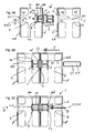
- two frame structure members 2 can be connected to one another to form a system 1, by means of insert 4, sleeve 3 and securing pin 5. This is illustrated in figures 2A-C and 3A-C .
- FIG 2A it is shown that a series of three inserts 4 is introduced (arrow A) into the inner space 10 of the members 2 until they all have their edges 26 aligned with the edges of the apertures 11-14.
- the outer ends of the members 2 are closed off by end plates 30 (arrow P), for instance by means of a press-fit or adhesive.
- the sleeve 3 is first inserted (arrow B) with its half 15a into an aperture 12 in side 7 of member 2a and into accommodation space 22, wherein the stop edges 19a engage behind the edge 27. Thereafter, the assembly of member 2a, inserts 4 and sleeve 3 is moved (arrow C) towards and against the end of member 2b.
- the sleeve half 15b is introduced into aperture 31 of member 2b and into the accommodation space 22 present there, until the side 7 of member 2a abuts the end face of member 2b and the stop edges 19b engage behind stop edge 27 of the ring 23 which connects to aperture 31.
- the flange 17 fits into apertures 12 and 31.
- the securing pin 5 is inserted, arrow D, figure 2C , through an aperture 14 in side 9 of member 2a, which side is opposite the side 7 that abuts the end plate 30 of member 2b, through the accommodation space 22 debouching in aperture 14 and through the inner space 40 in insert 4.
- Securing pin 5 is then pushed (possibly by using an ordinary tool such as a screwdriver or by using one's index finger) into the passage 29 in sleeve 3 until all lips 18a,b are engaged by surface 20 of the pin 5 and are thereby fixed against a radially inward bending movement.
- both members 2a,b are connected to one another in a reliable manner to form part of a piece of furniture, such as a chair, or possibly a playing house or a dog house.
- the length L 3 is larger than the spacing between the edges 27 of two opposite rings 23, the pin 5 will be guided by the rings 23 when passing through inner space 40.
- FIG. 3A-C A similar process of connecting can be seen in detail in figures 3A-C .
- the accommodation space 22 connecting to (first) aperture 11 communicates with (second) aperture 13 by the inner or central space 40 of the insert 4 and a further accommodation space 22 at aperture 13, so that a passage 50 inside the member 2a,b is created for pin 5.
- the lips 18a bend inwardly, arrow E.
- the edges 19a have moved beyond the edge 27 of ring 23, they will move radially outwards, arrow F, figure 3B , after which the edges 19a engage behind the edge 27.
- the sleeve half 15a corresponds to the inner diameter D5 of ring 23, the sleeve fits into the ring 23 without play. Due to the fact that the outer diameter D1 of the flange corresponds to the diameter D6 of the aperture 11. the flange 17 can move into the aperture 11. The inner diameter D5 of the edges 26 is smaller than the diameter D6, so that a step is formed against which the flange 17 abuts. Then, the flange 17 fits for half its thickness in the aperture 11. The sleeve 3 is now secured against axially movement in two opposite directions.
- the other member 2b is moved against member 2a, during which the aperture 11 is moved over the lips 18b of sleeve 3, until the stop edges 19b engage behind edge 27 of insert 4 in member 2b and the flange 11 is received for the other half of its thickness in the aperture 11 of structure member 2b.
- the sides 6 of both structure members 2a,b then abut one another.
- the securing pin 5 is inserted through aperture 13 (arrow D), moved through passage 50 towards and into sleeve 3 and pushed into sleeve 3, for instance using a finger or an ordinary screwdriver, until end plane 21b is at the location of the stop edges 19b, which can be seen by the user.
- the pin 5 Since the length L3 of the cylindrical surface of the pin 5 corresponds to the length L1, the user can be sure that the other, leading end is at the location of the stop edges 19a. Due to the fact that the outer diameter D3 of pin 5 corresponds to inner diameter of the passage 29, the pin fits snugly in the sleeve 3 and a radially inward movement of the lips 18a,b is prevented.
- the axis S,T,U and V are aligned.
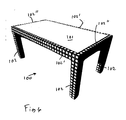
- a table 100 is shown, composed of four structure members 102 and four structure members 102', as well as a plate 101.
- the members 102, 102'and 102" correspond to members 2a,b.
- the connection between members 102 and 102' can be realized as described above.
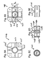
- FIG. 5A,B an alternative embodiment of an insert, 204, is shown, in which the edges 226 have an inner circumference that is not round, in this example polygonal, octagonal.
- FIG. 5C,D a sleeve 203 is shown, in which the sleeve halves 215a,b are provided with two thin flanges 217 and with unround circumferential edges 240a,b, in this example polygonal, octagonal, to match edges 226.
- edges 226 and 240a,b will interengage, as a result of which a relative rotation about axis S,U is prevented and the members 2a,b cannot rotate with respect to one another, also due to the strength against torsion of sleeve 203 and the fixed position of the inserts 204 in members 202a,b.
- a solid structure member can be used, for instance structure member 102 shown in figure 1E .
- the accommodation spaces 122 have been milled, as well as a central space 140 extending in longitudinal direction starting at aperture 130 in end plane 128.
- the inner edges 127 of the inner walls 123 of the spaces 122 form the stop edges for the stop edges 19a,b of the sleeve 3.
- Securing pin 5 can be provided in two parts, in which case their combined length can be L3, their end planes axially abutting one another after both pin halves have been inserted into the sleeve 3. In this case, however, the user has to place two securing parts.
- sleeves corresponding to a half of the sleeve 3 or the like and provided with a connection portion as mentioned above, wherein such a half-sleeve is provided with a part having a particular function, such as a closing plate, preferably flush fitting into the aperture, in a desired colour, so that other, exposed apertures 11-14 can be closed. It is also possible to combine such half-sleeves with other useful parts, such as a hook for clothes, a support for a shelf, a hinge blade, a screw or bolt.
- the half-sleeve may be provided with the above mentioned lips with stop edges for engaging stop edges in the structure member concerned, in particular provided on an insert in the structure member.
- the connection of the half-sleeve to the structure member may be secured by a securing device, such as a pin, adapted for that purpose.
- connection system for structures in particular for pieces of furniture and their components, has been described herein. This and other variations, which will be appreciated by those skilled in the art, are within the intended scope of this disclosure as claimed below. As previously stated, detailed embodiments of the present disclosure are disclosed herein; however, it is to be understood that the disclosed embodiments are merely exemplary of the disclosure that may be embodied in various forms.
Landscapes
- Assembled Shelves (AREA)
Applications Claiming Priority (1)
| Application Number | Priority Date | Filing Date | Title |
|---|---|---|---|
| NL1035101A NL1035101C1 (nl) | 2008-02-28 | 2008-02-28 | Bouwsysteem bestaande uit een vierhoekige buis met regelmatige uitsparingen aan de vier zijden waarmee - in combinatie met de binnenwerk blokjes - elk gewenst bouwwerk of meubelstuk kan worden geconstrueerd. |
Publications (1)
| Publication Number | Publication Date |
|---|---|
| EP2095740A1 true EP2095740A1 (fr) | 2009-09-02 |
Family
ID=39461987
Family Applications (1)
| Application Number | Title | Priority Date | Filing Date |
|---|---|---|---|
| EP09002728A Withdrawn EP2095740A1 (fr) | 2008-02-28 | 2009-02-26 | Système de connexion d'éléments de structure |
Country Status (2)
| Country | Link |
|---|---|
| EP (1) | EP2095740A1 (fr) |
| NL (1) | NL1035101C1 (fr) |
Citations (5)
| Publication number | Priority date | Publication date | Assignee | Title |
|---|---|---|---|---|
| US2665927A (en) * | 1950-06-20 | 1954-01-12 | United Carr Fastener Corp | Joint for colateral superimposed tubular members |
| US3333874A (en) * | 1965-10-23 | 1967-08-01 | Joseph S Gelfarb | Structural wood connector and joint |
| US6322305B1 (en) | 1999-04-01 | 2001-11-27 | Karl Simon Gmbh & Co. Kg | Mounting element used in furniture building |
| DE10118952A1 (de) | 2001-04-18 | 2002-10-24 | Horst Haber | Holz- und Werkstoffniete |
| DE202008002486U1 (de) * | 2008-02-22 | 2008-07-31 | Kenmark Industrial Co. Ltd. | Plattenverbinder |
-
2008
- 2008-02-28 NL NL1035101A patent/NL1035101C1/nl not_active IP Right Cessation
-
2009
- 2009-02-26 EP EP09002728A patent/EP2095740A1/fr not_active Withdrawn
Patent Citations (5)
| Publication number | Priority date | Publication date | Assignee | Title |
|---|---|---|---|---|
| US2665927A (en) * | 1950-06-20 | 1954-01-12 | United Carr Fastener Corp | Joint for colateral superimposed tubular members |
| US3333874A (en) * | 1965-10-23 | 1967-08-01 | Joseph S Gelfarb | Structural wood connector and joint |
| US6322305B1 (en) | 1999-04-01 | 2001-11-27 | Karl Simon Gmbh & Co. Kg | Mounting element used in furniture building |
| DE10118952A1 (de) | 2001-04-18 | 2002-10-24 | Horst Haber | Holz- und Werkstoffniete |
| DE202008002486U1 (de) * | 2008-02-22 | 2008-07-31 | Kenmark Industrial Co. Ltd. | Plattenverbinder |
Also Published As
| Publication number | Publication date |
|---|---|
| NL1035101C1 (nl) | 2008-03-21 |
Similar Documents
| Publication | Publication Date | Title |
|---|---|---|
| CA2309454C (fr) | Systeme de construction modulaire avec couplage rotatif | |
| AU2012321373B2 (en) | A connector system for structural framework | |
| EP3017201B1 (fr) | Raccord de tube | |
| US8157470B2 (en) | Coupling between two objects, object intended therefor, and mocular building system | |
| RU2738755C2 (ru) | Усовершенствованное приспособление для соединения деталей мебели и мебельных аксессуаров | |
| AU2013101784A4 (en) | Device for facilitating assembly of a product, such as furniture | |
| WO2007100871A3 (fr) | Corps creux de structure emboitable et procedes relatifs | |
| US20100014912A1 (en) | Set of Components Able to Be Coupled Together | |
| EP0611002A1 (fr) | Elément d'assemblage démontable rapide en particulier pour meubles | |
| CA2415931A1 (fr) | Dispositif de fixation de panneau | |
| CN104994923A (zh) | 玩偶组件 | |
| EP2588764B1 (fr) | Ensemble de construction pour structure spatiale avec vis mobile | |
| US12133592B2 (en) | Modular assembly with polymagnets | |
| JP2021530106A (ja) | 一体型磁気式および機械式固定装置 | |
| US4076429A (en) | Convertible tube connecting system | |
| US9097324B2 (en) | Construction assembly for spatial structure with drive shaft | |
| EP1885978B1 (fr) | Unité d'étagère repliable | |
| AU2007314156B2 (en) | Modular furniture system | |
| KR101925706B1 (ko) | 조립식 프레임 | |
| JP4691274B2 (ja) | 組立家具用パネル及び組立家具 | |
| JP2011103928A (ja) | 組立てavラック及びこれに用いられる板材固定具 | |
| KR20100005068U (ko) | 중첩되는 연결 구조를 갖는 다단 조립식 수납구의 지지대. | |
| WO2015124902A1 (fr) | Meuble en kit modulaire | |
| US20250084935A1 (en) | Universal Connector | |
| WO2023099798A1 (fr) | Structure modulaire à assemblage par emboîtement sous pression |
Legal Events
| Date | Code | Title | Description |
|---|---|---|---|
| PUAI | Public reference made under article 153(3) epc to a published international application that has entered the european phase |
Free format text: ORIGINAL CODE: 0009012 |
|
| AK | Designated contracting states |
Kind code of ref document: A1 Designated state(s): AT BE BG CH CY CZ DE DK EE ES FI FR GB GR HR HU IE IS IT LI LT LU LV MC MK MT NL NO PL PT RO SE SI SK TR |
|
| AX | Request for extension of the european patent |
Extension state: AL BA RS |
|
| AKX | Designation fees paid | ||
| REG | Reference to a national code |
Ref country code: DE Ref legal event code: 8566 |
|
| STAA | Information on the status of an ep patent application or granted ep patent |
Free format text: STATUS: THE APPLICATION IS DEEMED TO BE WITHDRAWN |
|
| 18D | Application deemed to be withdrawn |
Effective date: 20100623 |