EP2095835B1 - Gerät zum Überwachen eines Gefässzugangs zu einem Patienten - Google Patents
Gerät zum Überwachen eines Gefässzugangs zu einem Patienten Download PDFInfo
- Publication number
- EP2095835B1 EP2095835B1 EP09008205A EP09008205A EP2095835B1 EP 2095835 B1 EP2095835 B1 EP 2095835B1 EP 09008205 A EP09008205 A EP 09008205A EP 09008205 A EP09008205 A EP 09008205A EP 2095835 B1 EP2095835 B1 EP 2095835B1
- Authority
- EP
- European Patent Office
- Prior art keywords
- blood
- flow rate
- values
- pump
- characteristic
- Prior art date
- Legal status (The legal status is an assumption and is not a legal conclusion. Google has not performed a legal analysis and makes no representation as to the accuracy of the status listed.)
- Expired - Lifetime
Links
- 230000002792 vascular Effects 0.000 title claims description 163
- 238000012544 monitoring process Methods 0.000 title claims description 43
- 239000008280 blood Substances 0.000 claims description 215
- 210000004369 blood Anatomy 0.000 claims description 215
- 230000017531 blood circulation Effects 0.000 claims description 107
- 238000000034 method Methods 0.000 claims description 79
- 238000013178 mathematical model Methods 0.000 claims description 66
- 238000011282 treatment Methods 0.000 claims description 58
- 238000004364 calculation method Methods 0.000 claims description 54
- 230000004872 arterial blood pressure Effects 0.000 claims description 29
- 238000005534 hematocrit Methods 0.000 claims description 26
- 239000012530 fluid Substances 0.000 claims description 25
- 238000000108 ultra-filtration Methods 0.000 claims description 24
- 230000008859 change Effects 0.000 claims description 22
- 238000001514 detection method Methods 0.000 claims description 17
- 238000001631 haemodialysis Methods 0.000 claims description 17
- 230000000322 hemodialysis Effects 0.000 claims description 17
- 238000011144 upstream manufacturing Methods 0.000 claims description 15
- 230000006870 function Effects 0.000 claims description 11
- 230000004087 circulation Effects 0.000 claims description 10
- 239000000126 substance Substances 0.000 claims description 9
- 230000009885 systemic effect Effects 0.000 claims description 8
- 230000008569 process Effects 0.000 claims description 4
- 230000036772 blood pressure Effects 0.000 claims description 3
- 238000002615 hemofiltration Methods 0.000 claims description 2
- 239000012528 membrane Substances 0.000 claims description 2
- 238000002616 plasmapheresis Methods 0.000 claims description 2
- 230000001839 systemic circulation Effects 0.000 claims 2
- 230000000704 physical effect Effects 0.000 claims 1
- 206010016717 Fistula Diseases 0.000 description 41
- 230000003890 fistula Effects 0.000 description 41
- 208000031481 Pathologic Constriction Diseases 0.000 description 20
- 238000004422 calculation algorithm Methods 0.000 description 16
- 238000005259 measurement Methods 0.000 description 15
- 230000000004 hemodynamic effect Effects 0.000 description 14
- 230000036262 stenosis Effects 0.000 description 13
- 208000037804 stenosis Diseases 0.000 description 13
- 238000010586 diagram Methods 0.000 description 11
- 239000000243 solution Substances 0.000 description 10
- 238000000502 dialysis Methods 0.000 description 8
- 238000012360 testing method Methods 0.000 description 8
- 230000004075 alteration Effects 0.000 description 5
- 230000000875 corresponding effect Effects 0.000 description 5
- 238000002560 therapeutic procedure Methods 0.000 description 5
- 230000008901 benefit Effects 0.000 description 4
- 230000002596 correlated effect Effects 0.000 description 4
- 238000012417 linear regression Methods 0.000 description 4
- 239000007788 liquid Substances 0.000 description 4
- 208000001647 Renal Insufficiency Diseases 0.000 description 3
- 230000003872 anastomosis Effects 0.000 description 3
- 239000000385 dialysis solution Substances 0.000 description 3
- 238000006073 displacement reaction Methods 0.000 description 3
- 230000000694 effects Effects 0.000 description 3
- 230000002706 hydrostatic effect Effects 0.000 description 3
- 201000006370 kidney failure Diseases 0.000 description 3
- 241000283690 Bos taurus Species 0.000 description 2
- 208000007536 Thrombosis Diseases 0.000 description 2
- 238000004458 analytical method Methods 0.000 description 2
- 210000000748 cardiovascular system Anatomy 0.000 description 2
- 230000002526 effect on cardiovascular system Effects 0.000 description 2
- 238000000338 in vitro Methods 0.000 description 2
- 230000003287 optical effect Effects 0.000 description 2
- 238000005457 optimization Methods 0.000 description 2
- 210000000056 organ Anatomy 0.000 description 2
- 230000003068 static effect Effects 0.000 description 2
- 210000003462 vein Anatomy 0.000 description 2
- 241001631457 Cannula Species 0.000 description 1
- YTAHJIFKAKIKAV-XNMGPUDCSA-N [(1R)-3-morpholin-4-yl-1-phenylpropyl] N-[(3S)-2-oxo-5-phenyl-1,3-dihydro-1,4-benzodiazepin-3-yl]carbamate Chemical compound O=C1[C@H](N=C(C2=C(N1)C=CC=C2)C1=CC=CC=C1)NC(O[C@H](CCN1CCOCC1)C1=CC=CC=C1)=O YTAHJIFKAKIKAV-XNMGPUDCSA-N 0.000 description 1
- 230000036765 blood level Effects 0.000 description 1
- 238000009530 blood pressure measurement Methods 0.000 description 1
- 210000004204 blood vessel Anatomy 0.000 description 1
- 238000009529 body temperature measurement Methods 0.000 description 1
- 230000000747 cardiac effect Effects 0.000 description 1
- 229940000032 cardiovascular system drug Drugs 0.000 description 1
- 239000000470 constituent Substances 0.000 description 1
- 230000001276 controlling effect Effects 0.000 description 1
- 238000012937 correction Methods 0.000 description 1
- 238000010790 dilution Methods 0.000 description 1
- 239000012895 dilution Substances 0.000 description 1
- 238000011156 evaluation Methods 0.000 description 1
- 238000001914 filtration Methods 0.000 description 1
- 238000009472 formulation Methods 0.000 description 1
- 210000003734 kidney Anatomy 0.000 description 1
- 208000017169 kidney disease Diseases 0.000 description 1
- 230000004807 localization Effects 0.000 description 1
- 239000000203 mixture Substances 0.000 description 1
- 238000012806 monitoring device Methods 0.000 description 1
- 239000002674 ointment Substances 0.000 description 1
- 230000001575 pathological effect Effects 0.000 description 1
- 230000000737 periodic effect Effects 0.000 description 1
- 230000002572 peristaltic effect Effects 0.000 description 1
- 230000002685 pulmonary effect Effects 0.000 description 1
- 230000001105 regulatory effect Effects 0.000 description 1
- 230000011664 signaling Effects 0.000 description 1
- 238000004088 simulation Methods 0.000 description 1
- 230000006439 vascular pathology Effects 0.000 description 1
Images


Classifications
-
- A—HUMAN NECESSITIES
- A61—MEDICAL OR VETERINARY SCIENCE; HYGIENE
- A61M—DEVICES FOR INTRODUCING MEDIA INTO, OR ONTO, THE BODY; DEVICES FOR TRANSDUCING BODY MEDIA OR FOR TAKING MEDIA FROM THE BODY; DEVICES FOR PRODUCING OR ENDING SLEEP OR STUPOR
- A61M1/00—Suction or pumping devices for medical purposes; Devices for carrying-off, for treatment of, or for carrying-over, body-liquids; Drainage systems
- A61M1/36—Other treatment of blood in a by-pass of the natural circulatory system, e.g. temperature adaptation, irradiation ; Extra-corporeal blood circuits
- A61M1/3621—Extra-corporeal blood circuits
-
- A—HUMAN NECESSITIES
- A61—MEDICAL OR VETERINARY SCIENCE; HYGIENE
- A61M—DEVICES FOR INTRODUCING MEDIA INTO, OR ONTO, THE BODY; DEVICES FOR TRANSDUCING BODY MEDIA OR FOR TAKING MEDIA FROM THE BODY; DEVICES FOR PRODUCING OR ENDING SLEEP OR STUPOR
- A61M1/00—Suction or pumping devices for medical purposes; Devices for carrying-off, for treatment of, or for carrying-over, body-liquids; Drainage systems
- A61M1/36—Other treatment of blood in a by-pass of the natural circulatory system, e.g. temperature adaptation, irradiation ; Extra-corporeal blood circuits
- A61M1/3621—Extra-corporeal blood circuits
- A61M1/3653—Interfaces between patient blood circulation and extra-corporal blood circuit
-
- A—HUMAN NECESSITIES
- A61—MEDICAL OR VETERINARY SCIENCE; HYGIENE
- A61M—DEVICES FOR INTRODUCING MEDIA INTO, OR ONTO, THE BODY; DEVICES FOR TRANSDUCING BODY MEDIA OR FOR TAKING MEDIA FROM THE BODY; DEVICES FOR PRODUCING OR ENDING SLEEP OR STUPOR
- A61M1/00—Suction or pumping devices for medical purposes; Devices for carrying-off, for treatment of, or for carrying-over, body-liquids; Drainage systems
- A61M1/36—Other treatment of blood in a by-pass of the natural circulatory system, e.g. temperature adaptation, irradiation ; Extra-corporeal blood circuits
- A61M1/3621—Extra-corporeal blood circuits
- A61M1/3653—Interfaces between patient blood circulation and extra-corporal blood circuit
- A61M1/3655—Arterio-venous shunts or fistulae
-
- A—HUMAN NECESSITIES
- A61—MEDICAL OR VETERINARY SCIENCE; HYGIENE
- A61M—DEVICES FOR INTRODUCING MEDIA INTO, OR ONTO, THE BODY; DEVICES FOR TRANSDUCING BODY MEDIA OR FOR TAKING MEDIA FROM THE BODY; DEVICES FOR PRODUCING OR ENDING SLEEP OR STUPOR
- A61M1/00—Suction or pumping devices for medical purposes; Devices for carrying-off, for treatment of, or for carrying-over, body-liquids; Drainage systems
- A61M1/36—Other treatment of blood in a by-pass of the natural circulatory system, e.g. temperature adaptation, irradiation ; Extra-corporeal blood circuits
- A61M1/3621—Extra-corporeal blood circuits
- A61M1/3653—Interfaces between patient blood circulation and extra-corporal blood circuit
- A61M1/3656—Monitoring patency or flow at connection sites; Detecting disconnections
-
- A—HUMAN NECESSITIES
- A61—MEDICAL OR VETERINARY SCIENCE; HYGIENE
- A61M—DEVICES FOR INTRODUCING MEDIA INTO, OR ONTO, THE BODY; DEVICES FOR TRANSDUCING BODY MEDIA OR FOR TAKING MEDIA FROM THE BODY; DEVICES FOR PRODUCING OR ENDING SLEEP OR STUPOR
- A61M1/00—Suction or pumping devices for medical purposes; Devices for carrying-off, for treatment of, or for carrying-over, body-liquids; Drainage systems
- A61M1/36—Other treatment of blood in a by-pass of the natural circulatory system, e.g. temperature adaptation, irradiation ; Extra-corporeal blood circuits
- A61M1/3621—Extra-corporeal blood circuits
- A61M1/3663—Flow rate transducers; Flow integrators
-
- A—HUMAN NECESSITIES
- A61—MEDICAL OR VETERINARY SCIENCE; HYGIENE
- A61M—DEVICES FOR INTRODUCING MEDIA INTO, OR ONTO, THE BODY; DEVICES FOR TRANSDUCING BODY MEDIA OR FOR TAKING MEDIA FROM THE BODY; DEVICES FOR PRODUCING OR ENDING SLEEP OR STUPOR
- A61M1/00—Suction or pumping devices for medical purposes; Devices for carrying-off, for treatment of, or for carrying-over, body-liquids; Drainage systems
- A61M1/36—Other treatment of blood in a by-pass of the natural circulatory system, e.g. temperature adaptation, irradiation ; Extra-corporeal blood circuits
- A61M1/3621—Extra-corporeal blood circuits
- A61M1/3623—Means for actively controlling temperature of blood
-
- A—HUMAN NECESSITIES
- A61—MEDICAL OR VETERINARY SCIENCE; HYGIENE
- A61M—DEVICES FOR INTRODUCING MEDIA INTO, OR ONTO, THE BODY; DEVICES FOR TRANSDUCING BODY MEDIA OR FOR TAKING MEDIA FROM THE BODY; DEVICES FOR PRODUCING OR ENDING SLEEP OR STUPOR
- A61M1/00—Suction or pumping devices for medical purposes; Devices for carrying-off, for treatment of, or for carrying-over, body-liquids; Drainage systems
- A61M1/36—Other treatment of blood in a by-pass of the natural circulatory system, e.g. temperature adaptation, irradiation ; Extra-corporeal blood circuits
- A61M1/3621—Extra-corporeal blood circuits
- A61M1/3639—Blood pressure control, pressure transducers specially adapted therefor
Definitions
- the invention relates to a system for monitoring vascular access in a patient undergoing extracorporeal blood treatment.
- the invention can be usefully applied in the field of extracorporeal treatment for kidney failure.
- the blood taken from the patient and sent through an extramporeal circuit, is subjected to a treatment, generally passing through a treatment unit (for example a dialyzer filter) and thereafter returned to the patient.
- a treatment unit for example a dialyzer filter
- the vascular access is where the blood is removed from the cardio-vascular system of the patient and returned to the system.
- Cimino-Brescia artero-venous fistula access One of the vascular accesses most commonly used in hemodialysis therapy is the Cimino-Brescia artero-venous fistula access. Other vascular access types are known, however. For reasons of simplicity the present description will make reference to the artero-venous fistula as an example of vascular access, without excluding other types of vascular access from the claimed field of protection.
- the blood is usually taken from the vascular access by an arterial needle fluidly connected to the extracorporeal circuit. After having passed through the treatment unit, the blood is sent back to the vascular access through a venous needle.
- a positive displacement pump generally peristaltic.
- One of the problems of extracorporeal blood treatment is monitoring the efficiency of the vascular access.
- a parameter indicative of this efficiency is the blood flow rate which the vascular access can supply. This flow rate is usually greater than the blood flow rate through the extracorporeal circuit. For example, in normal conditions the blood flow rate at the vascular access is about 800 ⁇ 1200 ml/minute, while the blood flow rate in the extracorporeal circuit varies between 100 and 700 ml/minute.
- the flow rate at the vascular access can diminish due to a vascular pathology, such as, for example, a stenosis, i.e. a narrowing of the blood passage section, or for example due to a drop in cardiac output.
- a vascular pathology such as, for example, a stenosis, i.e. a narrowing of the blood passage section, or for example due to a drop in cardiac output.
- the presence and location of a stenosis at the vascular access should be determined as soon as possible in order to prevent the stenosis degenerating into a thrombosis (occlusion of the blood vessels).
- a reduced-efficiency vascular access can lead to the undesirable phenomenon of recirculation of blood during treatment.
- Recirculation consists in the presence during treatment of blood flow proceeding in an opposite to the desired direction, i.e. from the return zone of the treated blood (venous needle) to the supply zone of the blood to be treated (arterial needle).
- Flow recirculation therefore consists in return (in the extracorporeal circuit) of blood which has already been subjected to treatment, with a consequent diminution in treatment efficiency.
- EP 1 044 695 A2 which discloses an apparatus as in the preamble of claim 1, teaches a method for determining the blood flow rate in a vascular access during hemodialysis treatment.
- the method varies the blood flow rate of the extracorporeal circuit and measures the arterial and venous pressures in the extracorporeal circuit during the above-cited flow rate variations.
- the operations are carried out in two different conditions: first with the vascular access open, in which a part of the blood flow passes through the vascular access between the withdrawal needle and the return needle, and then when the vascular access is closed, in which the vascular access flow between withdrawal needle and return needle is zero.
- vascular access blood flow rate is judged to be equal to the blood pump flow rate at which the difference of arterial pressure (or venous pressure) in the two different situations is zero.
- This method has the drawback that it is necessary to intervene mechanically on the fistula to interrupt blood flow.
- WO 00/18451 teaches a method for determining the flow in a fistula of a patient using an extracorporeal blood flow circuit, such as for example a hemodialysis circuit, in which the blood flows from a withdrawal point in the fistula to a return point in the fistula.
- the method varies the blood flow rate in the extracorporeal circuit and takes a reading of a signal which can be correlated with the fistula flow rate downstream of the withdrawal point.
- the blood flow rate upstream of the withdrawal point is evaluated at equal the blood flow rate obtaining in the extracorporeal circuit when the fistula blood flow rate downstream, read with the above-described signal, is zero.
- WO 00/18451 includes an embodiment in which the signal which can be correlated to the fistula blood flow downstream of the withdrawal point is generated by an ultrasonic sensor which operates directly on the patient's vascular access.
- EP 1 020 199 A2 teaches a method for detecting the presence of a stenosis in a vascular access during extracorporeal blood treatment.
- the method includes the use of at least one pressure sensor predisposed in the extracorporeal circuit along the arterial line upstream of the blood pump.
- a stenosis can be calculated from the entity of the pressure pulse measured by the pressure sensor.
- a pressure sensor can be placed on the arterial line too downstream of the blood pump and upstream of a dialyzer, and a further pressure sensor can be placed on the venous line downstream of the dialyzer.
- the method also includes a reading of the pressure pulse frequency and use of that frequency as a signal entity correction factor.
- the pressure pulse frequency signal can be corrected by means of a function depending on the blood pump flow rate.
- the data deductible from the method described in EP 1 020 199 A2 is however limited: in particular, the method provides only a general indication of the hemodynamic state of the fistula, signalling the presence of a stenosis, but it cannot gather more detailed data, such as for example the vascular access blood flow rate or the location of any stenoses found.
- US 5,830,365 teaches a method for determining some hemodynamic parameters, among which the blood flow rate in a fistula during an extracorporeal blood treatment.
- the method involves the alteration of at least one chemical-physical characteristic of the blood in the venous line of the extracorporeal circuit, and recording the change which occurs in the arterial line following this alteration.
- the alteration can be a change in the concentration of an indicator, or a change in the temperature or pressure.
- the concentration of the indicator increases by effect of back-filtration through the dialyzer.
- the concentration of the indicator increases by effect of recirculation in the fistula.
- the change of concentration in the arterial and venous lines is read by ultrasonic sensors. Alteration (in this case the change in concentration) is performed in two stages: first when the blood flows in the normal direction through the extracorporeal circuit, then when the blood flows in the opposite direction.
- the method includes the use of a device for inverting the blood flow direction in the extracorporeal circuit.
- the change in concentration measured in the first stage enables calculation of recirculation at normal flow rate, while the change in concentration measured in the second stage enables calculation of recirculation when the flow is inverted.
- the two calculated values thus enable a calculation of various hemodynamic parameters among which the blood flow rate in the fistula.
- WO 02/04044 teaches a method for identifying problems in arterial flow during an extracorporeal blood treatment in which the blood is transferred, by means of a positive displacement pump, from the vascular access of a patient to a blood treatment device through an arterial line and then sent by the treatment device to the vascular access through a venous line of the extracorporeal circuit.
- the method consists in measuring the amplitude of the periodic variations in pressure in the venous line induced by the rotation of the blood pump, by comparing the variations with a threshold value and generating a control signal if the threshold value is exceeded.
- WO 02/04044 further describes another method according to which, during a dialysis treatment, the amplitude of the periodical variations of the pressure of the dialysis fluid (and not the venous line) is measured. The result is compared with a threshold value and if the threshold value is exceeded a control signal is generated.
- US 6,221,040 discloses a system for monitoring a vascular access during a dialysis treatment in which the pressures in both the arterial and venous branches of the extracorporeal blood system are monitored by pressure sensors.
- a computer unit generates first and second characteristic values for the integrity of the vascular access from measured arterial and venous pressures.
- An analyser unit analyses the integrity of the vascular access by comparing the first and second characteristic values to first and second ranges of predetermined values.
- Calculating a sum of the venous and arterial pressure generates the first characteristic value, and calculating a difference between the venous and the arterial pressure generates the second characteristic value.
- the object of US 6,221,040 is to provide a monitoring system that allows detection of the venous cannula slipping out of the vascular access as well as detection of a blood leak in the venous branch of the extracorporeal circuit. It is not directed to determination of fistula flow.
- US 5,866,015 and EP 0 773 035 disclose a method for determining hemodynamic parameters during an extracorporeal hemotherapy, including the steps of measuring the blood temperature in the arterial branch of the extracorporeal circuit, varying the blood flow in the extracorporeal circuit, storing the values of the extracorporeal blood flow and the measured values of the blood temperature, and determining a value of the blood flow from the stored sequence of value pairs of blood temperature and of extracorporeal blood flow, at which value, after it is exceeded, the amount of the change in the blood temperature within a specific blood flow interval is greater than a predetermined limiting value.
- the fistula flow is inferred from the determined blood flow value.
- the method is based on the fact that the measuring curve existing in discrete measured values is able to be represented by two subfunctions, the first subfunction indicating the blood temperature as a function of the extracorporeal blood flow for blood flow values smaller than the fistula flow or equal to the fistula flow, and the second subfunction indicating the blood temperature as a function of the blood flow for blood flow values greater than or equal to the fistula flow.
- the intersection of the two subfunctions indicates the point where the extracorporeal blood flow equals fistula flow.
- the point is able to be defined where fistula recirculation begins, i.e., where blood flow equals fistula flow.
- the concentration of a blood constituent can also be measured, as can the density, speed of sonic propagation, optical density, and conductivity or viscosity.
- the blood characteristic to be measured must have a different value in the venous branch of the extracorporeal circuit than it does in the blood flowing to fistula. It is assumed that the blood characteristic, preferably the temperature, is kept constant in the venous branch of the extracorporeal circuit while the measured values are recorded. If this characteristic is not constant, a regulating device to keep the characteristic in the venous branch constant must be provided. In the case of a temperature measurement, for example, this can be realized as a temperature controller.
- Another drawback of this method is that the delivery rate of blood pump, which predetermines the extracorporeal blood flow, is increased starting from a lower value to an upper limiting value which must be greater than the fistula flow to be expected. Fistula flows can only be determined within the adjustable blood flow range. Therefore the fistula flow is not determinable if it is equal to or greater than the upper limiting value of the adjustable blood flow range.
- the method is based on the determination of the venous and arterial pressures (upstream of the blood pump) in an extracorporeal blood circuit connected to the vascular access to be monitored.
- the method comprises a preliminary stage in which, through in vitro tests in which the extracorporeal circuit is not connected to a real vascular access, fluid resistances in the arterial and venous lines of the extracorporeal circuit are calculated.
- the extracorporeal circuit is connected to the real vascular access of the patient in order to initiate an extracorporeal treatment.
- the venous and arterial pressures are calculated in the extracorporeal circuit.
- the venous and arterial pressures in the extracorporeal circuit are known, as are the fluid resistances in the arterial and venous lines of the extracorporeal circuit, the pressures in the vascular access can be calculated.
- the dynamic measurement at different flow rates and the comparison with static measures enables stenoses at the vascular access to be identified.
- pressures which correspond to the pressures which would be measured by two pressure sensors directly connected to the withdrawal and return needles, are used in order to identify the presence of a stenosis.
- a knowledge of the pressures both at the point of withdrawal and at the point of return of the vascular access provides more accurate indications and enables a first approximate localization of the stenosis, especially enabling to detect if the stenosis is in venous tract or is located between the needles.
- the method described here is not however able to determine the blood flow rate in the vascular access.
- the model which includes three parameters (resistance to flow of the anastomosis, resistance between arterial and venous access, the resistance which expresses the efficiency of venous circulation drainage), was used to analyse the data gathered during a normal hemodialysis therapy operation.
- the abstract states that the extracorporeal venous and arterial pressures were measured after having set four different flow rates on the blood pump and that the above-cited parameters included in the mathematical model were calculated using the mathematical model.
- the present invention provides a system for controlling vascular access adequacy during an extracorporeal blood treatment.
- An aim of the invention is to enable calculation of some hemodynamic parameters at the vascular access. Knowledge of these parameters enables both regulation of the blood pump flow rate operation in the extracorporeal circuit and intervention in case of detection of a pathological situation in the vascular access.
- a further aim of the invention is to enable evaluation of the blood flow circulating in the vascular access of a patient during an extracorporeal blood treatment.
- a further aim of the invention is to make available a system for evaluating vascular hydraulic resistance in various tracts of the patient's vascular system.
- an aim of the invention is to evaluate vascular resistance upstream of the blood withdrawal zone from the vascular access, downstream of the blood return zone, and in the tract of vascular access comprised between the withdrawal zone and the return zone.
- An advantage of the invention is that it provides indicative values of the efficiency of the vascular access simply, automatically, using devices (such as for example pressure transducers, blood pump, drainage pump) which are normally already present in machines for extracorporeal blood treatment.
- devices such as for example pressure transducers, blood pump, drainage pump
- the invention enables monitoring of the vascular access at any time during the extracorporeal blood treatment.
- a further advantage of the invention is that the monitoring procedure does not cause extra stress to the patient.
- the procedure can be carried out by means of variations in the blood pump or the drainage pump flow rates, or both, within flow rate intervals which are normally compatible with the extracorporeal treatment the patient undergoes.
- the intervals can be those normally used during the course of therapy.
- a mathematical model which contains at least two parameters in which a first parameter relates to the hemodynamics of the vascular access. and a second pammeter retates to the blood flow rate in the ectracorporeal circuit.
- the mathematical model comprises a third parameter relating to at least one blood characteristic: this characteristic can be any physical, chemical or physical-chemical property thereof winch characterises the blood in a vessel and which can be related to the blood flow rate in that vessel.
- a peculiarity of the invention is that the mathematical model used describes the relationship between the selected blood property (physical, chemical or physical-chemical) and the blood flow rate in the vesset.
- the mathematical model describes the relationship in the vascular acccess.
- the mathematical model can describe the fluid-dynamic situation of the vascular access; the model can describe a relationship between the difference of pressure at two points of the vascular access and the flow rate crossing the points.
- the pressure it is also possible to select other properties (physical, chemical or physical-chemical) of the blood which are influenced by the flow rate, such as, for example: the difference in induced potential, speed of sound, optical characteristics, temperature, concentration of an indicator, and so on.
- the monitoring of the vascular access is performed by varying the flow rate of at least one fluid (for example blood or the product of ultrafiltration), which runs either in the extracorporeal circuit or in at least one hydraulic line (for example an ultrafiltration line) connected to the extraorporeal circuit.
- at least one fluid for example blood or the product of ultrafiltration
- at least one hydraulic line for example an ultrafiltration line
- the monitoring can be carried out by varying both the above-cited flows.
- the monitoring determines the values of at least one characteristic of the blood, in at least one zone of the blood circulation path, and at at least two different values of the flow rate of the fluid.
- the cited characteristic of the blood can be a physical, chemical or chemical-physical one.
- the selected charateristic to be used is the pressure.
- the monitoring procedure involves calculating one or more of the hemodynamic parameters of the vascular access contained in the mathematical model, using the values of the blood characteristic determined previously during the course of the procedure.
- a multiplicity of values of the blood characteristic is determined, then the said hemodynamic parameters are calculated, by means of the mathematical model, using approximation algorithms (of known type).
- the algorithms can be chosen, for example, from those which enable determination of the value of the hemodynamic parameter, by virtue of which the blood characcteristic values calculated using the mathematical model, at different flow rate values, are those which are closest to the blood characteristic values which were previously determined during the course of the procedure, at the same flow rate values.
- the mathematical model used is descriptive of the pressure variation at the vascular access: it comprises at least one hemodynamic parameter relative to at least one characteristic of the vascular access; at least one parameter relative to the blood characteristic; and at least one parameter relative to the blood flow rate in the extracorporeal circuit.
- the hemodynamic parameter can be relative to at least one of the following characteristics of the vascular access: the blood flow rate upstream of a withdrawal zone of the blood from the access, the blood flow rate between the withdrawal zone and a blood return zone at the access, the blood flow rate downstream of the blood return zone, the vascular hydraulic resistance upstream of the blood withdrawal zone from the access, the vascular hydraulic resistance between the blood withdrawal zone and the blood return zone, and the vascular hydraulic resistance downstream of the blood return zone.
- the monitoring procedure includes determining the values assumed by the blood characteristic in at least two zones of the blood circulation path (where the blood circulation path comprises both the intracorporeal circuit and the extracorporeal circuit) and at at least two different flow rate values of one fluid (blood or the product of ultrafiltration).
- the monitoring procedure includes determining the values assumed by the blood characteristic in at least one zone of the blood circulation path and at at least two different flow rate values of two fluids (blood and the product of ultrafiltration).
- the monitoring comprises a measuring stage of a blood characteristic, in a zone of the extracorporeal circuit arranged downstream of the blood withdrawal zone, or in a zone arranged upstream of the blood return zone, or in both above zones.
- the monitoring includes determining the blood characteristic in the vascular access, in the withdrawal zone, or in the return zone, or in both zones, by means of one or more mathematical models describing the variation of the said blood characteristic between the zones of withdrawal and return in the vascular access and the measuring zones in the extracorporeal circuit.
- the mathematical models can be, in particular, models descriptive of the variation of the said blood characteristic in the passage through the arterial or venous needles.
- these mathematical models comprise at least one parameter which is relative to the blood flow, or at least one parameter relative to the hematocrit of the blood, or both said parameters.
- the mathematical models can be represented by one or more interpolating formulas of experimental data; the formulas can be, for example, second-order polynomials with one or more parameters chosen between the flow rate and the hematocrit of the blood.
- the monitoring procedure determines the values assumed by the blood characteristic in at least one zone of the blood circulation path during the flow rate change, evaluates the variation of the blood characteristic, selects the values assumed by the blood characteristic when the variation has exceeded a threshold limit value, and uses the selected values to calculate the value of the blood characteristic at the vascular access.
- the monitoring procedure determines the values of the blood characteristic in two different zones of the blood circulation path during flow rate change, compares the variation of the blood characteristic detected in a first zone of the blood circulation path and the variation of the characteristic detected in a second zone thereof, selects the values of the blood characteristic when the difference between the variations has exceeded a threshold limit value, and uses the selected values in calculating the value of the blood characteristic at the vascular access.
- the monitoring procedure in calculating the value of the characteristic of the vascular access, the monitoring procedure considers the values of the blood characteristic in a stationary blood flow situation, i.e. after having kept the flow rate constant for a determined period of time.
- the monitoring procedure is applied by means of a machine for blood treatment in an extracorporeal circuit, in particular for a machine for treatment of kidney failure, predisposed to perform one or more of the following therapies: hemodialysis, hemofiltration, hemodiafiltration, pure ultrafiltration, plasmapheresis.
- the machine is provided with a timer for carrying out the monitoring procedure at least once during the extracorporeal treatment.
- the monitoring procedure can be initiated on command of an operator, or automatically at a predetermined moment during the treatment.
- the extracorporeal circuit can be included in the complex of fluid distribution lines, of the disposable type, normally removably associated and used in a machine for treatment of renal failure.
- the machine is normally equipped with pressure transducers operating in the blood withdrawal line, before the blood pump, and in the blood return line, after the blood treatment unit
- the machine illustrated in figure 1 is a machine for hemodiafiltration comprising a unit for an extracorporeal blood treatment (a filter for hemodiafiltration 1) having two chambers 2, 3 separated by a semipermeable membrane 4.
- a first chamber 2 has an inlet which is connected to an arterial line 5 (blood withdrawal line from the patient) of an extracorporeal blood circuit.
- the arterial line 5 is connectable with a vascular access 6 of a patient by means of an access tool constituted in the example by an arterial needle N A .
- the arterial line 5 is provided with a pressure sensor 8 and a positive displacement pump 9 for blood circulation along the extracorporeal circuit in the direction of the arrow 7.
- the first chamber 2 has an outlet connected to a venous line 10 (blood return line to the patient) of the extracorporeal blood circuit.
- the venous line 10 is connectable to the vascular access 6 of the patient by means of an access tool constituted in the illustrated embodiment by a venous needle Nv.
- the venous line 10 is provided with a pressure sensor 12.
- the second chamber 3 of the filter 1 has an inlet connected to a supply line 14 of a fresh treatment fluid (dialysis liquid) and an outlet connected to a discharge line 15 of a discharge fluid (the dialysis liquid and the ultrafiltered liquid).
- the supply line 14 is provided with a supply pump 13 of the fresh treatment fluid.
- the discharge line 15 is provided with a drainage pump 16 for the circulation of the discharge fluid in the direction of the arrow 11.
- the dialysis machine further comprises a control and calculation unit 17 connected to a screen and also to a keyboard through which the user communicates to the control and calculation unit the setting values for machine operation.
- One of the setting values which the control and calculation unit 17 receives from the user is the blood flow rate q b in the arterial blood withdrawal line 5.
- the control and calculation unit 17 can control the speed of the blood pump 9 in order to have the predetermined value of flow rate q b .
- the control and calculation unit 17 can be connected to at least one measuring device, able to provide information relating to the effective blood flow rate in the arterial line.
- the measuring device can comprise, for example, a flowmeter, or an encoder connected to the rotor of a blood-pump.
- the control and calculation unit 17 is further connected to the pressure sensors 8 and 12 and receives therefrom the signals indicating the detected pressure.
- the control and calculation unit 17 controls the operation of the various motor devices of the machine, in particular the blood pump 9 and drainage pump 16, according to the instructions received from the user and the programmed algorithms contained in its memory.
- the machine can further comprise sensors (of known type and not illustrated) for detecting the blood viscosity upstream and downstream of the treatment unit 1.
- the sensors can comprise, for example, measuring devices for the blood hematocrit level.
- the control and calculation unit is programmed to carry out, automatically or by request of the user, a series of operations which enable the vascular access to be monitored.
- FIG 2 shows the patient's blood circulation subjected to extracorporeal treatment with the machine of figure 1 .
- the vascular access 6, through which the extracorporeal blood circuit is connected to the cardio-vascular circuit of the patient is, in the embodiment, a fistula of the Cimino-Brescia type.
- H indicates the patient's heart
- P denotes the pulmonary circuit
- V denotes the vascular system (or systemic circuit, or intravascular circuit or intracorporeal circuit).
- the arterial line 5 and the venous line 10 are connected at one end to the vascular access 6 and at the other end to the dialysis filter 1.
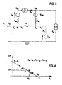
- Figure 3 shows an electrical diagram which, by analogy, describes the blood circulation of the patient subjected to the extracorporeal blood treatment.
- the nodes where the extracorporeal circuit meets with the vascular access are the zones where pressures P af e P vf are determined (either directly measured or calculated).
- the mathematical model describes the variation of pressure in the vascular access as a function of the blood flow rate.
- the pressures in the above-indicated mathematical model relate to atmospheric pressure.
- the arterial and venous pressures P af and P vf in the vascular access are measurable directly, for example using pressure sensors operating directly on the vascular access 6 in proximity or internally of the arterial and venous needles N A e Nv.
- the pressures P af and P vf are also determinable indirectly using a mathematical model which includes, among its parameters, pressures P am and P vm (arterial and venous pressures) measured in the extracorporeal circuit by the pressure sensors 8 and 12.
- the prior art comprises various mathematical models usable for calculating pressures P af and P vf when pressures P am and P vm are known. Some of the above-cited prior art contains examples of so-usable mathematical models. There follows a further example of a mathematical model usable for determining the intravascular pressures of the blood starting from the easily-measurable values of the extracorporeal blood pressures.
- Resistances R am and R vm can be considered equal, with satisfactory approximation, to the hydraulic resistance of the arterial needle N A and, respectively, the venous needle Nv; it is therefore assumed for the sake of simplicity that the whole drop in pressure in the arterial and venous lines is concentrated at the respective needles.
- a 2 , A 1 , B 2 , B 1 and B 0 are coefficients characteristic of each needle, the value being obtained by means of experimental preliminary laboratory testing, by measuring the fall of pressure through the needle with different blood and hematocrit flow rates.
- the flow rate was varied within a range from 0 to 500 ml/minute, while the hematocrit was varied within a range from 30 to 45%.
- the coefficients differ for a same needle according to blood flow direction, that is whether the needle is used as an arterial needle or as a venous needle.
- the tests include simulation of the extracorporeal treatment (for example dialysis) using a machine for performing the treatment (for example a dialysis machine) with an extracorporeal circuit lacking the device for effecting the treatment (for example lacking a dialyzer filter), causing bovine blood to circulate, exiting from a container and returning thereto.
- the blood is kept at a constant temperature of 37°C.
- the blood hematocrit is measured.
- the machine and the circuit used in the tests can be the same as those illustrated in figure 1 .
- the same operations are repeated, each time controlledly changing the value of the hematocrit in the bovine blood.
- R A 2 ⁇ q b 2 + A 1 ⁇ q b + b 1 and we thus obtain, for each type of needle, a pair of coefficients A 2 and A 1 for each flow direction (i.e. we obtain a pair of coefficients which characterise the arterial needle and a pair of coefficients which characterise the venous needle).
- Coefficient b 1 depends on the blood hematocrit value.
- the control and calculation unit 17 memory is preloaded with the coefficient values A 2 , A 1 , B 2 , B 1 and B 0 of the most commonly used needles (the memory contains two series of coefficients for each needle, one for each blood flow direction, i.e. a series relating to a needle's use as an arterial needle and as a venous needle).
- the control and calculation unit 17 recognises the needle used in the extracorporeal treatment time by time and consequently in the calculation of P af and P vf uses the coefficients relating to the needle being used.
- Recognition of the needle can be automatic (for example by means of an identification system associated to the needle) or can be user-guided.
- the unknown quantities q a and R f can be determined by calculating the optimal solution of the above-indicated equation system.
- the processor calculates the two values, one q a and the other R f , for which the corresponding values of ⁇ P f calculated by the above-indicated system of equations are the closest to the ⁇ P fi values previously determined at point e.
- Graph ⁇ P f - q b of figure 2 illustrates this mode of procedure.
- the points in figure 2 represent the determined values ⁇ P fi of ⁇ P f according to the blood pump flow rate q b .
- the straight line interpolating the various points is the graphic representation of the linear mathematical relation which connects ⁇ P f with q b .
- the interpolation method can be any known linear interpolation method.
- the straight line of interpolation intersects the horizontal axis (q b ) at q, and the vertical axis ( ⁇ P f ) at R f q a .
- Another way of calculating q, and R f is based on the description of the relation between q b and ⁇ P f using a non-linear mathematical relation (for example a polynomial of a degree greater than one), derived by the processor with an interpolation method using the values stored in the memory q bi , P afi e P vfi .
- a non-linear mathematical relation for example a polynomial of a degree greater than one
- q bi are selected so that the difference between the minimum value and the maximum value of q bi does not exceed a predefined value (for example about 600 ml/min) in order that q a and R f can be considered as constant in the calculation with good approximation.
- a predefined value for example about 600 ml/min
- the resistance R d stored in the memory can be one of the R di calculated with equation (1) or the mean value of the calculated R di .
- R di P a - P afi q a
- the blood flow rate in the extracorporeal circuit q b is kept constant at a known value which is not zero.
- the unknown quantities q a and R v can be determined by calculating the optimal solution of the above-indicated equation system.
- N 2 the two unknowns q, and R v can be determined using an optimization algorithm.
- the value of R v can be calculated by a simple division.
- the plot of ⁇ P vf as a function of q uf in figure 5 illustrates this mode of procedure.
- the straight line interpolating the various points is the graphic representation of the linear mathematical relation which connects ⁇ P f with q uf .
- the interpolation method can be any known linear interpolation method.
- the straight interpolating line intersects the horizontal axis q uf at q a and the vertical axis of ⁇ P vf at R v ⁇ q a .
- R fi P afi - P vfi q a - q b ⁇ 1
- the R f value stored at point k. can be one of the calculated values for R fi or the mean value of the R fi values.
- R di P a - P afi q a
- the R d value stored at point 1. can be one of the calculated values R di or the mean value of the R di values.
- the third operating mode calculates at least a part of the coefficients C a0 , C a1 , C a2 and C v0 , C v1 , C v1 and from these derives R d , R f and R v .
- the calculation of the coefficients is done starting from one or more known values for each of the following quantities: P a , q b, q uf , P v , P af and P vf .
- the quantities P a , q b , q uf , P v are known through measurement.
- the quantities P af and P vf are known by direct measurement of the pressures in the vascular access, or by a process of calculation starting from the measurement of the pressures in the machine P am and P vm .
- q uf at qb constant (for example ⁇ 0) is varied and P am measured at different values of q uf .
- the third operating mode is now described step by step.
- the processor determines the four coefficients c a0 , c a1 , c v0 . and c v1 and from these it calculates the three resistances R d , R v , R f .
- the pressures P af and P vf in the vascular access are determined, either by direct measuring or by measuring pressures P am e P vm in the extracorporeal circuit and calculating P af and P vf by means of a mathematical model.
- the pressures P af and P vf are determined at different values of the blood flow rate q b .
- the arterial and venous pressures P a and P v of the patient are also considered in the calculation of the coefficients.
- coefficients c a0 , c a1 , c v0 , and c v1 are greater in number than resistances R d , R f and R v , there exists a multiplicity of relations between the coefficients and resistances.
- the knowledge of three coefficients enables determination of the resistances. It has been found that the most precise determination of the resistances R d , R f and R v is obtained by using the three coefficients, c a0 , c a1 , and c v0 .
- determination of the value of P v can be performed in two ways.
- the fifth operating mode is similar to the third, with the difference that, instead of determining P af , P vf is determined.
- the fifth operating mode consists in varying the blood flow rate q b while maintaining the ultrafiltration rate q uf constant, in varying the ultrafiltration rate while keeping the blood flow rate q b constant, and in determining the venous pressure in the vascular access P vf at various values of the above-mentioned flow rates.
- the flow rate of the vascular access q a is calculated as in the third operative mode.
- the measurements are taken with the system in a steady state.
- the various measurements are taken after a certain time interval (for example about ten seconds) after the blood flow rate or the ultrafiltration rate has been changed.
- This example uses the above-described first monitoring procedure, applied to the apparatus of figure 1 .
- the second example uses the fourth monitoring procedure.
Landscapes
- Health & Medical Sciences (AREA)
- Heart & Thoracic Surgery (AREA)
- Vascular Medicine (AREA)
- Life Sciences & Earth Sciences (AREA)
- Engineering & Computer Science (AREA)
- Anesthesiology (AREA)
- Biomedical Technology (AREA)
- Hematology (AREA)
- Cardiology (AREA)
- Animal Behavior & Ethology (AREA)
- General Health & Medical Sciences (AREA)
- Public Health (AREA)
- Veterinary Medicine (AREA)
- Physics & Mathematics (AREA)
- Fluid Mechanics (AREA)
- External Artificial Organs (AREA)
Claims (26)
- Gerät zur Überwachung eines Gefäßzugangs, der einem extrakorporalen Blutkreislauf zugeordnet ist, umfassend:- mindestens eine erste Pumpe (9, 16) zur Zirkulation eines Fluids in mindestens einem des extrakorporalen Blutkreislaufs bzw. mindestens einer Fluidförderleitung (15), die mit dem Kreislauf zusammenarbeitet;- einen Speicher; und- eine Steuer- und Recheneinheit (17), die mit dem Speicher und der ersten Pumpe (9, 16) verbunden ist;dadurch gekennzeichnet dass:der Speicher ein erstes mathematisches Modell des Gefäßzugangs (6) enthält, umfassend:ο mindestens einen ersten Parameter betreffend mindestens eine Kenngröße (Rd, Rf, Rv, qa, qf, qv) des Gefäßzugangs;ο mindestens einen zweiten Parameter betreffend mindestens eine Kenngröße (P) des Blutes; undο mindestens einen dritten Parameter betreffend einen Durchfluss (qb, quf) des durch die erste Pumpe (9; 16) bewegten Fluids;wobei die Steuer- und Recheneinheit (17) programmiert ist zur Ausführung eines Überwachungsverfahrens, dass die folgenden Betriebsschritte umfasst:ο Ändern des Durchflusses der ersten Pumpe (9; 16);ο Empfangen der Signale, die den Werten (Paf, Pam, Pvf, Pvm) der Kenngröße (P) des Blutes in mindestens einem Bereich des Blutkreislaufs entsprechen, und mit mindestens zwei verschiedenen Werten des Durchflusses (qb, quf) der ersten Pumpe (9; 16);ο Speichern der Werte der Blutkenngröße und der entsprechenden Durchflusswerte der ersten Pumpe (9; 16);ο Verarbeiten der gespeicherten Werte durch das erste mathematische Modell, um mindestens einen Wert der Kenngröße des Gefäßzugangs zu bestimmen;wobei die Steuer- und Recheneinheit (17) konfiguriert ist zum Empfangen der Signale, die den Werten der Blutkenngröße in mindestens einem ersten Erfassungsbereich und/oder einem zweiten Erfassungsbereich des extrakorporal Blutkreislaufs entsprechen, wobei der erste Erfassungsbereich von einem Blutentnahmebereich des Gefäßzugangs (6) entfernt liegt und der zweite Erfassungsbereich von einem Blutrückgabebereich des Gefäßzugangs (6) entfernt liegt;wobei der Speicher:ο ein zweites mathematisches Modell der Blutkenngrößenänderung zwischen dem Blutentnahmebereich und dem ersten Erfassungsbereich, und/oderο ein drittes mathematisches Modell der Blutkenngrößenänderung zwischen dem Blutrückgabebereich und dem ersten Erfassungsbereich, enthält;wobei die Steuer- und Recheneinheit (17) programmiert ist zur Verarbeitung:ο unter Verwendung des zweiten mathematischen Modells, der Werte der Blutkenngröße des ersten Erfassungsbereichs, und zur Bestimmung mindestens eines Wertes der Blutkenngröße, der den Blutentnahmebereich betrifft; und/oderο unter Verwendung des dritten mathematischen Modells, der Werte der Blutkenngröße des zweiten Erfassungsbereichs, und zur Bestimmung mindestens eines Wertes der Blutkenngröße, der den Blutrückgabebereich betrifft.
- Gerät nach Anspruch 1, wobei der zweite Parameter eine physische Eigenschaft oder eine chemische Eigenschaft oder eine chemisch-physische Eigenschaft des Blutes betrifft, die eine Beziehung mit dem Blutdurchfluss aufweist, wobei das erste mathematische Modell die Beziehung beschreibt.
- Gerät nach einem der vorhergehenden Ansprüche, wobei der erste Parameter mindestens eine strömungsdynamische Kenngröße des Gefäßzugangs betrifft, wobei das erste mathematische Modell ein strömungsdynamisches Modell des Gefäßzugangs ist.
- Gerät nach einem der vorhergehenden Ansprüche, wobei der mindestens eine Wert der Kenngröße des Gefäßzugangs durch Berechnung von mindestens einer Lösung des ersten mathematischen Modells bestimmt wird, wobei insbesondere die optimale Lösung des ersten mathematischen Modells berechnet wird.
- Gerät nach einem der vorhergehenden Ansprüche, wobei- der extrakorporale Kreislauf mit einer ersten Kammer (2) der Blutbehandlungseinheit (1) verbunden ist, die eine zweite Kammer (3), die durch eine semipermeable Membran (4) von der ersten Kammer (2) getrennt ist, aufweist, wobei die zweite Kammer (3) einen Ausgang, der mit einer Abflussleitung (15) für ein Abflussfluid verbunden ist, aufweist;- die erste Pumpe eine Drainagepumpe (16) ist zur Zirkulation des Abflussfluids in der Abflussleitung (15), wobei das Fluid das Abflussfluid ist und die mit dem extrakorporalen Kreislauf zusammenarbeitende Fluidförderleitung die Abflussleitung (15) ist.
- Gerät nach einem der vorhergehenden Ansprüche, wobei die Steuer- und Recheneinheit (17) programmiert ist zum:- Empfangen von Signalen, die den Werten der Blutkenngröße in mindestens zwei verschiedenen Bereichen des Blutkreislaufs entsprechen, und für mindestens zwei verschiedenen Werte des Durchflusses der ersten Pumpe (9; 16);- Speichern der Werte der Blutkenngröße und der entsprechenden Durchflusswerte der ersten Pumpe (9; 16) im Speicher;- Verarbeiten der im Speicher gespeicherten Werte unter Verwendung des ersten mathematischen Modells, um mindestens einen Wert der Gefäßzugangskenngröße zu bestimmen.
- Gerät nach einem der vorhergehenden Ansprüche, umfassend mindestens eine zweite Pumpe (9, 16) zur Zirkulation eines Fluids im anderen entweder des extrakorporalen Blutkreislaufs bzw. der mit dem extrakorporalen Blutkreislauf zusammenarbeitenden Fluidförderleitung (15), wobei das erste mathematische Modell des Gefäßzugangs (6) mindestens einen vierten Parameter betreffend den Durchfluss (qb, quf) des in der zweiten Pumpe zirkulierten Fluids umfasst, wobei bevorzugt die Steuer- und Recheneinheit (17) mit der zweiten Pumpe (9; 16) verbunden ist und das Überwachungsverfahren weiter die folgenden Schritte umfasst:- Ändern des Durchflusses der zweiten Pumpe (9, 16);- Empfangen der Signale, die den Werten der Blutkenngröße in mindestens einem Bereich des Blutkreislaufs entsprechen, und für mindestens zwei verschiedenen Werte des Durchflusses der zweiten Pumpe (9; 16);- Speichern der Werte der Blutkenngröße und der entsprechenden Durchflusswerte der zweiten Pumpe (9; 16) im Speicher;- Verarbeiten der gespeicherten Werte durch das erste mathematische Modell, um mindestens einen Wert der Kenngröße des Gefäßzugangs zu bestimmen, wobei noch bevorzugter die Steuer- und Recheneinheit (17) programmiert ist zum:- Empfangen von Signalen, die den Werten der Blutkenngröße in mindestens zwei verschiedenen Bereichen des Blutkreislaufs entsprechen, und für mindestens zwei verschiedenen Werte des Durchflusses der zweiten Pumpe (9; 16);- Speichern der Werte der Blutkenngröße und der entsprechenden Durchflusswerte der zweiten Pumpe (9; 16) im Speicher;- Verarbeiten der gespeicherten Werte unter Verwendung des ersten mathematischen Modells, um mindestens einen Wert der Gefäßzugangskenngröße zu bestimmen.
- Gerät nach dem vorhergehenden Anspruch, wobei die Steuer- und Recheneinheit (17) programmiert ist zum Empfangen von mindestens zwei Signalen, für mindestens zwei verschiedenen Werte des Durchflusses der ersten Pumpe und denselben Wert des Durchflusses der zweiten Pumpe, wobei die Steuer- und Recheneinheit bevorzugt programmiert ist zum Empfangen von mindestens zwei Signalen, für mindestens zwei verschiedenen Werte des Durchflusses der zweiten Pumpe und denselben Wert des Durchflusses der ersten Pumpe, wobei insbesondere die Steuer- und Recheneinheit programmiert ist, um den Durchfluss der zweiten Pumpe während der Änderung des Durchflusses der ersten Pumpe konstant aufrechtzuerhalten, wobei weiter insbesondere die Steuer- und Recheneinheit programmiert ist, um den Durchfluss der ersten Pumpe während der Änderung des Durchflusses der zweiten Pumpe konstant aufrechtzuerhalten.
- Gerät nach einem der vorhergehenden Ansprüche, wobei:- das erste mathematische Modell mindestens einen Parameter betreffend mindestens eine Kenngröße (Pa, Pv) des systemischen Kreislaufs eines Patienten umfasst, wobei insbesondere die Kenngröße des systemischen Kreislaufs des Patienten der systemische arterielle Druck (Pa) ist;- die Steuer- und Recheneinheit (17) konfiguriert ist zum Empfangen von mindestens einem Signal entsprechend der Kenngröße (Pa, Pv).
- Gerät nach einem der vorhergehenden Ansprüche, wobei der das Fluid Blut ist und die erste Pumpe eine Blutpumpe (9) ist, die konfiguriert ist zur Blutzirkulation im extrakorporalen Kreislauf, wobei der extrakorporale Blutkreislauf (5, 10) mit dem Gefäßzugang in einem Blutentnahmebereich und in einem Blutrückgabebereich verbunden ist.
- Gerät nach Anspruch 10, wobei die Steuer- und Recheneinheit (17) mit mindestens einem ersten Sensor (8), insbesondere einem Drucksensor, zur Erfassung von mindestens einem Wert der Blutkenngröße in einem Bereich zwischen dem Blutentnahmebereich und einer Blutpumpe (9) verbunden ist, wobei der Werterfassungsbereich auch den Blutentnahmebereich umfasst, wobei die Steuer- und Recheneinheit (17) auch ein Signal entsprechend dem erfassten Wert aussendet.
- Gerät nach Anspruch 10 oder 11, wobei der erste Sensor (8) konfiguriert ist zum Betrieb im extrakorporalen Kreislauf (5, 10), aufwärts von der Blutpumpe (9), oder wobei der erste Sensor konfiguriert ist zum Betrieb im Blutentnahmebereich des Gefäßzugangs.
- Gerät nach einem der Ansprüche 11 bis 12, wobei die Steuer- und Recheneinheit (17) mit mindestens einem zweiten Sensor (12), insbesondere einem Drucksensor, zur Erfassung von mindestens einem Wert der Blutkenngröße in einem Bereich zwischen der Blutpumpe (9) und dem Blutrückgabebereich verbunden ist, wobei der Blutrückgabebereich im Erfassungsbereich eingeschlossen ist; wobei der zweite Sensor ein Signal entsprechend dem erfassten Wert aussendet, wobei insbesondere der zweite Sensor (12) konfiguriert ist zum Betrieb im extrakorporalen Kreislauf abwärts von einer Blutbehandlungseinheit (1) oder der zweite Sensor konfiguriert ist zum Betrieb im Blutrückgabebereich des Gefäßzugangs.
- Gerät nach einem der vorhergehenden Ansprüche, wobei der zweite Parameter betreffend mindestens eine Blutkenngröße ein Parameter betreffend Blutdruck ist, insbesondere in einem Blutentnahmebereich des Gefäßzugangs (6) oder in einem Blutrückgabebereich des Gefäßzugangs (6).
- Gerät nach einem der vorhergehenden Ansprüche, wobei das erste, im Speicher enthaltene mathematische Modell eine Druckänderung im Gefäßzugang (6) abhängig vom Blutdurchfluss beschreibt.
- Gerät nach einem der vorhergehenden Ansprüche, wobei der erste Parameter aus einer Gruppe ausgewählt ist, umfassend die Parameter betreffend eine oder mehrere der folgenden Kenngrößen des Gefäßzugangs (6): der Blutdurchfluss (qa) aufwärts von einem Blutentnahmebereich des Gefäßzugangs (6); der Blutdurchfluss (qf) zwischen dem Blutentnahmebereich und einem Blutrückgabereich zum Gefäßzugang (6); der Blutdurchfluss (qv) abwärts vom Blutrückgabebereich; der hydraulische Gefäßwiderstand (Rd) aufwärts vom Blutentnahmebereich; der hydraulische Gefäßwiderstand (Rf) zwischen dem Blutentnahmebereich und dem Blutrückgabereich; der hydraulische Gefäßwiderstand (Rv) abwärts vom Blutrückgabebereich.
- Gerät nach einem der vorhergehenden Ansprüche, wobei das erste mathematische Modell eine oder mehrere der folgenden Gleichungen umfasst:



- Gerät nach einem der vorhergehenden Ansprüche, wobei mindestens eines der zweiten und dritten mathematischen Modelle mindestens einen Parameter betreffend den Blutdurchfluss umfasst, insbesondere einen Parameter betreffend den Bluthämatokrit.
- Gerät nach einem der vorhergehenden Ansprüche, wobei:- mindestens eines der zweiten und dritten mathematischen Modelle mindestens eine Reihe von experimentell bestimmten Koeffizienten umfasst, die charakteristisch für ein Zugangswerkzeug (NA, NV) sind, das zur Verbindung des extrakorporalen Blutkreislaufs mit dem Gefäßzugang (6) während eines Blutentnahme- oder Blutrückgabeschrittes verwendet wird;- der Speicher Koeffizienten enthält, die charakteristisch für eine Vielzahl von Zugangswerkzeugen (NA, NV) verschiedenen Typs sind, und konfiguriert ist zur Erkennung eines Typs von jeweils verwendetem Zugangswerkzeug und zur Verwendung der Koeffizienten, die charakteristisch für den Typ von erkanntem Zugangswerkzeug sind, in mindestens einem der zweiten und dritten mathematischen Modelle.
- Gerät nach einem der vorhergehenden Ansprüche, umfassend mindestens eine Vorrichtung bekannten Typs, die mit der Steuer- und Recheneinheit (17) verbunden ist und die konfiguriert ist zum Aussenden eines Signals, das den Durchfluss des Fluids angibt, das durch die erste Pumpe in Zirkulation geschickt wird.
- Gerät nach einem der vorhergehenden Ansprüche, wobei die Steuer- und Recheneinheit (17) programmiert ist zum:- Empfangen der Signale betreffend die Werte der Blutkenngrößen, insbesondere des Blutdrucks in regelmäßigen Abständen, in mindestens einem Bereich des Blutkreislaufs während der Änderung des Durchflusses der ersten Pumpe (9; 16);- Bewerten der Änderungen der Werte;- Verwenden der Blutkenngrößenwerte für eine nachfolgende Verarbeitungsoperation, wenn die Änderung einen Schwellenwert überstiegen hat, insbesondere ca. 267 Pa (2 mmHg).
- Gerät nach einem der vorhergehenden Ansprüche, wobei die Steuer- und Recheneinheit (17) programmiert ist zum:- Empfangen der Signale betreffend die Werte der Blutkenngrößen in regelmäßigen Abständen in mindestens zwei verschiedenen Bereichen des Blutkreislaufs während der Änderung des Durchflusses der ersten Pumpe (9; 16);- Berechnen des Unterschieds zwischen der in einem ersten Bereich des Blutkreislaufs erfassten Änderung der Blutkenngröße und der in einem zweiten Bereich des Blutkreislaufs erfassten Änderung der Blutkenngröße;- Verwenden der Blutkenngrößenwerte für die nachfolgende Verarbeitung, wenn die Änderung einen Schwellenwert überstiegen hat.
- Gerät nach einem der vorhergehenden Ansprüche, wobei die Steuer- und Recheneinheit (17) programmiert ist zum:- Erreichen eines stabilen Zustands, nachdem der Durchfluss jeder Pumpe für eine vorgegebene Zeit konstant aufrechterhalten wurde;- Speichern und Verarbeiten von Werten der Blutkenngröße im stabilen Zustand.
- Gerät nach einem der vorhergehenden Ansprüche 7 bis 23, wobei die Steuer-und Recheneinheit (17) programmiert ist zur Ausführung einer Überwachungsprozedur, die die folgenden Betriebsschritte umfasst:- Ändern des Durchflusses der ersten Pumpe;- Ändern des Durchflusses der zweiten Pumpe;- Empfangen von Signalen betreffend die Werte der Blutkenngröße in mindestens einem Bereich des Blutkreislaufs, für mindestens zwei verschiedene Werte des Durchflusses der ersten Pumpe und für mindestens zwei verschiedene Werte des Durchflusses der zweiten Pumpe;- Speichern der Werte der Blutkenngröße und der entsprechenden Werte des Durchflusses der ersten und der zweiten Pumpe;- Verarbeiten der gespeicherten Werte durch das erste mathematische Modell, um mindestens einen Wert der Gefäßzugangskenngröße zu bestimmen.
- Maschine zur Blutbehandlung in einem extrakorporalen Kreislauf, umfassend ein Überwachungsgerät gemäß einem der Ansprüche 1 bis 24, die insbesondere konfiguriert ist zur Ausführung von einer oder mehreren der folgenden Behandlungen:- Hämodialyse;- Hämofiltration;- Hämodiafiltration;- reine Ultrafiltration;- Plasmapherese.
- Maschine nach dem vorhergehenden Anspruch, umfassend einen Zeitgeber, der mit der Steuer- und Recheneinheit (17) verbunden ist, wobei die Steuer- und Recheneinheit (17) die Überwachungsprozedur mindestens einmal während der extrakorporalen Behandlung durchführen kann, wobei insbesondere die Steuer- und Recheneinheit (17) konfiguriert ist zum selektiven Betrieb in mindestens zwei Betriebsarten:- einer ersten Betriebsart, bei der die Überwachungsprozedur durch den Befehl eines Bedieners gestartet wird;- einer zweiten Betriebsart, bei der die Überwachungsprozedur automatisch an einem vorgegebenen Zeitpunkt während der Behandlung gestartet wird.
Applications Claiming Priority (3)
| Application Number | Priority Date | Filing Date | Title |
|---|---|---|---|
| IT000018A ITMO20030018A1 (it) | 2003-01-28 | 2003-01-28 | Apparecchiatura e metodo per il monitoraggio dell'accesso |
| US46605203P | 2003-04-29 | 2003-04-29 | |
| EP04701067A EP1590018B1 (de) | 2003-01-28 | 2004-01-09 | Vorrichtung zur überwachung eines vaskulärenzugangs zu einem patienten |
Related Parent Applications (3)
| Application Number | Title | Priority Date | Filing Date |
|---|---|---|---|
| EP04701067A Division EP1590018B1 (de) | 2003-01-28 | 2004-01-09 | Vorrichtung zur überwachung eines vaskulärenzugangs zu einem patienten |
| EP04701067A Division-Into EP1590018B1 (de) | 2003-01-28 | 2004-01-09 | Vorrichtung zur überwachung eines vaskulärenzugangs zu einem patienten |
| EP04701067.3 Division | 2004-01-09 |
Publications (2)
| Publication Number | Publication Date |
|---|---|
| EP2095835A1 EP2095835A1 (de) | 2009-09-02 |
| EP2095835B1 true EP2095835B1 (de) | 2013-04-03 |
Family
ID=32827137
Family Applications (3)
| Application Number | Title | Priority Date | Filing Date |
|---|---|---|---|
| EP04701067A Expired - Lifetime EP1590018B1 (de) | 2003-01-28 | 2004-01-09 | Vorrichtung zur überwachung eines vaskulärenzugangs zu einem patienten |
| EP08000548A Withdrawn EP1930035A1 (de) | 2003-01-28 | 2004-01-09 | Vorrichtung zur Überwachung des vaskulären Zugangs |
| EP09008205A Expired - Lifetime EP2095835B1 (de) | 2003-01-28 | 2004-01-09 | Gerät zum Überwachen eines Gefässzugangs zu einem Patienten |
Family Applications Before (2)
| Application Number | Title | Priority Date | Filing Date |
|---|---|---|---|
| EP04701067A Expired - Lifetime EP1590018B1 (de) | 2003-01-28 | 2004-01-09 | Vorrichtung zur überwachung eines vaskulärenzugangs zu einem patienten |
| EP08000548A Withdrawn EP1930035A1 (de) | 2003-01-28 | 2004-01-09 | Vorrichtung zur Überwachung des vaskulären Zugangs |
Country Status (5)
| Country | Link |
|---|---|
| US (2) | US7172570B2 (de) |
| EP (3) | EP1590018B1 (de) |
| AU (1) | AU2004208554B2 (de) |
| CA (1) | CA2514239C (de) |
| WO (1) | WO2004067064A1 (de) |
Families Citing this family (69)
| Publication number | Priority date | Publication date | Assignee | Title |
|---|---|---|---|---|
| US8348850B2 (en) * | 2001-07-30 | 2013-01-08 | Henry Ford Health System | Method of monitoring dislodgement of venous needles in dialysis patients |
| US8974394B2 (en) | 2001-07-30 | 2015-03-10 | Henry Ford Health System | Device and method for detecting irregular placement of an extracorporeal vascular access needle |
| CA2488957C (en) * | 2001-07-30 | 2011-09-20 | Henry Ford Health System | Access pressure ratio device and testing method |
| US20040254513A1 (en) | 2002-04-10 | 2004-12-16 | Sherwin Shang | Conductive polymer materials and applications thereof including monitoring and providing effective therapy |
| US10155082B2 (en) | 2002-04-10 | 2018-12-18 | Baxter International Inc. | Enhanced signal detection for access disconnection systems |
| US7052480B2 (en) | 2002-04-10 | 2006-05-30 | Baxter International Inc. | Access disconnection systems and methods |
| US7022098B2 (en) | 2002-04-10 | 2006-04-04 | Baxter International Inc. | Access disconnection systems and methods |
| US8303482B2 (en) * | 2004-09-07 | 2012-11-06 | Micromed | Method and system for physiologic control of a blood pump |
| US7261696B2 (en) * | 2004-09-09 | 2007-08-28 | Transonic Systems, Inc. | Method and apparatus for measuring cardiac output via an extracorporeal cardiopulmonary support circuit |
| DE602005023356D1 (de) | 2005-05-18 | 2010-10-14 | Gambro Lundia Ab | Vorrichtung zur steuerung des blutflusses in einem extrakorporalen kreislauf |
| US7815809B2 (en) * | 2005-12-13 | 2010-10-19 | Gambro Lundia Ab | Method for conductivity calculation in a treatment fluid upstream and downstream a filtration unit in apparatuses for the blood treatment |
| DE102006032815A1 (de) * | 2006-07-14 | 2008-01-17 | Fresenius Medical Care Deutschland Gmbh | Verfahren und Vorrichtung zur Überwachung eines extrakorporalen Blutkreislaufs |
| WO2008057478A2 (en) * | 2006-11-03 | 2008-05-15 | The Regents Of The University Of Michigan | Method and system for determining volume flow in a blood conduit |
| US10463778B2 (en) | 2007-02-09 | 2019-11-05 | Baxter International Inc. | Blood treatment machine having electrical heartbeat analysis |
| US8376978B2 (en) * | 2007-02-09 | 2013-02-19 | Baxter International Inc. | Optical access disconnection systems and methods |
| US8152751B2 (en) | 2007-02-09 | 2012-04-10 | Baxter International Inc. | Acoustic access disconnection systems and methods |
| US8287480B2 (en) * | 2007-06-29 | 2012-10-16 | Jms Co., Ltd. | Hemodialysis apparatus |
| WO2009029677A1 (en) * | 2007-08-27 | 2009-03-05 | Quest Medical, Inc. | Self-adaptive piston blood pump |
| US8197431B2 (en) * | 2007-09-21 | 2012-06-12 | Baxter International Inc. | Acoustic access disconnect detection system |
| US7938792B2 (en) * | 2007-10-01 | 2011-05-10 | Baxter International Inc. | Adaptive algorithm for access disconnect detection |
| DE102008015832B4 (de) * | 2008-03-27 | 2013-08-22 | Fresenius Medical Care Deutschland Gmbh | Verfahren und Vorrichtung zur Überwachung eines Gefäßzugangs sowie extrakorporale Blutbehandlungsvorrichtung mit einer Vorrichtung zur Überwachung eines Gefäßzugangs |
| CA2717886C (en) | 2008-04-01 | 2015-02-10 | Gambro Lundia Ab | An apparatus and a method for monitoring a vascular access |
| US8702637B2 (en) * | 2008-04-14 | 2014-04-22 | Haemonetics Corporation | System and method for optimized apheresis draw and return |
| CN104189968B (zh) | 2008-06-26 | 2017-04-12 | 甘布罗伦迪亚股份公司 | 用于处理时间相关的测量信号的方法及装置 |
| US10089443B2 (en) | 2012-05-15 | 2018-10-02 | Baxter International Inc. | Home medical device systems and methods for therapy prescription and tracking, servicing and inventory |
| US8114043B2 (en) * | 2008-07-25 | 2012-02-14 | Baxter International Inc. | Electromagnetic induction access disconnect sensor |
| US8192388B2 (en) * | 2008-07-25 | 2012-06-05 | Baxter International Inc. | System and method for detecting access disconnection |
| DE102008057994A1 (de) | 2008-11-19 | 2010-05-27 | Fresenius Medical Care Deutschland Gmbh | Verfahren und Vorrichtung zur Erkennung einer paravasalen Blutung |
| US20100152544A1 (en) * | 2008-11-19 | 2010-06-17 | Spectrum Medical Limited | Cardiac monitoring system and method |
| ES2620580T3 (es) | 2009-06-26 | 2017-06-29 | Gambro Lundia Ab | Dispositivo y método para la extracción de datos |
| US8753515B2 (en) | 2009-12-05 | 2014-06-17 | Home Dialysis Plus, Ltd. | Dialysis system with ultrafiltration control |
| US20130006130A1 (en) * | 2009-12-28 | 2013-01-03 | Gambro Lundia Ab | Device and method for monitoring a fluid flow rate in a cardiovascular system |
| KR101720823B1 (ko) | 2009-12-28 | 2017-03-28 | 감브로 룬디아 아베 | 급속 증후성 혈압 감소의 예측을 위한 장치 및 방법 |
| EP2519276B1 (de) | 2009-12-28 | 2015-03-18 | Gambro Lundia AB | Steuerung eines geräts für den flüssigkeitstransfer zu und/oder von einer person |
| DE102010007914A1 (de) * | 2010-02-12 | 2012-12-27 | Fresenius Medical Care Deutschland Gmbh | Vorrichtung und Verfahren zur Überwachung eines Gefäßzugangs für eine extrakorporale Blutbehandlung |
| ES2442875T3 (es) * | 2010-04-28 | 2014-02-14 | Gambro Lundia Ab | Método y dispositivo para monitorizar un estado de un conducto de sangre en una máquina para tratamiento de sangre extracorpóreo |
| US9002655B2 (en) * | 2010-05-03 | 2015-04-07 | Gambro Lundia Ab | Medical apparatus for extracorporeal blood treatment and method for determining a blood parameter value in a medical apparatus thereof |
| US8501009B2 (en) | 2010-06-07 | 2013-08-06 | State Of Oregon Acting By And Through The State Board Of Higher Education On Behalf Of Oregon State University | Fluid purification system |
| EP2463795A1 (de) * | 2010-12-09 | 2012-06-13 | Fresenius Medical Care Deutschland GmbH | Verfahren und Vorrichtungen zum Berechnen oder Approximieren eines oder mehrerer Werte, die Parameter eines Patienten darstellen |
| US11386993B2 (en) | 2011-05-18 | 2022-07-12 | Fenwal, Inc. | Plasma collection with remote programming |
| ES2640953T3 (es) | 2011-10-07 | 2017-11-07 | Outset Medical, Inc. | Purificación de líquido de intercambio de calor para un sistema de diálisis |
| AU2013201556B2 (en) | 2012-07-13 | 2014-06-05 | Gambro Lundia Ab | Filtering of pressure signals for suppression of periodic pulses |
| JP6030803B2 (ja) | 2013-03-11 | 2016-11-24 | アンタレス・ファーマ・インコーポレーテッド | ピニオンシステムを有する用量注射器 |
| WO2014147028A1 (en) | 2013-03-20 | 2014-09-25 | Gambro Lundia Ab | Monitoring of cardiac arrest in a patient connected to an extracorporeal blood processing apparatus |
| DE102013103220A1 (de) * | 2013-03-28 | 2014-10-02 | B. Braun Avitum Ag | Verfahren und Vorrichtung zur Bestimmung eines Rezirkulationszustands |
| DE102013103222A1 (de) * | 2013-03-28 | 2014-10-02 | B. Braun Avitum Ag | Rezirkulationsdetektion durch Bolusgabe |
| JP6324759B2 (ja) * | 2014-03-04 | 2018-05-16 | テルモ株式会社 | 体外循環装置及びその制御方法 |
| EP3838308A1 (de) | 2014-04-29 | 2021-06-23 | Outset Medical, Inc. | Dialysesysteme und -verfahren |
| US20160166211A1 (en) * | 2014-12-02 | 2016-06-16 | Heartware, Inc. | Mean arterial pressure estimation |
| US10220132B2 (en) | 2014-12-19 | 2019-03-05 | Fenwal, Inc. | Biological fluid flow control apparatus and method |
| US10413654B2 (en) | 2015-12-22 | 2019-09-17 | Baxter International Inc. | Access disconnection system and method using signal metrics |
| JP7025408B2 (ja) | 2016-08-19 | 2022-02-24 | アウトセット・メディカル・インコーポレイテッド | 腹膜透析システム及び方法 |
| US11826545B2 (en) | 2016-09-08 | 2023-11-28 | Fresenius Medical Care Holdings, Inc. | Optical blood detection system |
| EP3515531B1 (de) | 2016-09-19 | 2021-11-03 | Henry Ford Health System | System zur überwachung der loslösung von nadeln bei dialysepatienten |
| US10792416B2 (en) | 2017-05-30 | 2020-10-06 | Haemonetics Corporation | System and method for collecting plasma |
| US10758652B2 (en) | 2017-05-30 | 2020-09-01 | Haemonetics Corporation | System and method for collecting plasma |
| US12033750B2 (en) | 2018-05-21 | 2024-07-09 | Fenwal, Inc. | Plasma collection |
| CA3099428C (en) | 2018-05-21 | 2023-09-19 | Fenwal, Inc. | Systems and methods for optimization of plasma collection volumes |
| US11412967B2 (en) | 2018-05-21 | 2022-08-16 | Fenwal, Inc. | Systems and methods for plasma collection |
| BR112021003168A2 (pt) | 2018-08-23 | 2021-05-11 | Outset Medical, Inc. | métodos para preparar um conjunto de tubos e um dialisador, para testar vazamentos, para preparar um conjunto de tubos, para melhorar a durabilidade e operação de uma ou mais bombas de deslocamento e para prover terapia de diálise, sistema de diálise, e, acessório de queima de bomba |
| US20210346651A1 (en) * | 2018-12-31 | 2021-11-11 | Nuwellis, Inc. | Blood flow assisting portable arm support |
| EP3962549B1 (de) | 2019-04-30 | 2025-11-05 | Outset Medical, Inc. | Dialysesystem |
| JP7468276B2 (ja) * | 2020-09-29 | 2024-04-16 | ニプロ株式会社 | 血液流量測定方法、透析装置、および、プログラム |
| EP3991764B1 (de) | 2020-10-27 | 2024-03-06 | Bellco S.r.l. | Durchflussmesser zum dosieren von wasser in einem dialysesystem |
| EP3991770B1 (de) | 2020-10-30 | 2024-10-30 | Bellco S.r.l. | Dialysekassette mit pumpfunktionen |
| US12318528B2 (en) | 2020-10-30 | 2025-06-03 | Mozarc Medical Us Llc | Variable orifice fistula graft |
| EP4008376A1 (de) | 2020-12-03 | 2022-06-08 | Medtronic, Inc. | Flexibles rohr-routing-zubehör für peritoneal dialysis system |
| CN113975505B (zh) * | 2021-11-08 | 2023-12-19 | 中山大学中山眼科中心 | 用于眼球灌注的体外循环系统 |
| DE102023105664A1 (de) * | 2023-03-07 | 2024-09-12 | B.Braun Avitum Ag | Verfahren und System zum automatischen Charakterisieren eines Gefäßzugangs eines Dialysepatienten |
Family Cites Families (182)
| Publication number | Priority date | Publication date | Assignee | Title |
|---|---|---|---|---|
| US523341A (en) * | 1894-07-24 | Bicycle-seat | ||
| US2709785A (en) | 1951-05-03 | 1955-05-31 | Robertshaw Fulton Controls Co | Measurement of conductivity of liquids |
| US3433935A (en) | 1963-07-12 | 1969-03-18 | Herbert Sherman | Apparatus for computation particularly adapted for producing a measure of transit time and the like |
| US3324720A (en) | 1963-07-29 | 1967-06-13 | Friends Of Psychiatric Res Inc | Apparatus and method for determining rate of flow by measurement of electrical property of stream |
| US3404336A (en) | 1965-07-26 | 1968-10-01 | Beckman Instruments Inc | Apparatus for measuring electrical conductivity of a fluid |
| FR1452215A (fr) | 1965-07-28 | 1966-09-09 | Philips Massiot Mat Medic | Dispositif pour mesurer le débit d'un fluide |
| US3396331A (en) | 1965-08-19 | 1968-08-06 | Beckman Instruments Inc | Method of and apparatus for measuring the electrical conductivity of a solution |
| US3450984A (en) | 1965-10-21 | 1969-06-17 | Avco Corp | Method and apparatus for measuring the flow velocity of an electrolytic fluid by electrolysis |
| US3482575A (en) | 1967-02-16 | 1969-12-09 | Single Cell Research Foundatio | Method for the extracorporeal oxygenation of blood |
| US3561266A (en) | 1967-07-10 | 1971-02-09 | Philips Corp | Device for measuring the flow velocity of a fluid |
| US3491592A (en) | 1967-10-23 | 1970-01-27 | Nalco Chemical Co | Measurement of flow rate of aqueous streams |
| GB1203531A (en) | 1968-01-31 | 1970-08-26 | Philips Electronic Associated | Improvements in or relating to a device for measuring the flow intensity of circulating liquid |
| US3545428A (en) | 1968-10-10 | 1970-12-08 | Wilton W Webster Jr | Massflowmeter catheter |
| US3640271A (en) | 1969-06-30 | 1972-02-08 | Ibm | Blood flow pressure measurement technique employing injected bubbled and ultrasonic frequency scanning |
| US3619423A (en) | 1970-04-20 | 1971-11-09 | Us Health Education & Welfare | Cascade dialysis apparatus and method |
| DE2123134C3 (de) | 1970-05-25 | 1979-03-01 | N.V. Philips' Gloeilampenfabrieken, Eindhoven (Niederlande) | Verfahren zum Messen der Strömungsstarke |
| US3946731A (en) * | 1971-01-20 | 1976-03-30 | Lichtenstein Eric Stefan | Apparatus for extracorporeal treatment of blood |
| US4153418A (en) | 1971-05-10 | 1979-05-08 | Haas Rudy M | Chemical tracer method of and structure for determination of instantaneous and total mass and volume fluid flow |
| US3878565A (en) * | 1971-07-14 | 1975-04-22 | Providence Hospital | Vascular prosthesis with external pile surface |
| US3722276A (en) | 1971-12-06 | 1973-03-27 | Tetradyne Corp | Volumetric flow rate measurement of a flowing stream |
| US3868956A (en) * | 1972-06-05 | 1975-03-04 | Ralph J Alfidi | Vessel implantable appliance and method of implanting it |
| US4167870A (en) | 1973-09-07 | 1979-09-18 | Haas Rudy M | Chemical tracer method of and structure for determination of instantaneous and total mass and volume fluid flow |
| NL158390B (nl) | 1973-11-26 | 1978-11-15 | Rhone Poulenc Sa | Inrichting voor buitenlichamelijke bloedkringloop voor dialyse. |
| US3867688A (en) | 1973-12-18 | 1975-02-18 | Atomic Energy Commission | Electrodeless conductance measurement device |
| US3890977A (en) * | 1974-03-01 | 1975-06-24 | Bruce C Wilson | Kinetic memory electrodes, catheters and cannulae |
| FR2266891B1 (de) | 1974-04-05 | 1978-11-17 | Citroen Sa | |
| DE2433092C2 (de) | 1974-07-10 | 1986-10-23 | Robert Bosch Gmbh, 7000 Stuttgart | Antiblockierregelsystem für Vierradfahrzeuge |
| US3964479A (en) | 1974-11-20 | 1976-06-22 | Cobe Laboratories, Inc. | Extracorporeal blood circulation system and drip chamber with adjustable blood level |
| SU521891A1 (ru) | 1975-02-27 | 1976-07-25 | Московский Областной Ордена Трудового Красного Знамени Научно-Исследовательский Клинический Институт Им. М.Ф.Владимирского | Способ ведени гемодиализа |
| US3987788A (en) | 1975-07-09 | 1976-10-26 | American Hospital Supply Corporation | System for computing cardiac flow rates from thermodilution measurements |
| JPS5911864B2 (ja) | 1975-07-14 | 1984-03-19 | 武田薬品工業株式会社 | 漏血検知装置 |
| US4081372A (en) | 1975-12-08 | 1978-03-28 | University Of Utah | Leakage indicator for recirculating peritoneal dialysis system |
| GB1600000A (en) * | 1977-01-24 | 1981-10-14 | Raychem Ltd | Memory metal member |
| US4138639A (en) | 1977-07-14 | 1979-02-06 | Hutchins Thomas B | Fluid conductivity measurement |
| US4136563A (en) | 1977-09-30 | 1979-01-30 | Tetradyne Corporation | Digital volumetric flow rate measurement of a flowing fluid |
| EP0018817A1 (de) | 1979-04-30 | 1980-11-12 | Peter Gilbert Lale | Verfahren und Vorrichtung zur Messung einer Tropfgeschwindigkeit |
| JPS56104646A (en) | 1980-01-25 | 1981-08-20 | Minolta Camera Kk | Optical analyzer for forming ratio of element contained in organism |
| US4361049A (en) | 1980-08-18 | 1982-11-30 | The Hospital For Sick Children | Apparatus for calculating cardiac output |
| SE444640B (sv) * | 1980-08-28 | 1986-04-28 | Bergentz Sven Erik | I djur eller menniska implanterbar kerlprotes samt sett for dess framstellning |
| US4604762A (en) * | 1981-02-13 | 1986-08-12 | Thoratec Laboratories Corporation | Arterial graft prosthesis |
| GB2093192A (en) | 1981-02-16 | 1982-08-25 | Ici Plc | Apparatus for measuring conductivity |
| US4391124A (en) | 1981-02-26 | 1983-07-05 | Cornell Research Foundation, Inc. | Electroacoustic transducer calibration method and apparatus |
| US4434648A (en) | 1981-02-26 | 1984-03-06 | Cornell Research Foundation, Inc. | Electroacoustic transducer calibration method and apparatus |
| SU1013853A1 (ru) | 1981-05-27 | 1983-04-23 | Оренбургский Государственный Медицинский Институт | Способ определени воспалительного процесса в организме |
| US4425908A (en) * | 1981-10-22 | 1984-01-17 | Beth Israel Hospital | Blood clot filter |
| EP0089003B1 (de) | 1982-03-10 | 1987-11-25 | Kabushiki Kaisha Toyota Chuo Kenkyusho | Gerät zur Blutreinigung |
| SE445884B (sv) * | 1982-04-30 | 1986-07-28 | Medinvent Sa | Anordning for implantation av en rorformig protes |
| DE3377897D1 (en) | 1982-06-21 | 1988-10-13 | Fresenius Ag | Dialysis device with controlled composition of dialysis solution |
| DE3223051C2 (de) | 1982-06-21 | 1984-09-13 | Fresenius AG, 6380 Bad Homburg | Dialysevorrichtung mit geregelter Dialysierlösung |
| US4432231A (en) | 1982-06-28 | 1984-02-21 | Baxter Travenol Laboratories, Inc. | Ultrasonic level detector |
| US4512338A (en) * | 1983-01-25 | 1985-04-23 | Balko Alexander B | Process for restoring patency to body vessels |
| US4503569A (en) * | 1983-03-03 | 1985-03-12 | Dotter Charles T | Transluminally placed expandable graft prosthesis |
| US4856321A (en) | 1983-07-29 | 1989-08-15 | Panametrics, Inc. | Apparatus and methods for measuring fluid flow parameters |
| US4665906A (en) * | 1983-10-14 | 1987-05-19 | Raychem Corporation | Medical devices incorporating sim alloy elements |
| US5275622A (en) * | 1983-12-09 | 1994-01-04 | Harrison Medical Technologies, Inc. | Endovascular grafting apparatus, system and method and devices for use therewith |
| US5104399A (en) * | 1986-12-10 | 1992-04-14 | Endovascular Technologies, Inc. | Artificial graft and implantation method |
| US4562596A (en) * | 1984-04-25 | 1986-01-07 | Elliot Kornberg | Aortic graft, device and method for performing an intraluminal abdominal aortic aneurysm repair |
| JPS60190873U (ja) | 1984-05-25 | 1985-12-18 | 松下電工株式会社 | 肛門乾燥用の温風吹出し口の構造 |
| SE458340B (sv) | 1984-06-18 | 1989-03-20 | Gambro Lundia Ab | Blodfiltreringssystem samt dropp- och /eller expansionskammare avsedd foer detta system |
| US4747822A (en) | 1984-07-09 | 1988-05-31 | Peabody Alan M | Continuous flow peritoneal dialysis system and method |
| US4580568A (en) * | 1984-10-01 | 1986-04-08 | Cook, Incorporated | Percutaneous endovascular stent and method for insertion thereof |
| US4728328A (en) * | 1984-10-19 | 1988-03-01 | Research Corporation | Cuffed tubular organic prostheses |
| US4577631A (en) * | 1984-11-16 | 1986-03-25 | Kreamer Jeffry W | Aneurysm repair apparatus and method |
| ES8705239A1 (es) * | 1984-12-05 | 1987-05-01 | Medinvent Sa | Un dispositivo para implantar,mediante insercion en un lugarde dificil acceso, una protesis sustancialmente tubular y radialmente expandible |
| US4739492A (en) | 1985-02-21 | 1988-04-19 | Cochran Michael J | Dialysis machine which verifies operating parameters |
| JPS61196963A (ja) | 1985-02-26 | 1986-09-01 | 株式会社クラレ | 脱血補助装置 |
| US4923464A (en) * | 1985-09-03 | 1990-05-08 | Becton, Dickinson And Company | Percutaneously deliverable intravascular reconstruction prosthesis |
| US4733665C2 (en) * | 1985-11-07 | 2002-01-29 | Expandable Grafts Partnership | Expandable intraluminal graft and method and apparatus for implanting an expandable intraluminal graft |
| US5102417A (en) * | 1985-11-07 | 1992-04-07 | Expandable Grafts Partnership | Expandable intraluminal graft, and method and apparatus for implanting an expandable intraluminal graft |
| DE3640745A1 (de) * | 1985-11-30 | 1987-06-04 | Ernst Peter Prof Dr M Strecker | Katheter zum herstellen oder erweitern von verbindungen zu oder zwischen koerperhohlraeumen |
| US4665918A (en) * | 1986-01-06 | 1987-05-19 | Garza Gilbert A | Prosthesis system and method |
| US4649922A (en) * | 1986-01-23 | 1987-03-17 | Wiktor Donimik M | Catheter arrangement having a variable diameter tip and spring prosthesis |
| SE459641B (sv) | 1986-03-24 | 1989-07-24 | Gambro Ab | Detektorsystem foer kontroll av en foer ledning av blod alternerande med en vaesentligen faergloes vaetska avsedd vaetskeslang |
| US4777938A (en) | 1986-05-02 | 1988-10-18 | Vladimir Sirota | Babysitter toy for watching and instructing child |
| US4740755A (en) | 1986-05-30 | 1988-04-26 | Cobe Laboratories, Inc. | Remote conductivity sensor having transformer coupling in fluid flow path |
| US4825168A (en) | 1986-05-30 | 1989-04-25 | Cobe Laboratories, Inc. | Remote conductivity sensor using square wave excitation |
| DE3620873A1 (de) | 1986-06-21 | 1987-12-23 | Rau Guenter | Vorrichtung zur bestimmung des partialdruckes von in einem fluid geloesten gasen und gasgemischen |
| DE3640089A1 (de) | 1986-11-24 | 1988-06-01 | Fresenius Ag | Verfahren und vorrichtung zur bestimmung des intravasalen blutvolumens waehrend der haemodialyse |
| US4885087A (en) | 1986-11-26 | 1989-12-05 | Kopf Henry B | Apparatus for mass transfer involving biological/pharmaceutical media |
| US4800882A (en) * | 1987-03-13 | 1989-01-31 | Cook Incorporated | Endovascular stent and delivery system |
| DE3720665A1 (de) | 1987-06-23 | 1989-01-05 | Schael Wilfried | Vorrichtung zur haemodialyse und haemofiltration |
| EP0380668B1 (de) * | 1987-10-08 | 1996-12-27 | Terumo Kabushiki Kaisha | Instrument und vorrichtung zum aufrechterhalten des inneren lumendurchmessers eines schlauchförmigen organs |
| US4820298A (en) * | 1987-11-20 | 1989-04-11 | Leveen Eric G | Internal vascular prosthesis |
| US4822341A (en) | 1987-11-20 | 1989-04-18 | Impra, Inc. | Vascular access fistula |
| US5192307A (en) * | 1987-12-08 | 1993-03-09 | Wall W Henry | Angioplasty stent |
| SE465404B (sv) | 1988-03-03 | 1991-09-09 | Gambro Ab | Dialyssystem |
| US4885001A (en) | 1988-06-03 | 1989-12-05 | Cobe Laboratories, Inc. | Pump with plural flow lines |
| US4830003A (en) * | 1988-06-17 | 1989-05-16 | Wolff Rodney G | Compressive stent and delivery system |
| US5230341A (en) | 1988-08-13 | 1993-07-27 | Fresenius Ag | Measuring the change of intravascular blood volume during blood filtration |
| US5019090A (en) * | 1988-09-01 | 1991-05-28 | Corvita Corporation | Radially expandable endoprosthesis and the like |
| CA1322628C (en) * | 1988-10-04 | 1993-10-05 | Richard A. Schatz | Expandable intraluminal graft |
| US5019085A (en) * | 1988-10-25 | 1991-05-28 | Cordis Corporation | Apparatus and method for placement of a stent within a subject vessel |
| US4913141A (en) * | 1988-10-25 | 1990-04-03 | Cordis Corporation | Apparatus and method for placement of a stent within a subject vessel |
| US5078726A (en) * | 1989-02-01 | 1992-01-07 | Kreamer Jeffry W | Graft stent and method of repairing blood vessels |
| DE3909967A1 (de) | 1989-03-25 | 1990-09-27 | Fresenius Ag | Haemodialysegeraet mit automatischer einstellung des dialysierfluessigkeitsflusses |
| US4994071A (en) * | 1989-05-22 | 1991-02-19 | Cordis Corporation | Bifurcating stent apparatus and method |
| US5116318A (en) * | 1989-06-06 | 1992-05-26 | Cordis Corporation | Dilatation balloon within an elastic sleeve |
| US5015253A (en) * | 1989-06-15 | 1991-05-14 | Cordis Corporation | Non-woven endoprosthesis |
| US5207695A (en) * | 1989-06-19 | 1993-05-04 | Trout Iii Hugh H | Aortic graft, implantation device, and method for repairing aortic aneurysm |
| DE3923836C1 (de) | 1989-07-19 | 1990-09-20 | Fresenius Ag, 6380 Bad Homburg, De | |
| US5292331A (en) * | 1989-08-24 | 1994-03-08 | Applied Vascular Engineering, Inc. | Endovascular support device |
| US4995268A (en) | 1989-09-01 | 1991-02-26 | Ash Medical System, Incorporated | Method and apparatus for determining a rate of flow of blood for an extracorporeal blood therapy instrument |
| IE73670B1 (en) * | 1989-10-02 | 1997-07-02 | Medtronic Inc | Articulated stent |
| DE3938662A1 (de) | 1989-11-21 | 1991-07-18 | Fresenius Ag | Verfahren zur in-vivo-bestimmung von parametern der haemodialyse |
| US5108416A (en) * | 1990-02-13 | 1992-04-28 | C. R. Bard, Inc. | Stent introducer system |
| US5078736A (en) * | 1990-05-04 | 1992-01-07 | Interventional Thermodynamics, Inc. | Method and apparatus for maintaining patency in the body passages |
| US5085635A (en) * | 1990-05-18 | 1992-02-04 | Cragg Andrew H | Valved-tip angiographic catheter |
| DE4024434A1 (de) | 1990-08-01 | 1992-02-13 | Fresenius Ag | Vorrichtung zur ultrafiltrationskontrolle bzw. ultrafiltrationsregelung bei blutreinigungsverfahren |
| US5178630A (en) * | 1990-08-28 | 1993-01-12 | Meadox Medicals, Inc. | Ravel-resistant, self-supporting woven graft |
| US5372136A (en) | 1990-10-06 | 1994-12-13 | Noninvasive Medical Technology Corporation | System and method for noninvasive hematocrit monitoring |
| DE9117152U1 (de) * | 1990-10-09 | 1996-07-11 | Cook Inc., Bloomington, Ind. | Stent |
| CS277367B6 (en) * | 1990-12-29 | 1993-01-13 | Krajicek Milan | Three-layered vascular prosthesis |
| CA2202800A1 (en) * | 1991-04-11 | 1992-10-12 | Alec A. Piplani | Endovascular graft having bifurcation and apparatus and method for deploying the same |
| US5304200A (en) * | 1991-05-29 | 1994-04-19 | Cordis Corporation | Welded radially expandable endoprosthesis and the like |
| US5314472A (en) * | 1991-10-01 | 1994-05-24 | Cook Incorporated | Vascular stent |
| US5183085A (en) * | 1991-09-27 | 1993-02-02 | Hans Timmermans | Method and apparatus for compressing a stent prior to insertion |
| US5290305A (en) * | 1991-10-11 | 1994-03-01 | Kanji Inoue | Appliance collapsible for insertion into human organs and capable of resilient restoration |
| US5282860A (en) * | 1991-10-16 | 1994-02-01 | Olympus Optical Co., Ltd. | Stent tube for medical use |
| US5387235A (en) * | 1991-10-25 | 1995-02-07 | Cook Incorporated | Expandable transluminal graft prosthesis for repair of aneurysm |
| US5211658A (en) * | 1991-11-05 | 1993-05-18 | New England Deaconess Hospital Corporation | Method and device for performing endovascular repair of aneurysms |
| FR2683449A1 (fr) * | 1991-11-08 | 1993-05-14 | Cardon Alain | Endoprothese pour implantation transluminale. |
| JPH0771510B2 (ja) | 1991-12-11 | 1995-08-02 | 工業技術院長 | モノクローナル抗体の作成方法 |
| US5192297A (en) * | 1991-12-31 | 1993-03-09 | Medtronic, Inc. | Apparatus and method for placement and implantation of a stent |
| US5316023A (en) * | 1992-01-08 | 1994-05-31 | Expandable Grafts Partnership | Method for bilateral intra-aortic bypass |
| US5507767A (en) * | 1992-01-15 | 1996-04-16 | Cook Incorporated | Spiral stent |
| US5405377A (en) * | 1992-02-21 | 1995-04-11 | Endotech Ltd. | Intraluminal stent |
| US5282823A (en) * | 1992-03-19 | 1994-02-01 | Medtronic, Inc. | Intravascular radially expandable stent |
| US5312550B1 (en) | 1992-04-27 | 1996-04-23 | Robert L Hester | Method for detecting undesired dialysis recirculation |
| US5383928A (en) * | 1992-06-10 | 1995-01-24 | Emory University | Stent sheath for local drug delivery |
| US5507771A (en) * | 1992-06-15 | 1996-04-16 | Cook Incorporated | Stent assembly |
| DE69319685T2 (de) | 1992-09-30 | 1998-11-12 | Cobe Lab | Differentialleitungsfähigkeitsrückströmungsmonitor |
| US5644240A (en) | 1992-09-30 | 1997-07-01 | Cobe Laboratories, Inc. | Differential conductivity hemodynamic monitor |
| WO1994009351A1 (en) | 1992-10-13 | 1994-04-28 | Baxter International Inc. | Fluid sampling module |
| AU674177B2 (en) | 1992-10-13 | 1996-12-12 | Baxter International Inc. | Hemodialysis monitoring system for hemodialysis machines |
| US5409019A (en) * | 1992-10-30 | 1995-04-25 | Wilk; Peter J. | Coronary artery by-pass method |
| GB2276566A (en) | 1993-03-24 | 1994-10-05 | Saitekku Kabushiki Kaisha | Haemodialyser unit |
| US5357967A (en) | 1993-06-04 | 1994-10-25 | Baxter International Inc. | Method and apparatus for measuring flow using frequency-dispersive techniques |
| US5685988A (en) | 1993-09-15 | 1997-11-11 | Malchesky; Paul | Dialysis process and system |
| US6689158B1 (en) * | 1993-09-30 | 2004-02-10 | Endogad Research Pty Limited | Intraluminal graft |
| US5389106A (en) * | 1993-10-29 | 1995-02-14 | Numed, Inc. | Impermeable expandable intravascular stent |
| WO1995013033A1 (en) * | 1993-11-08 | 1995-05-18 | Lazarus Harrison M | Intraluminal vascular graft and method |
| US5403341A (en) * | 1994-01-24 | 1995-04-04 | Solar; Ronald J. | Parallel flow endovascular stent and deployment apparatus therefore |
| US5609627A (en) * | 1994-02-09 | 1997-03-11 | Boston Scientific Technology, Inc. | Method for delivering a bifurcated endoluminal prosthesis |
| US5415664A (en) * | 1994-03-30 | 1995-05-16 | Corvita Corporation | Method and apparatus for introducing a stent or a stent-graft |
| US5507723A (en) | 1994-05-24 | 1996-04-16 | Baxter International, Inc. | Method and system for optimizing dialysis clearance |
| IT1274841B (it) | 1994-07-18 | 1997-07-25 | Bellco Spa | Apparecchiatura di tipo perfezionato per trattamenti di dialisi. |
| IT1274840B (it) | 1994-07-18 | 1997-07-25 | Bellco Spa | Apparecchiatura per trattamenti di dialisi. |
| US5588959A (en) | 1994-08-09 | 1996-12-31 | University Of Washington | Hemodialysis recirculation measuring method |
| US5609605A (en) * | 1994-08-25 | 1997-03-11 | Ethicon, Inc. | Combination arterial stent |
| US6153109A (en) | 1994-09-16 | 2000-11-28 | Transonic Systmes, Inc. | Method and apparatus to measure blood flow rate in hemodialysis shunts |
| US6514419B2 (en) | 1994-09-16 | 2003-02-04 | Transonic Systems, Inc. | Method to measure blood flow and recirculation in hemodialysis shunts |
| US5685989A (en) | 1994-09-16 | 1997-11-11 | Transonic Systems, Inc. | Method and apparatus to measure blood flow and recirculation in hemodialysis shunts |
| US5453576A (en) | 1994-10-24 | 1995-09-26 | Transonic Systems Inc. | Cardiovascular measurements by sound velocity dilution |
| JPH08126700A (ja) | 1994-10-28 | 1996-05-21 | Cytec Kk | 血液フィルターへの血流方向の切替装置と方法 |
| EP0723786A1 (de) * | 1995-01-30 | 1996-07-31 | Cardiovascular Concepts, Inc. | Katheter und Methode zur Abmessung von Läsionen |
| US5709713A (en) * | 1995-03-31 | 1998-01-20 | Cardiovascular Concepts, Inc. | Radially expansible vascular prosthesis having reversible and other locking structures |
| US5752522A (en) * | 1995-05-04 | 1998-05-19 | Cardiovascular Concepts, Inc. | Lesion diameter measurement catheter and method |
| US5997654A (en) | 1995-06-27 | 1999-12-07 | The Procter & Gamble Company | Cleaning/sanitizing methods, compositions, and/or articles for produce |
| DE19528907C1 (de) | 1995-08-05 | 1996-11-07 | Fresenius Ag | Vorrichtung zur Ermittlung hämodynamischer Parameter während einer extrakorporalen Blutbehandlung |
| SE508374C2 (sv) | 1995-09-12 | 1998-09-28 | Gambro Med Tech Ab | Förfarande och anordning för detektering av tillståndet hos en blodkärlsaccess |
| DE19541783C1 (de) | 1995-11-09 | 1997-03-27 | Fresenius Ag | Verfahren zum Betreiben einer Blutbehandlungsvorrichtung zur Ermittlung hämodynamischer Parameter während einer extrakorporalen Blutbehandlung und Vorrichtung zur Ermittlung hämodynamischer Parameter während einer extrakorporalen Blutbehandlung |
| SE9602298D0 (sv) | 1996-06-11 | 1996-06-11 | Siemens Elema Ab | Arrangement for analysing body fluids |
| IT1288767B1 (it) * | 1996-10-18 | 1998-09-24 | Hospal Dasco Spa | Metodo di determinazione del valore del ricircolo di una sospensione sottoposta a trattamento. |
| US6117099A (en) | 1996-10-23 | 2000-09-12 | In-Line Diagnostics Corporation | System and method for noninvasive hemodynamic measurements in hemodialysis shunts |
| AU5092098A (en) | 1996-10-23 | 1998-05-15 | In-Line Diagnostics Corporation | System and method for noninvasive hemodynamic measurements in hemodialysis shunts |
| DE19746367C2 (de) | 1996-11-30 | 1999-08-26 | Fresenius Medical Care De Gmbh | Verfahren zur in-vivo-Bestimmung von Parametern der Hämodialyse und Vorrichtung zur Durchführung des Verfahrens |
| DE19702441C1 (de) | 1997-01-24 | 1998-02-26 | Fresenius Medical Care De Gmbh | Verfahren zur Bestimmung der Rezirkulation während einer extrakorporalen Blutbehandlung und Vorrichtung zur Durchführung des Verfahrens |
| US6061590A (en) | 1997-06-03 | 2000-05-09 | Transonic Systems, Inc. | Method and apparatus for predicting intradialytic morbid events through the monitoring of a central blood volume |
| US6189388B1 (en) | 1997-11-12 | 2001-02-20 | Gambro, Inc. | Access flow monitoring using reversal of normal blood flow |
| US6648845B1 (en) | 1998-01-07 | 2003-11-18 | Fresenius Medical Care North America | Method and apparatus for determining hemodialysis parameters |
| DE19809945C2 (de) | 1998-03-07 | 2002-02-21 | Fresenius Medical Care De Gmbh | Vorrichtung zur Bereitstellung von Dialysierflüssigkeit mit einer Einrichtung zur Überwachung ausgewählter Parameter der Dialysierflüssigkeit und Verfahren zur Überwachung ausgewählter Parameter der Dialysierflüssigkeit bei einer Dialysebehandlung |
| US6177049B1 (en) | 1998-06-10 | 2001-01-23 | Dsu Medical Corporation | Reversing flow blood processing system |
| US5894011A (en) | 1998-06-24 | 1999-04-13 | Prosl; Frank R. | Flow reversing device for hemodialysis |
| EP1106191A4 (de) | 1998-08-19 | 2007-11-07 | Jms Co Ltd | Flüssigkeitsströmungs-umschaltevorrichtung für die medizinische behandlung |
| US6575927B1 (en) | 1998-09-25 | 2003-06-10 | The Regents Of The University Of Michigan | System and method for determining blood flow rate in a vessel |
| DE19848235C1 (de) | 1998-10-20 | 2000-03-16 | Fresenius Medical Care De Gmbh | Verfahren zur Überwachung eines Gefäßzuganges und Vorrichtung zur extrakorporalen Blutbehandlung mit einer Einrichtung zur Überwachung des Gefäßzuganges |
| DE19901078C1 (de) | 1999-01-14 | 2000-02-17 | Polaschegg Hans Dietrich | Verfahren und Vorrichtung zur Erkennung von Stenosen bei der extrakorporalen Blutbehandlung |
| DE19917197C1 (de) * | 1999-04-16 | 2000-07-27 | Fresenius Medical Care De Gmbh | Verfahren und Vorrichtung zur Ermittlung des Blutflusses in einem Gefäßzugang |
| US6319465B1 (en) | 1999-06-03 | 2001-11-20 | Dsu Medical Corporation | Reversing flow blood processing system having reduced clotting potential |
| AU6353900A (en) | 1999-07-29 | 2001-02-19 | Sysflow Medical, Inc. | Blood treatment system providing pulsatile flow and method of use |
| US6308737B1 (en) | 2000-03-10 | 2001-10-30 | Transonic Systems, Inc. | Method and apparatus for selectively reversing flow between a dialyzer and a patient access |
| DE10033192B4 (de) | 2000-07-07 | 2007-10-18 | Fresenius Medical Care Deutschland Gmbh | Verfahren zur Detektion arterieller Einlaufprobleme während einer extrakorporalen Blutbehandlung und extrakorporale Blutbehandlungsvorrichtung |
-
2004
- 2004-01-09 CA CA2514239A patent/CA2514239C/en not_active Expired - Fee Related
- 2004-01-09 EP EP04701067A patent/EP1590018B1/de not_active Expired - Lifetime
- 2004-01-09 WO PCT/IB2004/000022 patent/WO2004067064A1/en not_active Ceased
- 2004-01-09 EP EP08000548A patent/EP1930035A1/de not_active Withdrawn
- 2004-01-09 EP EP09008205A patent/EP2095835B1/de not_active Expired - Lifetime
- 2004-01-09 AU AU2004208554A patent/AU2004208554B2/en not_active Ceased
- 2004-01-28 US US10/765,149 patent/US7172570B2/en not_active Expired - Fee Related
-
2006
- 2006-12-20 US US11/641,874 patent/US7749184B2/en not_active Expired - Fee Related
Also Published As
| Publication number | Publication date |
|---|---|
| EP2095835A1 (de) | 2009-09-02 |
| EP1590018B1 (de) | 2012-09-26 |
| US20070112289A1 (en) | 2007-05-17 |
| EP1930035A1 (de) | 2008-06-11 |
| EP1590018A1 (de) | 2005-11-02 |
| AU2004208554B2 (en) | 2008-11-06 |
| CA2514239C (en) | 2012-03-20 |
| US7172570B2 (en) | 2007-02-06 |
| US7749184B2 (en) | 2010-07-06 |
| WO2004067064A1 (en) | 2004-08-12 |
| AU2004208554A1 (en) | 2004-08-12 |
| US20040186409A1 (en) | 2004-09-23 |
| CA2514239A1 (en) | 2004-08-12 |
Similar Documents
| Publication | Publication Date | Title |
|---|---|---|
| EP2095835B1 (de) | Gerät zum Überwachen eines Gefässzugangs zu einem Patienten | |
| JP6362267B2 (ja) | 体外血液処理の動作状態を検出するためのデバイス及び方法 | |
| US7785463B2 (en) | Extracorporeal renal replacement modeling system | |
| US5830365A (en) | Means for determining hemodynamic parameters during extracorporeal blood treatment | |
| US5866015A (en) | Method for determining hemodynamic parameters during an extracorporeal hemotherapy and related device | |
| US6167765B1 (en) | System and method for determining the flow rate of blood in a vessel using doppler frequency signals | |
| US6709414B2 (en) | System for determining blood flow rate in a vessel using diverted flow measurements | |
| US7815852B2 (en) | Method, apparatus and software program for measurement of a parameter relating to a heart-lung system of a mammal | |
| JP4546544B2 (ja) | 体外血液処置期間中に合併症を検出する装置及び方法 | |
| JP2000502940A (ja) | 血管血液取り出し送入口における血液再循環を決定するための方法およびそれを実施するためのシステム | |
| EP1154809B1 (de) | Vorrichtung zur bestimmung des blutwiederumlaufes in einer vaskulären zugangseinrichtung | |
| JP3622984B2 (ja) | 血液透析シャント内の血行動態の不侵襲測定システム | |
| ES2405823T3 (es) | Aparato para monitorizar un acceso vascular | |
| Yeun et al. | Role of access flow measurement | |
| US20230173154A1 (en) | Dialysis apparatus having an apparatus for determining at least two hemodialysis parameters |
Legal Events
| Date | Code | Title | Description |
|---|---|---|---|
| PUAI | Public reference made under article 153(3) epc to a published international application that has entered the european phase |
Free format text: ORIGINAL CODE: 0009012 |
|
| AC | Divisional application: reference to earlier application |
Ref document number: 1590018 Country of ref document: EP Kind code of ref document: P |
|
| AK | Designated contracting states |
Kind code of ref document: A1 Designated state(s): AT BE BG CH CY CZ DE DK EE ES FI FR GB GR HU IE IT LI LU MC NL PT RO SE SI SK TR |
|
| 17P | Request for examination filed |
Effective date: 20091109 |
|
| 17Q | First examination report despatched |
Effective date: 20091208 |
|
| GRAP | Despatch of communication of intention to grant a patent |
Free format text: ORIGINAL CODE: EPIDOSNIGR1 |
|
| RIC1 | Information provided on ipc code assigned before grant |
Ipc: A61M 1/36 20060101AFI20120905BHEP Ipc: A61M 1/16 20060101ALI20120905BHEP |
|
| GRAS | Grant fee paid |
Free format text: ORIGINAL CODE: EPIDOSNIGR3 |
|
| GRAP | Despatch of communication of intention to grant a patent |
Free format text: ORIGINAL CODE: EPIDOSNIGR1 |
|
| GRAA | (expected) grant |
Free format text: ORIGINAL CODE: 0009210 |
|
| AC | Divisional application: reference to earlier application |
Ref document number: 1590018 Country of ref document: EP Kind code of ref document: P |
|
| AK | Designated contracting states |
Kind code of ref document: B1 Designated state(s): AT BE BG CH CY CZ DE DK EE ES FI FR GB GR HU IE IT LI LU MC NL PT RO SE SI SK TR |
|
| REG | Reference to a national code |
Ref country code: GB Ref legal event code: FG4D |
|
| REG | Reference to a national code |
Ref country code: CH Ref legal event code: EP Ref country code: AT Ref legal event code: REF Ref document number: 604290 Country of ref document: AT Kind code of ref document: T Effective date: 20130415 |
|
| REG | Reference to a national code |
Ref country code: IE Ref legal event code: FG4D |
|
| REG | Reference to a national code |
Ref country code: DE Ref legal event code: R096 Ref document number: 602004041626 Country of ref document: DE Effective date: 20130529 |
|
| REG | Reference to a national code |
Ref country code: ES Ref legal event code: FG2A Ref document number: 2405823 Country of ref document: ES Kind code of ref document: T3 Effective date: 20130603 |
|
| REG | Reference to a national code |
Ref country code: AT Ref legal event code: MK05 Ref document number: 604290 Country of ref document: AT Kind code of ref document: T Effective date: 20130403 |
|
| PG25 | Lapsed in a contracting state [announced via postgrant information from national office to epo] |
Ref country code: SI Free format text: LAPSE BECAUSE OF FAILURE TO SUBMIT A TRANSLATION OF THE DESCRIPTION OR TO PAY THE FEE WITHIN THE PRESCRIBED TIME-LIMIT Effective date: 20130403 |
|
| REG | Reference to a national code |
Ref country code: NL Ref legal event code: VDEP Effective date: 20130403 |
|
| PG25 | Lapsed in a contracting state [announced via postgrant information from national office to epo] |
Ref country code: BE Free format text: LAPSE BECAUSE OF FAILURE TO SUBMIT A TRANSLATION OF THE DESCRIPTION OR TO PAY THE FEE WITHIN THE PRESCRIBED TIME-LIMIT Effective date: 20130403 Ref country code: PT Free format text: LAPSE BECAUSE OF FAILURE TO SUBMIT A TRANSLATION OF THE DESCRIPTION OR TO PAY THE FEE WITHIN THE PRESCRIBED TIME-LIMIT Effective date: 20130805 Ref country code: SE Free format text: LAPSE BECAUSE OF FAILURE TO SUBMIT A TRANSLATION OF THE DESCRIPTION OR TO PAY THE FEE WITHIN THE PRESCRIBED TIME-LIMIT Effective date: 20130403 Ref country code: GR Free format text: LAPSE BECAUSE OF FAILURE TO SUBMIT A TRANSLATION OF THE DESCRIPTION OR TO PAY THE FEE WITHIN THE PRESCRIBED TIME-LIMIT Effective date: 20130704 Ref country code: AT Free format text: LAPSE BECAUSE OF FAILURE TO SUBMIT A TRANSLATION OF THE DESCRIPTION OR TO PAY THE FEE WITHIN THE PRESCRIBED TIME-LIMIT Effective date: 20130403 Ref country code: FI Free format text: LAPSE BECAUSE OF FAILURE TO SUBMIT A TRANSLATION OF THE DESCRIPTION OR TO PAY THE FEE WITHIN THE PRESCRIBED TIME-LIMIT Effective date: 20130403 Ref country code: NL Free format text: LAPSE BECAUSE OF FAILURE TO SUBMIT A TRANSLATION OF THE DESCRIPTION OR TO PAY THE FEE WITHIN THE PRESCRIBED TIME-LIMIT Effective date: 20130403 |
|
| PG25 | Lapsed in a contracting state [announced via postgrant information from national office to epo] |
Ref country code: BG Free format text: LAPSE BECAUSE OF FAILURE TO SUBMIT A TRANSLATION OF THE DESCRIPTION OR TO PAY THE FEE WITHIN THE PRESCRIBED TIME-LIMIT Effective date: 20130703 Ref country code: CY Free format text: LAPSE BECAUSE OF FAILURE TO SUBMIT A TRANSLATION OF THE DESCRIPTION OR TO PAY THE FEE WITHIN THE PRESCRIBED TIME-LIMIT Effective date: 20130403 |
|
| PG25 | Lapsed in a contracting state [announced via postgrant information from national office to epo] |
Ref country code: SK Free format text: LAPSE BECAUSE OF FAILURE TO SUBMIT A TRANSLATION OF THE DESCRIPTION OR TO PAY THE FEE WITHIN THE PRESCRIBED TIME-LIMIT Effective date: 20130403 Ref country code: CZ Free format text: LAPSE BECAUSE OF FAILURE TO SUBMIT A TRANSLATION OF THE DESCRIPTION OR TO PAY THE FEE WITHIN THE PRESCRIBED TIME-LIMIT Effective date: 20130403 Ref country code: EE Free format text: LAPSE BECAUSE OF FAILURE TO SUBMIT A TRANSLATION OF THE DESCRIPTION OR TO PAY THE FEE WITHIN THE PRESCRIBED TIME-LIMIT Effective date: 20130403 Ref country code: DK Free format text: LAPSE BECAUSE OF FAILURE TO SUBMIT A TRANSLATION OF THE DESCRIPTION OR TO PAY THE FEE WITHIN THE PRESCRIBED TIME-LIMIT Effective date: 20130403 |
|
| PLBE | No opposition filed within time limit |
Free format text: ORIGINAL CODE: 0009261 |
|
| STAA | Information on the status of an ep patent application or granted ep patent |
Free format text: STATUS: NO OPPOSITION FILED WITHIN TIME LIMIT |
|
| PG25 | Lapsed in a contracting state [announced via postgrant information from national office to epo] |
Ref country code: RO Free format text: LAPSE BECAUSE OF FAILURE TO SUBMIT A TRANSLATION OF THE DESCRIPTION OR TO PAY THE FEE WITHIN THE PRESCRIBED TIME-LIMIT Effective date: 20130403 |
|
| 26N | No opposition filed |
Effective date: 20140106 |
|
| REG | Reference to a national code |
Ref country code: DE Ref legal event code: R097 Ref document number: 602004041626 Country of ref document: DE Effective date: 20140106 |
|
| PG25 | Lapsed in a contracting state [announced via postgrant information from national office to epo] |
Ref country code: LU Free format text: LAPSE BECAUSE OF FAILURE TO SUBMIT A TRANSLATION OF THE DESCRIPTION OR TO PAY THE FEE WITHIN THE PRESCRIBED TIME-LIMIT Effective date: 20140109 Ref country code: MC Free format text: LAPSE BECAUSE OF FAILURE TO SUBMIT A TRANSLATION OF THE DESCRIPTION OR TO PAY THE FEE WITHIN THE PRESCRIBED TIME-LIMIT Effective date: 20130403 |
|
| REG | Reference to a national code |
Ref country code: CH Ref legal event code: PL |
|
| PG25 | Lapsed in a contracting state [announced via postgrant information from national office to epo] |
Ref country code: CH Free format text: LAPSE BECAUSE OF NON-PAYMENT OF DUE FEES Effective date: 20140131 Ref country code: LI Free format text: LAPSE BECAUSE OF NON-PAYMENT OF DUE FEES Effective date: 20140131 |
|
| REG | Reference to a national code |
Ref country code: IE Ref legal event code: MM4A |
|
| PG25 | Lapsed in a contracting state [announced via postgrant information from national office to epo] |
Ref country code: IE Free format text: LAPSE BECAUSE OF NON-PAYMENT OF DUE FEES Effective date: 20140109 |
|
| REG | Reference to a national code |
Ref country code: FR Ref legal event code: PLFP Year of fee payment: 13 |
|
| PG25 | Lapsed in a contracting state [announced via postgrant information from national office to epo] |
Ref country code: HU Free format text: LAPSE BECAUSE OF FAILURE TO SUBMIT A TRANSLATION OF THE DESCRIPTION OR TO PAY THE FEE WITHIN THE PRESCRIBED TIME-LIMIT; INVALID AB INITIO Effective date: 20040109 Ref country code: TR Free format text: LAPSE BECAUSE OF FAILURE TO SUBMIT A TRANSLATION OF THE DESCRIPTION OR TO PAY THE FEE WITHIN THE PRESCRIBED TIME-LIMIT Effective date: 20130403 |
|
| REG | Reference to a national code |
Ref country code: FR Ref legal event code: PLFP Year of fee payment: 14 |
|
| REG | Reference to a national code |
Ref country code: FR Ref legal event code: PLFP Year of fee payment: 15 |
|
| PGFP | Annual fee paid to national office [announced via postgrant information from national office to epo] |
Ref country code: FR Payment date: 20171206 Year of fee payment: 15 |
|
| PGFP | Annual fee paid to national office [announced via postgrant information from national office to epo] |
Ref country code: GB Payment date: 20171207 Year of fee payment: 15 Ref country code: IT Payment date: 20171211 Year of fee payment: 15 |
|
| PGFP | Annual fee paid to national office [announced via postgrant information from national office to epo] |
Ref country code: ES Payment date: 20180201 Year of fee payment: 15 Ref country code: DE Payment date: 20171205 Year of fee payment: 15 |
|
| REG | Reference to a national code |
Ref country code: DE Ref legal event code: R119 Ref document number: 602004041626 Country of ref document: DE |
|
| GBPC | Gb: european patent ceased through non-payment of renewal fee |
Effective date: 20190109 |
|
| PG25 | Lapsed in a contracting state [announced via postgrant information from national office to epo] |
Ref country code: FR Free format text: LAPSE BECAUSE OF NON-PAYMENT OF DUE FEES Effective date: 20190131 Ref country code: DE Free format text: LAPSE BECAUSE OF NON-PAYMENT OF DUE FEES Effective date: 20190801 |
|
| PG25 | Lapsed in a contracting state [announced via postgrant information from national office to epo] |
Ref country code: GB Free format text: LAPSE BECAUSE OF NON-PAYMENT OF DUE FEES Effective date: 20190109 |
|
| PG25 | Lapsed in a contracting state [announced via postgrant information from national office to epo] |
Ref country code: IT Free format text: LAPSE BECAUSE OF NON-PAYMENT OF DUE FEES Effective date: 20190109 |
|
| REG | Reference to a national code |
Ref country code: ES Ref legal event code: FD2A Effective date: 20200309 |
|
| PG25 | Lapsed in a contracting state [announced via postgrant information from national office to epo] |
Ref country code: ES Free format text: LAPSE BECAUSE OF NON-PAYMENT OF DUE FEES Effective date: 20190110 |