EP2095853A1 - Auslösevorrichtung für Befestigung eines Schuhs auf einem Snowboard - Google Patents
Auslösevorrichtung für Befestigung eines Schuhs auf einem Snowboard Download PDFInfo
- Publication number
- EP2095853A1 EP2095853A1 EP09001887A EP09001887A EP2095853A1 EP 2095853 A1 EP2095853 A1 EP 2095853A1 EP 09001887 A EP09001887 A EP 09001887A EP 09001887 A EP09001887 A EP 09001887A EP 2095853 A1 EP2095853 A1 EP 2095853A1
- Authority
- EP
- European Patent Office
- Prior art keywords
- trigger
- axis
- contact
- lever
- motor
- Prior art date
- Legal status (The legal status is an assumption and is not a legal conclusion. Google has not performed a legal analysis and makes no representation as to the accuracy of the status listed.)
- Withdrawn
Links
Images





Classifications
-
- A—HUMAN NECESSITIES
- A63—SPORTS; GAMES; AMUSEMENTS
- A63C—SKATES; SKIS; ROLLER SKATES; DESIGN OR LAYOUT OF COURTS, RINKS OR THE LIKE
- A63C9/00—Ski bindings
- A63C9/08—Ski bindings yieldable or self-releasing in the event of an accident, i.e. safety bindings
- A63C9/088—Ski bindings yieldable or self-releasing in the event of an accident, i.e. safety bindings with electronically controlled locking devices
-
- A—HUMAN NECESSITIES
- A63—SPORTS; GAMES; AMUSEMENTS
- A63C—SKATES; SKIS; ROLLER SKATES; DESIGN OR LAYOUT OF COURTS, RINKS OR THE LIKE
- A63C9/00—Ski bindings
- A63C9/08—Ski bindings yieldable or self-releasing in the event of an accident, i.e. safety bindings
- A63C9/0802—Ski bindings yieldable or self-releasing in the event of an accident, i.e. safety bindings other than mechanically controlled, e.g. electric, electronic, hydraulic, pneumatic, magnetic, pyrotechnic devices; Remote control
Definitions
- the invention relates to a gliding device equipped with a trigger device for a device for attaching a boot to said gliding apparatus.
- the invention particularly relates to a trigger device for a device for attaching a boot to a gliding board comprising a rotary electromagnetic motor, or the like.
- the present invention relates to a device for attaching a boot to a ski comprising a detachable front retaining element and a triggerable rear retaining element and further comprising additional means of opening the fastener electronically controlled, additional openings being provided with a triggering device.
- the document WO 95/12440 discloses a device which comprises a detachable front retaining element, a releasable rear retaining element and additional opening means.
- the front and rear retention elements are conventional mechanical fasteners, the front stop and the rear heel, which release the shoe when it is subjected to stresses greater than a given threshold.
- the stress threshold corresponds to the prestressing value to which springs placed in the abutment and the heel piece are subjected.
- the additional opening means are constituted by an electronically controlled latch which releases the shoe allowing the free translation of the rear heel in a slide.
- the latch is animated by a vertical translation movement. In the normal rest position, it is held in the down position by the force of a spring while the high position is generated by pressurizing an annular chamber surrounding said latch.
- the shocks to which the gliding machines are subjected can be very important, for example at the reception of jumps, passages in the bumps, falling equipment while it is stored, see deposition of equipment on the ground. Since the mechanism controlling the trigger, that is to say the latch, is driven by a translation movement, the risk exists that it moves unexpectedly and in some cases generates an untimely release of the shoe while this is not desirable.
- the object of the invention is to provide a triggering device for a device for attaching a boot to a gliding board whose operation is more stable than the devices of the prior art, and in particular which prevents unwanted tripping.
- the invention also aims to provide a trigger device for a shoe attachment device on a gliding board that is less expensive to manufacture.
- the invention also aims at providing a triggering device for a device for attaching a boot to a gliding board which is less bulky than the devices existing in the prior art in order to allow better integration into the ski and in the fastening system of the shoe.
- Another object of the invention is the provision of a trigger device for a device for attaching a boot to a gliding board comprising a rotary electromagnetic motor whose power consumption is reduced.
- a triggering device for a device for attaching a boot to a gliding board comprising a rotary electromagnetic motor of axis A1, on the output shaft of which a cam is fixed; a lever pivoting about an axis A2 between a closed position and an open position and having a large crank, which is in contact with said cam, and a small crank; a trigger which comprises at least one control tooth, which is in contact with said small crank when said lever is in the closed position, and at least one trigger tooth; a rod, adapted to take a closed position and an open position, said rod being provided at one of its ends with a notch, wherein said trigger tooth is engaged when said rod is in the closed position .
- the rod is connected by the other end thereof to the retaining element of the shoe which is adapted to move away, thereby achieving the release and release of the shoe.
- motor having a maximum output torque of less than 2 mN.m provides a reduction in manufacturing costs as well as a decrease in the volume of the complete device, because of greater ease of integration. . This is especially true when one is satisfied with an engine whose maximum torque is less than 1 N.m
- said electromagnetic motor is in direct contact, that is to say that there is no gear train between said motor and said cam.
- a motor finger is provided at the end of said large crank, said motor finger being in contact with said cam surface.
- said cam comprises a plate on which a cam path is drawn and said cam path comprises at least two distinct, contiguous portions, called initial ramp and trigger ramp, said initial ramp consisting of an arc whose radius variation at the axis A1 is less than 20%, preferably zero and occupies an angular sector greater than 90 °.
- said initial ramp corresponds to a path of the motor finger between a point C1 and a point C2, the points C1 and C2 being substantially placed at the same distance from the axis A1
- said initial ramp corresponds to a path of the motor finger substantially making an angular arc, of angle ⁇ 1, centered on the axis A1 and radius Rmin.
- the motor finger is in the initial ramp of the cam path, and since this initial ramp has a quasi-constant radius, or even preferably a constant radius, the finger exerts a torque close to zero on drug. Therefore, during all the time the motor performs the angle rotation ⁇ 1, the torque delivered by the motor is used only to overcome its own inertia.
- the engine chosen is miniaturized in size and we want to reduce as much as possible the power consumption. It has a high rotation speed and delivers only a very low torque, of the order of 1 mN.m. Of course, this is not a limiting feature and it will be possible to use motors capable of delivering a torque greater than 2 mN.m.
- the torque applied to the motor is directly proportional to the force of the motor finger on the cam, but also to the radius to which it is applied. That is why for the starting torque is low we will favor an initial ramp with very small radius.
- Fdoigt is the force exerted by the motor finger on the cam
- ⁇ is the coefficient of friction
- Rrampe is the radius of the ramp at the considered location.
- the initial ramp which corresponds to the start of the motor is the smallest possible.
- the radius of the initial ramp is equal to the sum of the radius of the motor finger and the functional clearance.
- said trigger ramp corresponds to a path of the motor finger between said point C2, placed at a distance Rmin of the axis A1 and a point C3, placed at a distance Rmax of the axis A1 and occupying, relative to the A1 axis, an angular sector, angle ⁇ 2.
- said plate comprises a third portion called the final ramp, said final ramp consisting of an arc whose radius variation to the axis A1 is less than 20%, preferably zero, said final ramp being contiguous to said tripping ramp.
- said final ramp corresponds to a path of the motor finger substantially making an angular arc, of angle ⁇ 3, centered on the axis A1 and radius Rmax.
- the length L1 of said large crank is greater than 2 times the length L2 of said small crank, preferably greater than 2.7 times.
- the distance D1 separating said control tooth from the axis A3 is greater than 3 times the distance D2 separating said trigger tooth from the axis A3, preferably greater than 3.7 times.
- the device according to the invention allows a reduction ratio greater than 50, preferably greater than 100.
- said axis A2 and axis A3 are perpendicular.
- axis A2 and axis A3 are substantially parallel.
- the triggering device further comprises a locking device, which prevents the disengagement of said trigger tooth from said notch, said locking device being alternately in the unlocked position or in the locked position.
- said locking device comprises a pawl on which is formed a first stop, which comes, when said locking device is in the locked position, to come into contact with a locking tooth formed on said trigger so as to prevent the rotation in the liberating direction.
- said pawl is rotatably mounted about an axis A4 and comprises a second abutment, which is held in contact with a latch by means of a latch spring.
- the figure 1 represents a gliding machine according to the invention. This is a pair of skis 1 provided for the practice of alpine skiing. Each ski 1 is equipped with a fastening device 47 for retaining a boot 48. To guarantee the safety of the user, the fastening devices 47 are equipped with a triggering device 4.
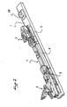
- the figure 2 represents a partial view of one of the skis 1 shown in FIG. figure 1 .
- the fixing device 47 which comprises a front retaining element or abutment 2, a rear retaining element or heel 3, and the trigger device 4 according to the invention.
- the stop 2 is fixed on the ski 1 via a front interface 5.
- the heel 3 is fixed on the ski 1 via a rear interface 6.
- the abutment 2 is a conventional mechanical stop before abutment, that is to say it is triggered when the forces to which it is subjected are greater than the prestressing value of a first spring which is placed in the abutment 2 .
- the rear retaining element is constituted by a conventional mechanical trigger rear heel 3, that is to say that the rear retaining element is triggered when the forces to which it is subjected are greater than the value of prestressing of a second spring which is placed there.
- the front interfaces and / or rear interfaces 6 can be integrated respectively to the stop 2 and / or the heel 3 or integrated in the ski 1.
- the front interface 5 and the rear interface 6 are independent pieces which are fixed on the ski, and on which the stop 2 and the heel 3 are fixed.
- the front retainer, stopper 2 includes a slider in which the body of the front retainer 2 is slidable. It is the sliding of the stop 2 in the slide which constitutes the additional trigger.
- the additional triggering is controlled by the triggering device 4 according to the invention.
- this trigger is added to the two triggers traditionally known in the field of alpine skiing, that is to say the triggering of the stop 2 and the release of the heel 3.
- the additional trigger, controlled by the trigger device according to the invention is a trigger controlled by the electronics.
- Control of the additional device by electronic means offers many advantages over the mechanical trigger. For example, it is possible to provide a trigger which depends on the time during which the forces are applied on the leg of the user. It is also possible to provide a trigger controlled directly by the use, for example by means of a button placed on the handle of the stick or on the ski itself.
- the device of the invention is not limited to being used as a triggering device, which generates an additional trigger to the triggers of the front and rear retention elements. Indeed, we can use the device according to the invention as a single trigger mechanism, for example which would be associated with non-releasable front and rear retention elements such as stirrups.
- the trigger device 4 comprises a housing 8 which is placed on the ski between the front interface 5 and the rear interface 6.
- the figure 3 represents a bottom view of the casing 8 of the trigger device 4.
- the casing 8 is fixed on the ski by means of four screws, not shown on this FIG. 4, which passes through four holes 49 formed on the housing 8.
- the housing 8 comprises a plurality of cavities 56 in which are inserted the various parts and elements constituting the control device 4. These cavities are closed by a cover 7 which is held on the housing by means of six screws, not shown.
- the triggering device comprises a motor 9 placed and retained by wedging in one of the cavities of the housing 8.
- a cam 11 is fixed on the output shaft of the motor 9 and is rotated by the motor 9.
- a lever 12 is placed in another housing cavity 8. It is pivotally mounted relative to the housing with a first pin 50.
- the trigger 10 is also pivotally mounted in the housing via two lugs 52 which are excrescences protruding from the latter and which are received in corresponding seats formed in the housing and in the cover 7.
- the rod 27 is slidably mounted in a cylindrical cavity of the housing.
- the locking device comprises a lock 32 on which is formed a lock cam 34. It also comprises a pawl 16 pivotally mounted relative to the housing with a second pin 51 and a lever 33 for actuation.
- the triggering device 4 also comprises two bars 13 fixed to the casing by means of plates 14 and on which the force sensors 43 may be fixed.
- the electronics of the tripping device 4 is placed on a main plate 36 which is received in one of the cavities of the housing 8.
- the main plate 36 is connected to the motor via a motor cable 39, to the sensor 43 by means of intermediate of a sensor cable 42, and a plate "limit switch" 37 located near the pawl 16 and the trigger 10.
- FIG. figure 4 For the sake of simplicity in explaining the operation of the trigger device 4, it is shown in FIG. figure 4 all the mechanical parts thereof without representing either the electrical elements or the housing.
- the motor 9 has not been shown but the axis around which it rotates, the axis A1 is shown in fine dashed line.
- the cam 11 is also rotatable, as driven by the motor 9, about the axis A1.
- the cam 11 comprises a cylindrical body 54 and a plate 17.
- the plate 17 is traversed by a cam path 18 which takes the form of a groove 19. This groove 19 receives the motor finger 35 of the lever 12.
- the lever 12 is pivotally mounted about an axis A2 shown in the drawing by a thin mixed line, and in fact constituted by a first pin 50.
- the lever 12 comprises a large crank 20, at the end of which is find the motor finger 35, and a small crank 21, at the end of which is the retaining finger 22.
- the motor finger 35 is made by a wire which is inserted into force in a cylindrical cavity of the lever and which protrudes from the lever a distance such that it can come into the groove 19 of the cam 11.
- the retaining finger 22 which is subjected to forces larger than the motor finger 35 is also constituted by a wire inserted into force in a circular cavity of the lever 12, but it also comprises a protrusion 57 of the lever which serves as a support for said wire.
- the metal son used are for example spring strands. They allow very high local support pressures.
- Lever 12 is shown at figure 4 in the closed position. This position corresponds to the position occupied by the trigger device when the shoe is held in the fastener.
- the retaining finger 22 is in contact with the control tooth 24 formed on the trigger 10.
- the contact between the control tooth 24 and the retaining finger is maintained by the pressure of the spring blade 23 which is fixed on the release 10 and bears on one of the walls of the housing 8.
- the trigger 10 is pivotally mounted about an axis A3, which is perpendicular to the axes A1 and A2. It comprises a trigger tooth 25 provided to fit into a notch 28 formed at one end of the rod 27.
- the other end of the rod 27 is not shown in this figure. This other end is connected to the retaining element of the boot which is able to move away so as to effect the release and release of the shoe.
- the retaining element which is able to move away is the stop 2.
- the triggering device also comprises a locking device. The locking device 53 serves to keep the trigger device 4 in the closed state. Thus whatever the conditions measured by the sensor, the trigger 10 can not rock and therefore can not release the rod 27.
- Such a locking device is particularly interesting because if the electric power supply to the electronic control circuit fails, or if the electronic circuit is faulty, there is the risk of inadvertent tripping. Also, the locking device resets the trigger device 4 if the power supply is missing while the device is in the open position. On the other hand, during the procedures for testing the operation of the mechanical releases of the fastening device, ie of the heel piece and the abutment, with a view to checking compliance with the standards or during long storage. duration, it is important to disconnect the additional trigger, so as not to disrupt the verification of compliance with standards.
- the locking device 53 comprises a lock 32 on which is formed a lock cam 33, this lock is actuated by a handle 33 and it acts on the trigger 10 via a pawl 16.
- the pawl 16 is pivotally mounted around an axis A4 materialized by a second pin 51.
- the pawl 16 comprises a first stop 29 intended to come into contact with a locking tooth 26 formed on the trigger 10. It also comprises a second stop 30, an anchor 55 for to a lock spring 31, and disposed on the pawl 16 in opposition, relative to the axis A4 of the second stop 30.
- the spring which works in compression maintains the second stop 30 in contact against the latch cam 34 of the latch 32.
- the lock cam 34 mainly comprises two portions: a "locking" portion and an “unlocking” portion.
- the figure 4 represents the locking device in the "locking" position. In this position the portion of the cam 34 which is in contact with the pawl is the “locking” portion. The pawl 16 is then pushed towards the trigger 10 and thus, the locking tooth 26 is in contact with the first stop 29.
- the trigger 10 is constrained in rotation in the direction S by the leaf spring 23. Thus the locking tooth contact 26 and first stop 29 is perfectly.
- the rod blocks the rotation of the trigger 10 in the direction opposite to the direction S, so that in this locking position of the locking device and closing the trigger device 4 the trigger 10 is locked in rotation in the both directions.
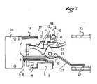
- the figure 5 is a partial view of the trigger device 4 taken from above thereof to represent other elements thereof.
- the main plate 36 supports the electronic equipment of the trigger device 4.
- the latter comprises a printed circuit, an input and output device, which is connected to the acquisition / display module.
- the main plate 36 is connected to the motor 9 via a motor cable 39.
- the main plate 36 is also connected to the sensor 43 formed on the bar 13.
- the main plate 36 is also connected to a plate "end of race 37 located near the locking device 53 and the trigger 10.
- the "limit switch” plate 37 comprises a “limit switch” sensor of the trigger 59, placed in correspondence with the vane of the trigger 40 and a “limit switch” of the pawl 60, placed in correspondence with the vane of the pawl 41.
- the "limit-of-travel” sensors enable the electronic device to know continuously the position of the trigger 10 and the pawl 16.
- the sensor 43 placed on the bar 13 informs the electronic means of the tripping device 4 of the forces to which it is subjected. the shoe, ie the leg of the user.
- the figure 6 is a front view of the plate 17 of the cam 11.
- the plate 17 is traversed by a cam path 18 which takes the form of a groove 19. This groove receives the motor finger 35.
- the cam path is represented by the path made by the middle axis of the motor finger 35.
- the cam path 18 is divided into three distinct and contiguous parts: an initial ramp 44, a tripping ramp 45 and a final ramp 46.
- the initial ramp 44 corresponds to the path followed by the motor finger 35 from its rest position represented by the point C1 on the figure 6 to a position materialized by the point C2.
- This initial ramp is characterized by the fact that it corresponds to an arc of circle centered on the axis A1 and making a radius equal to Rmin.
- This circular arc C1-C2 defines an angular sector of angle ⁇ 1 substantially equal to 130 °.
- the radius of the initial ramp Rmin is very small, especially less than 2 mm.
- the initial ramp 44 is not a constant radius, but rather with a radius that varies very little, for example a radius whose variation between C1 and C2 does not exceed 20%.
- the second part of the cam path 18 is the ramp 45.
- This trigger ramp corresponds to a path of the motor finger 35 between the point C2 placed at a distance Rmin of the axis A1 and a point C3 placed at a distance Rmax of the axis A1.
- the tripping ramp 45 occupies with respect to the axis A1 an angular sector of angle ⁇ 2.
- the locking device In the first, the locking device is in the "locking" position (as shown in FIG. figure 4 ). Although the retaining finger 22 does not prevent the trigger 10 from pivoting in the discharge direction S, the latter does not rotate because it is prevented by the contact between the locking tooth 26 and the first stop 29.
- this first possibility corresponds where it is desired a "conventional" operation of the fastening system, that is to say where only the triggers of the abutment 2 or heel can take place.
- the second possibility corresponds to the normal operation of the triggering device.
- the unlocking device is in the unlocking position and the pawl 16 does not prevent the release from rotating in the discharge direction S.
- the trigger 10 pushed by the leaf spring 23 is driven in the release direction S, the trigger tooth 25 out of the notch 28 and the rod 27 is released.
- the sliding of the rod 27 drives that of the stop 2, which results in the release of the shoe.
- the third part of the cam path 18 is called the final ramp 46. It corresponds to a path of the motor finger 35 between the point C3 and the point C4. It is an arc or a line that is characterized by the fact that it is constant or almost constant radius with respect to the axis A1. It occupies an angular sector of angle ⁇ 3 substantially equal to 10 °.
- the motor finger 35 When the motor finger 35 is in the final ramp, it no longer exerts force on the cam 11 so that the motor is no longer brought to deliver a large torque. Since the torque delivered by an electromagnetic motor is proportional to the current that it consumes, the monitoring of its power consumption makes it possible to know when the motor finger 35 has reached its final position and therefore when to stop power the engine 9.
- the motor 9 is a rotary electromagnetic or other motor that provides a low torque of the order of 1 mN.m (milliNewton.meter).
- the trigger device does not have a gear train on the output shaft of the engine, but it is known that the gear trains consume energy. The reduction of the forces is obtained by a particular arrangement of the lever 12 and the rocker 10.
- the particular arrangement of the lever 12 and the rocker 10 comprises in particular the shape of each of these two parts, the distances between the contact points and the axes of rotation A2 and A3 and the slopes of the contact surfaces between the different parts.
- the length L1 of said large crank is greater than 2 times the length L2 of said small crank, preferably greater than 2.7 times.
- the ratio L1 / L2 is equal to 3.
- the distance D1 separating said control tooth from the axis A3 is greater than 3 times the distance D2 separating said trigger tooth from the axis A3, preferably greater than 3.7 times.
- the ratio D1 / D2 is equal to 5.
- the orientation of the contact surfaces between the parts contributes to the reduction of the forces. This is particularly the case at the link rod / trigger and trigger / lever.
- the figure 8 illustrates the method of determining the slope of the contact surface of the link / trigger link, referred to as the first contact surface 62.
- This pivot connection is provided by two lugs 52 which are received in connection bearings formed in the housing and the cover. . These bearings have a radius R52.
- the slope of the rod / trigger contact is then determined taking into account the coefficient of friction ⁇ 2 between these two parts.
- the direction of the contact force of the rod on the trigger is determined in relation to the normal at the point of contact "rod / trigger" 65. To avoid creating a jamming of the system and a blockage thereof, it must be ensured that the direction of the contact force 65 remains above the circle K1.
- the figure 9 illustrates the method of determining the slope of the contact surface between the trigger and the lever, which contact surface is provided on the control tooth 24.
- the direction of the contact force 66 between the trigger 10 and the lever 12 is determined relative to the normal at the point of contact "trigger / lever" 67 taking into account the coefficient of friction ⁇ 4 of the trigger 10 on the lever 12.
- the slope of the second contact surface 63 is then determined so that the direction of the force of the contact 66 remains outside the circle K2.
- the first check is for conventional front and rear restraints. To do this the user ensures that the lever 33 of the locking device 53 is in the "locking" position. When the locking device is in the locking position the trigger device 4 is inoperative and the user or the technician can adjust the heel 3 or the stop 2.
- these settings include both a length adjustment and the setting of the springs contained in the stop 2 and in the heel 3.
- the acquisition / display module 58 which comprises a display screen and one or more acquisition buttons or a cursor, or any other means of information exchange.
- the acquisition / display module 58 is used for usage checks: is the triggering device turned on, does it have enough energy (the battery is charged), and allows the user to return some data on his technical level of skiing, on the state of the snow.
- the user makes a fast fall forward in the axis of the skis.
- the heel 3 which triggers and releases the shoe
- the user undergoes a rapid torsion of the leg.
- the stop 2 which triggers and releases the shoe.
- the first two cases are conventional triggering situations, in any case the triggering situations are solved by the fixing devices as they are currently known on the market.
- the sensor 43 placed on the bar 13 constantly measures the forces to which the stop is subjected, and through it the efforts to which the shoe and the leg of the user are subjected. The value of these forces is constantly analyzed by the electronic circuit present on the main plate 36.
- the electronic circuit contains the programming of a tripping law which determines as a function of the value of the forces and the time during which they are applied on the user's leg, whether the trigger should be controlled or not.
- the signal is sent to the motor 9.
- the rotation of the motor and the cam causes the lever 12 to tilt until it reaches the open position.
- the lever 12 has reached its open position it no longer exerts any obstruction to the rocker 10, which can pivot in the discharge direction S.
- the rod 27 is released and since it is linked in translation with the stop 2 the forces exerted on the abutment drive the rod 27.
- the stop 2 moves away from the heel and the boot is released.
- the user must reset the fixing device.
- the reset is done by pushing the stopper 2 towards the heel 3. This movement also causes the translation of the rod 27 to the rocker 10, the latter being always in the open position.
- the electronic circuit placed on the main plate 36 is informed of the return of the trigger 10 in its closed position by the limit switch placed on the plate "limit switch", which cooperates with the fin 40 of the trigger.
- the electronic circuit can then feed the motor 9 so that it rotates in the opposite direction bringing the cam 11 back to its initial position.
- the cam 11 places the lever 12 in the closed position and the retaining finger 22 comes into contact with the control tooth 24.
- the trigger device is then returned to the closed position, rearmed, and the user can again put on your skis safely.
- the figure 7 discloses a partial view of a second embodiment of the invention. Only the mobile mechanical elements have been represented in this figure. The housing, the cover and the electronic elements are not represented.
- the motor 9 drives a cam 11.
- the cam 11 comprises a cam path whose initial portion is almost centered on the axis of rotation of the motor A1.
- a lever 12 is pivotally mounted about an axis A2 by means of a first pin 51. This lever comprises a large crank 20 at the end of which is a finger which follows the cam path in the cam 11, and a small crank 21 which when the lever 12 is in the closed position retains a control tooth 24 of the trigger 10.
- the trigger 10 is pivotally mounted about an axis A3 with a second pin 52. Axis A3 is parallel to axis A2 and axis A1.
- a triggering tooth 25 is provided on the trigger 10, it holds the rod 27.
- the figure 10 represents a front view of the cam 11 of the device shown in FIG. figure 7 .
- the cam 11 is traversed by a cam path 18 which takes the form of a groove 19. This groove receives the motor finger 35.
- the cam path is represented by the path made by the axis middle of the motor finger 35.
- the cam path 18 is divided into three distinct and contiguous parts: an initial ramp 44, a tripping ramp 45 and a final ramp 46.
- the initial ramp 44 corresponds to the path followed by the motor finger 35 from its rest position represented by the point C1 on the figure 6 to a materialized position by the point C2.
- This initial ramp is characterized by the fact that it corresponds to an arc of circle centered on the axis A1 and making a radius equal to Rmin.
- This circular arc C1-C2 defines an angular sector of angle ⁇ substantially equal to 130 °.
- the radius of the initial ramp Rmin is very small, especially less than 2 mm.
- the second part of the cam path 18 is the ramp 45.
- This trigger ramp corresponds to a path of the motor finger 35 between the point C2 placed at a distance Rmin of the axis A1 and a point C3 placed at a distance Rmax of the axis A1.
- the tripping ramp 45 occupies with respect to the axis A1 an angular sector of angle ⁇ 2.
- the third part of the cam path 18 is called the final ramp 46. It corresponds to a path of the motor finger 35 between the point C3 and the point C4. It is an arc or a line that is characterized by the fact that it is constant or almost constant radius with respect to the axis A1. It occupies an angular sector of angle ⁇ 3 substantially equal to 10 °.
- the motor finger 35 When the motor finger 35 is in the final ramp, it no longer exerts force on the cam 11 so that the motor is no longer brought to deliver a large torque. Since the torque delivered by an electromagnetic motor is proportional to the current that it consumes, the monitoring of its power consumption makes it possible to know when the motor finger 35 has reached its final position and consequently when to stop power the engine 9.
Landscapes
- Engineering & Computer Science (AREA)
- Mechanical Engineering (AREA)
- Portable Nailing Machines And Staplers (AREA)
- Transmission Devices (AREA)
Applications Claiming Priority (1)
| Application Number | Priority Date | Filing Date | Title |
|---|---|---|---|
| FR0801040A FR2927818B1 (fr) | 2008-02-26 | 2008-02-26 | Dispositif de declenchement pour fixation d'une chaussure sur un engin de glisse |
Publications (1)
| Publication Number | Publication Date |
|---|---|
| EP2095853A1 true EP2095853A1 (de) | 2009-09-02 |
Family
ID=39745549
Family Applications (1)
| Application Number | Title | Priority Date | Filing Date |
|---|---|---|---|
| EP09001887A Withdrawn EP2095853A1 (de) | 2008-02-26 | 2009-02-11 | Auslösevorrichtung für Befestigung eines Schuhs auf einem Snowboard |
Country Status (3)
| Country | Link |
|---|---|
| US (1) | US20090212534A1 (de) |
| EP (1) | EP2095853A1 (de) |
| FR (1) | FR2927818B1 (de) |
Cited By (1)
| Publication number | Priority date | Publication date | Assignee | Title |
|---|---|---|---|---|
| EP2438969A1 (de) | 2010-09-28 | 2012-04-11 | Skis Rossignol | Skibindung mit Sicherheitsschnittstelle |
Families Citing this family (7)
| Publication number | Priority date | Publication date | Assignee | Title |
|---|---|---|---|---|
| US9126098B2 (en) * | 2011-06-10 | 2015-09-08 | Thomas A. Trudel | Releasable snowboard binding |
| US9526971B1 (en) * | 2015-09-18 | 2016-12-27 | Rossland Binding Company | Remote release ski binding |
| CN110913962B (zh) * | 2017-03-14 | 2022-02-08 | 斯托普瑞尔发展有限责任公司 | 处理器控制的雪地运动靴结合 |
| US11040267B2 (en) | 2017-03-14 | 2021-06-22 | Stop River Development LLC | Processor-controlled sport boot binding |
| US10729968B2 (en) | 2018-05-25 | 2020-08-04 | Rossland Binding Company | Remote release snowboard binding |
| CN114096317A (zh) | 2019-02-25 | 2022-02-25 | 斯托普瑞尔发展有限责任公司 | 用于与冰雪运动靴和捆绑系统一起使用的安全机构 |
| IT202100020519A1 (it) * | 2021-07-30 | 2023-01-30 | Petrarca’S Ideas Innovative Startup Srl | Attacco per sci e procedimento di aggancio o sgancio di uno scarpone da detto attacco |
Citations (6)
| Publication number | Priority date | Publication date | Assignee | Title |
|---|---|---|---|---|
| WO1993003804A1 (de) | 1991-08-23 | 1993-03-04 | Htm Sport- Und Freizeitgeräte Gesellschaft M.B.H. | Sicherheitsskibindung |
| WO1993003803A1 (de) * | 1991-08-23 | 1993-03-04 | Htm Sport- Und Freizeitgeräte Gesellschaft M.B.H. | Sicherheitsskibindung |
| WO1995012440A1 (de) | 1993-11-05 | 1995-05-11 | Wilfried Waldner | Auslösevorrichtung für eine skibindung |
| WO2004078282A2 (de) * | 2003-03-04 | 2004-09-16 | Marker Deutschland Gmbh | Auslösbare bindung mit elektronischer steuerung für ski bzw. snowboards |
| EP1810728A1 (de) * | 2006-01-20 | 2007-07-25 | Salomon S.A. | Skibindung für einen Schuh auf einem Ski |
| EP1810727A1 (de) * | 2006-01-20 | 2007-07-25 | Salomon S.A. | Skibindung für Skischuh |
Family Cites Families (18)
| Publication number | Priority date | Publication date | Assignee | Title |
|---|---|---|---|---|
| AT375833B (de) * | 1982-10-19 | 1984-09-10 | Tyrolia Freizeitgeraete | Ausloesemechanismus fuer eine sicherheitsskibindung |
| DE4030816A1 (de) * | 1990-09-28 | 1992-04-02 | Jungkind Roland | Fersenhalterung einer sicherheitsskibindung |
| IT1251777B (it) * | 1991-11-08 | 1995-05-24 | Nordica Spa | Talloniera per attacchi da sci con mezzi di riarmo automatico |
| US5803480A (en) * | 1993-05-27 | 1998-09-08 | Rottefella S.A. | Ski-binding arrangement to fix a ski boot to a ski, in particular a touring or cross-country ski |
| FR2717705B1 (fr) * | 1994-03-24 | 1996-06-07 | Frederic Paradis | Butée avant pour fixation de sécurité de ski alpin. |
| DE19635681A1 (de) * | 1996-09-03 | 1998-03-05 | Marker Deutschland Gmbh | Schuhhalteraggregat |
| DE19636886A1 (de) * | 1996-09-11 | 1998-03-12 | Marker Deutschland Gmbh | Schuhhalteraggregat einer auslösbaren Skibindung |
| US6648365B1 (en) * | 1997-01-08 | 2003-11-18 | The Burton Corporation | Snowboard binding |
| US6623027B1 (en) * | 1998-06-15 | 2003-09-23 | Bryce Wheeler | Release binding and brake for telemark and cross-country skis |
| FR2806639B1 (fr) * | 2000-03-23 | 2002-06-21 | Emery Sa | Perfectionnement pour dispositif de retenue d'une chaussure de ski sur un ski |
| US7104564B2 (en) * | 2000-08-10 | 2006-09-12 | Martin Ralph M | Backwards release ski binding |
| FR2817161B1 (fr) * | 2000-11-28 | 2003-02-28 | Look Fixations Sa | Fixation de securite pour chaussure de ski |
| FR2843037B1 (fr) * | 2002-08-01 | 2006-01-27 | Salomon Sa | Ensemble de retenue d'une chaussure sur une planche de glisse |
| FR2892314B1 (fr) * | 2005-10-20 | 2010-10-15 | Salomon Sa | Fixation de securite |
| US7841614B2 (en) * | 2005-10-25 | 2010-11-30 | Saloman S.A.S. | Safety binding |
| US7458598B2 (en) * | 2005-12-05 | 2008-12-02 | Jeffrey Giffin | Telemark binding with releasable riser plate assembly |
| FR2912663B1 (fr) * | 2007-02-19 | 2009-07-10 | Salomon Sa | Fixation de securite pour chaussure de ski |
| US7954828B2 (en) * | 2008-08-01 | 2011-06-07 | General Electric Company | Caster locking system for medical transport cart |
-
2008
- 2008-02-26 FR FR0801040A patent/FR2927818B1/fr not_active Expired - Fee Related
-
2009
- 2009-02-11 EP EP09001887A patent/EP2095853A1/de not_active Withdrawn
- 2009-02-25 US US12/392,662 patent/US20090212534A1/en not_active Abandoned
Patent Citations (6)
| Publication number | Priority date | Publication date | Assignee | Title |
|---|---|---|---|---|
| WO1993003804A1 (de) | 1991-08-23 | 1993-03-04 | Htm Sport- Und Freizeitgeräte Gesellschaft M.B.H. | Sicherheitsskibindung |
| WO1993003803A1 (de) * | 1991-08-23 | 1993-03-04 | Htm Sport- Und Freizeitgeräte Gesellschaft M.B.H. | Sicherheitsskibindung |
| WO1995012440A1 (de) | 1993-11-05 | 1995-05-11 | Wilfried Waldner | Auslösevorrichtung für eine skibindung |
| WO2004078282A2 (de) * | 2003-03-04 | 2004-09-16 | Marker Deutschland Gmbh | Auslösbare bindung mit elektronischer steuerung für ski bzw. snowboards |
| EP1810728A1 (de) * | 2006-01-20 | 2007-07-25 | Salomon S.A. | Skibindung für einen Schuh auf einem Ski |
| EP1810727A1 (de) * | 2006-01-20 | 2007-07-25 | Salomon S.A. | Skibindung für Skischuh |
Cited By (2)
| Publication number | Priority date | Publication date | Assignee | Title |
|---|---|---|---|---|
| EP2438969A1 (de) | 2010-09-28 | 2012-04-11 | Skis Rossignol | Skibindung mit Sicherheitsschnittstelle |
| US8585074B2 (en) | 2010-09-28 | 2013-11-19 | Skis Rossignol | Boot-attachment device on a ski with safety interface |
Also Published As
| Publication number | Publication date |
|---|---|
| FR2927818A1 (fr) | 2009-08-28 |
| US20090212534A1 (en) | 2009-08-27 |
| FR2927818B1 (fr) | 2011-09-09 |
Similar Documents
| Publication | Publication Date | Title |
|---|---|---|
| FR2927818A1 (fr) | Dispositif de declenchement pour fixation d'une chaussure sur un engin de glisse | |
| EP1810727B1 (de) | Skibindung für Skischuh | |
| EP1958677B1 (de) | Sicherheitsbindung für Skischuhe | |
| FR2518620A1 (fr) | Serrure a pene pivotant, notamment pour vehicule automobile | |
| FR2459099A1 (fr) | Dispositif de commande pour machine-outil | |
| EP0135448A1 (de) | Vorrichtung zur zeitweiligen Entkupplung von zwei koaxial drehenden Teilen | |
| EP1810728B1 (de) | Skibindung für einen Schuh auf einem Ski | |
| FR2857831A1 (fr) | Chaussure de sport, notamment chaussure de ski | |
| EP3542223B1 (de) | System zum sofortantrieb und chronographenmechanismus, der mit einem solchen system ausgestattet ist | |
| FR2849083A1 (fr) | Serrure securisee a deverrouillage mecanique et electrique | |
| CA2059133C (fr) | Dispositif de commande du declenchement temporise d'un mecanisme | |
| EP2189995B1 (de) | Steuerung eines elektrischen Hoch- oder Mittelspannungsgerätes mit einem verbesserten doppelten Einrastmechanismus und entsprechendes Bestückungsverfahren | |
| EP2360534A2 (de) | Gehäuse für Uhrwerk mit automatischem Aufziehmechanismus, das über eine Feststellvorrichtung der Schwungmasse verfügt | |
| FR2808552A1 (fr) | Serrure a deverrouillage mecanique et electrique | |
| CH718458A9 (fr) | Mécanisme d'actionnement pour mouvement horloger, en particulier mécanisme de chronographe comportant un tel mécanisme d'actionnement. | |
| EP2068211B1 (de) | Chronograph-Steuervorrichtung | |
| EP0543966B1 (de) | Absatzfleck einer ski-sicherheitsbindung | |
| CH713117A2 (fr) | Boîte de montre à lunette rotative. | |
| CH708902A2 (fr) | Pièce d'horlogerie à animation. | |
| CH720479B1 (fr) | Dispositif d'embrayage vertical, mécanisme de chronographe, mouvement horloger et pièce d'horlogerie | |
| EP2339414B1 (de) | Chronograph mit einem einzigen Drücker | |
| CH702429A2 (fr) | Chronographe mono-poussoir. | |
| CH712642A2 (fr) | Pièce d'horlogerie comprenant un dispositif de commutation d'un mécanisme horloger. | |
| CH712537A1 (fr) | Mécanisme d'animation. | |
| WO2007118998A2 (fr) | Dispositif de retenue de securite d'une chaussure sur une planche de glisse |
Legal Events
| Date | Code | Title | Description |
|---|---|---|---|
| PUAI | Public reference made under article 153(3) epc to a published international application that has entered the european phase |
Free format text: ORIGINAL CODE: 0009012 |
|
| AK | Designated contracting states |
Kind code of ref document: A1 Designated state(s): AT BE BG CH CY CZ DE DK EE ES FI FR GB GR HR HU IE IS IT LI LT LU LV MC MK MT NL NO PL PT RO SE SI SK TR |
|
| AX | Request for extension of the european patent |
Extension state: AL BA RS |
|
| 17P | Request for examination filed |
Effective date: 20100215 |
|
| 17Q | First examination report despatched |
Effective date: 20100315 |
|
| AKX | Designation fees paid |
Designated state(s): AT BE BG CH CY CZ DE DK EE ES FI FR GB GR HR HU IE IS IT LI LT LU LV MC MK MT NL NO PL PT RO SE SI SK TR |
|
| STAA | Information on the status of an ep patent application or granted ep patent |
Free format text: STATUS: THE APPLICATION IS DEEMED TO BE WITHDRAWN |
|
| 18D | Application deemed to be withdrawn |
Effective date: 20130903 |