EP2095958A1 - Tintenpatrone und System mit einer solchen Tintenpatrone - Google Patents
Tintenpatrone und System mit einer solchen Tintenpatrone Download PDFInfo
- Publication number
- EP2095958A1 EP2095958A1 EP08003698A EP08003698A EP2095958A1 EP 2095958 A1 EP2095958 A1 EP 2095958A1 EP 08003698 A EP08003698 A EP 08003698A EP 08003698 A EP08003698 A EP 08003698A EP 2095958 A1 EP2095958 A1 EP 2095958A1
- Authority
- EP
- European Patent Office
- Prior art keywords
- ink
- case
- front face
- ink cartridge
- ink supply
- Prior art date
- Legal status (The legal status is an assumption and is not a legal conclusion. Google has not performed a legal analysis and makes no representation as to the accuracy of the status listed.)
- Granted
Links
- 238000004891 communication Methods 0.000 claims description 15
- 239000012530 fluid Substances 0.000 claims description 12
- 239000000463 material Substances 0.000 description 8
- 239000011347 resin Substances 0.000 description 6
- 229920005989 resin Polymers 0.000 description 6
- 230000008901 benefit Effects 0.000 description 5
- 230000005484 gravity Effects 0.000 description 4
- 230000007246 mechanism Effects 0.000 description 4
- 230000003287 optical effect Effects 0.000 description 4
- 238000010926 purge Methods 0.000 description 4
- 238000010586 diagram Methods 0.000 description 2
- -1 e.g. Substances 0.000 description 2
- 239000013013 elastic material Substances 0.000 description 2
- 239000007769 metal material Substances 0.000 description 2
- 238000000034 method Methods 0.000 description 2
- 238000012544 monitoring process Methods 0.000 description 2
- 230000008569 process Effects 0.000 description 2
- 238000013459 approach Methods 0.000 description 1
- 239000003086 colorant Substances 0.000 description 1
- 230000008020 evaporation Effects 0.000 description 1
- 238000001704 evaporation Methods 0.000 description 1
- 238000002347 injection Methods 0.000 description 1
- 239000007924 injection Substances 0.000 description 1
- 238000003780 insertion Methods 0.000 description 1
- 230000037431 insertion Effects 0.000 description 1
- 239000007788 liquid Substances 0.000 description 1
- 239000004973 liquid crystal related substance Substances 0.000 description 1
- 238000012986 modification Methods 0.000 description 1
- 230000004048 modification Effects 0.000 description 1
- 239000000049 pigment Substances 0.000 description 1
- 238000012545 processing Methods 0.000 description 1
- 230000001360 synchronised effect Effects 0.000 description 1
- 230000008719 thickening Effects 0.000 description 1
- XLYOFNOQVPJJNP-UHFFFAOYSA-N water Substances O XLYOFNOQVPJJNP-UHFFFAOYSA-N 0.000 description 1
Images


Classifications
-
- B—PERFORMING OPERATIONS; TRANSPORTING
- B41—PRINTING; LINING MACHINES; TYPEWRITERS; STAMPS
- B41J—TYPEWRITERS; SELECTIVE PRINTING MECHANISMS, i.e. MECHANISMS PRINTING OTHERWISE THAN FROM A FORME; CORRECTION OF TYPOGRAPHICAL ERRORS
- B41J2/00—Typewriters or selective printing mechanisms characterised by the printing or marking process for which they are designed
- B41J2/005—Typewriters or selective printing mechanisms characterised by the printing or marking process for which they are designed characterised by bringing liquid or particles selectively into contact with a printing material
- B41J2/01—Ink jet
- B41J2/17—Ink jet characterised by ink handling
- B41J2/175—Ink supply systems ; Circuit parts therefor
- B41J2/17503—Ink cartridges
- B41J2/17553—Outer structure
-
- B—PERFORMING OPERATIONS; TRANSPORTING
- B41—PRINTING; LINING MACHINES; TYPEWRITERS; STAMPS
- B41J—TYPEWRITERS; SELECTIVE PRINTING MECHANISMS, i.e. MECHANISMS PRINTING OTHERWISE THAN FROM A FORME; CORRECTION OF TYPOGRAPHICAL ERRORS
- B41J2/00—Typewriters or selective printing mechanisms characterised by the printing or marking process for which they are designed
- B41J2/005—Typewriters or selective printing mechanisms characterised by the printing or marking process for which they are designed characterised by bringing liquid or particles selectively into contact with a printing material
- B41J2/01—Ink jet
- B41J2/17—Ink jet characterised by ink handling
- B41J2/175—Ink supply systems ; Circuit parts therefor
- B41J2/17503—Ink cartridges
- B41J2/17513—Inner structure
-
- B—PERFORMING OPERATIONS; TRANSPORTING
- B41—PRINTING; LINING MACHINES; TYPEWRITERS; STAMPS
- B41J—TYPEWRITERS; SELECTIVE PRINTING MECHANISMS, i.e. MECHANISMS PRINTING OTHERWISE THAN FROM A FORME; CORRECTION OF TYPOGRAPHICAL ERRORS
- B41J2/00—Typewriters or selective printing mechanisms characterised by the printing or marking process for which they are designed
- B41J2/005—Typewriters or selective printing mechanisms characterised by the printing or marking process for which they are designed characterised by bringing liquid or particles selectively into contact with a printing material
- B41J2/01—Ink jet
- B41J2/17—Ink jet characterised by ink handling
- B41J2/175—Ink supply systems ; Circuit parts therefor
- B41J2/17503—Ink cartridges
- B41J2/1752—Mounting within the printer
-
- B—PERFORMING OPERATIONS; TRANSPORTING
- B41—PRINTING; LINING MACHINES; TYPEWRITERS; STAMPS
- B41J—TYPEWRITERS; SELECTIVE PRINTING MECHANISMS, i.e. MECHANISMS PRINTING OTHERWISE THAN FROM A FORME; CORRECTION OF TYPOGRAPHICAL ERRORS
- B41J2/00—Typewriters or selective printing mechanisms characterised by the printing or marking process for which they are designed
- B41J2/005—Typewriters or selective printing mechanisms characterised by the printing or marking process for which they are designed characterised by bringing liquid or particles selectively into contact with a printing material
- B41J2/01—Ink jet
- B41J2/17—Ink jet characterised by ink handling
- B41J2/175—Ink supply systems ; Circuit parts therefor
- B41J2/17566—Ink level or ink residue control
Definitions
- the present invention relates to an ink cartridge configured to dispense ink onto a recording medium when mounted in an ink jet printer, and a system which uses such an ink cartridge.
- a known inkjet recording system includes an inkjet recording apparatus and a plurality of ink cartridges which are mounted side by side to a mounting portion of the inkjet recording apparatus.
- An ink supply opening is formed at one surface of the ink cartridge, and an ink supply needle is provided in the inkjet recording apparatus and is inserted through the ink supply opening when the ink cartridge is mounted to the inkjet recording apparatus, which causes ink within the ink cartridge to be supplied to inkjet recording apparatus.
- the ink cartridge includes a case and a bag disposed within the case. The bag has a port for supplying ink within the bag to the outside of the bag, and the port is aligned with the ink supply opening.
- a lid, a valve, and a spring are positioned within the port, such that the spring urges the valve to contact the lid.
- the valve contacts the lid fluid communication between the inside of the bag and the outside of the ink cartridge is prevented, and when the ink supply needle applies a predetermined amount of force to the valve greater than and against the urging force of the spring, the valve separates from the lid, and the inside of the bag and the outside of the ink cartridge are in fluid communication with each other.
- Such a known inkjet recording system is described in JP-A-2005-238815 for example.
- Ink may adhere to the ink supply needle after the ink supply needle is inserted into the ink cartridge through the ink supply opening.
- the ink which adheres to the ink supply needle adheres adjacent to the ink supply opening when the ink cartridge is removed from the mounting portion.
- the ink may drip from the ink supply opening or the needle, or both, onto the mounting portion.
- the mounting portion becomes dirtied.
- the new ink cartridge also may become dirtied.
- a hand of user also may become dirtied with ink.
- Another known ink cartridge includes an ink supply portion protruding from one surface of the ink cartridge.
- An ink supply opening is formed at the end of the ink supply portion. Ink also may drip from the ink supply opening of this type of ink cartridge onto a mounting portion of an inkjet recording apparatus.
- Yet another known ink cartridge is configured to be mounted to a mounting portion of another known recording apparatus, and the mounting portion includes a door which is configured to be opened and closed. After this known ink cartridge is mounted to the mounting portion and the door is closed, the door is configured to latch on to the ink cartridge to remove the ink cartridge from the mounting portion when the door is opened by a user, which increases the ease with which the ink cartridge may be removed from the mounting portion.
- a known ink cartridge is described in US 2007/0070140 Al for example. Nevertheless, the user relies on the recording apparatus to remove the ink cartridge from the recording apparatus.
- a technical advantage of the present invention is that the ink cartridge may prevent ink from dripping from the ink cartridge or reduce an amount of ink which drips from the ink cartridge.
- Another technical advantage of the present invention is that the ink cartridge readily may be removed from the recording apparatus.
- an ink cartridge comprises a case, an ink supply portion, an air intake portion, and at least one resilient member.
- the case comprises a front face and a rear face opposite the front face.
- the case has at least a portion of an ink chamber defined therein, and the ink chamber is configured to store ink therein.
- the ink supply portion is positioned at the front face of the case.
- the ink supply portion is configured to dispense ink from an interior of the ink chamber to an exterior of the ink chamber, and the air intake portion is positioned at the case.
- the air intake portion is configured to draw air into the ink chamber.
- the at least one resilient member has a first portion positioned at the front face of the case, and a second portion which is positioned a predetermined distance away from the front face of the case in a predetermined direction away from the ink chamber.
- the resilient member extends from the front face of the case further than the ink supply portion in the predetermined direction.
- the resilient member extends from the front face of the case further than the ink supply portion, when ink drips from the ink supply portion, the resilient member may receive the ink when the ink cartridge is oriented in a particular direction. Moreover, the ink cartridge readily may be removed from a recording apparatus when the resilient member expands. Furthermore, when the ink cartridge is dropped, the resilient member may contact a surface and may absorb the impact. The ink cartridge thus may be protected.
- the ink supply portion may extend from the front face of the case in the predetermined direction. Because the resilient member extends from the front face of the case further than the ink supply portion, even if the ink supply portion extends from the front face of the case, the resilient member may receive dripping ink. Moreover, because the resilient member extends from the front face of the case further than the ink supply portion, when the ink cartridge is dropped, the resilient member may contact a surface and the ink supply portion may not contact the surface. The ink supply portion thus may be protected
- the ink supply portion may comprise an end positioned a particular distance away from the front face of the case in the predetermined direction, and an ink supply opening may be formed at the end of the ink supply portion, wherein the resilient member may extend from the front face of the case further than the end of the ink supply portion in the predetermined direction. Because the resilient member may extend from the front face of the case further than the end of the ink supply portion, when ink drips from the ink supply opening formed at the end of the ink supply portion, the resilient member may receive the ink.
- the ink cartridge may comprise a first resilient member and a second resilient member which are configured to expand and to contract in a same direction as each other. Therefore, even if the first resilient member fails to receive ink, the second resilient member may receive ink. Moreover, the ink cartridge more readily may be removed from a recording apparatus when the first and second resilient members expand. Furthermore, when the ink cartridge is dropped, even if the first resilient member fails to contact a surface, the second resilient member may contact the surface. In another situation, both of the first and second resilient members may contact the surface. The ink cartridge thus may be protected.
- the ink supply portion may be positioned between the first resilient member and the second resilient member. With this configuration, the ink supply portion more readily may be protected.
- the ink cartridge further may comprise a translucent portion positioned at the front face of the case between the second resilient member and the ink supply portion.
- the translucent portion may extend away from the ink chamber, and have an inner space formed therein.
- the inner space may be configured to be in fluid communication with the ink chamber.
- the ink cartridge also may comprise a movable member positioned within the inner space.
- the movable member may be configured to move within the inner space based on an amount of ink in the ink chamber. With this configuration, whether the ink chamber stores a sufficient amount of ink may be detected.
- the resilient member may contact a surface and the translucent portion may not contact the surface. The translucent portion thus may be protected.
- the at least one resilient member may be at least one coil spring, and the case further may comprise a bottom face connected to each of the front face and the rear face, wherein the at least one coil spring may be positioned between the ink supply portion and the bottom face.
- the coil spring may receive and retain ink between adjacent loops via a capillary force.
- the first portion of the at least one resilient member may be unaligned with each of the ink supply portion and the air intake portion in the predetermined direction.
- a system comprises an ink cartridge and an inkjet printer.
- the ink cartridge comprises a case, an ink supply portion, a first conductive coil, and a second conductive coil spring.
- the case comprises a front face and a rear face opposite the front face.
- the case has at least a portion of an ink chamber defined therein, and the ink chamber is configured to store ink therein.
- the ink supply portion is positioned at the front face of the case.
- the ink supply portion is configured to dispense ink from an interior of the ink chamber to an exterior of the ink chamber.
- the first conductive coil spring has a first portion positioned at the front face of the case, and a second portion which is positioned a predetermined distance away from the front face of the case in a predetermined direction.
- the first conductive coil spring is configured to be electrically connected to ink in the ink chamber.
- the second conductive coil spring has a first portion positioned at the front face of the case, and a second portion which is positioned a predetermined distance away from the front face of the case in the predetermined direction.
- the second conductive coil spring is configured to be electrically connected to ink in the ink chamber.
- the inkjet printer comprises a first electric terminal, a second electric terminal, and a determining portion. The first electric terminal is configured to contact the first conductive coil spring.
- the second electric terminal is configured to contact the second conductive coil spring.
- the determining portion is configured to determine an amount of ink disposed in the ink chamber based on an electric resistance between the first electric terminal and the second electric terminal. With this configuration, an amount of ink disposed in the ink chamber may be determined.
- Fig. 1 is a schematic diagram of an inkjet printer and an ink cartridge, according to an embodiment of the present invention.
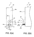
- Fig. 2(a) is a front view of the ink cartridge of Fig 1 .
- Fig. 2(b) is a partial, side view of the ink cartridge of Fig. 1 .
- Fig. 3(a) is a partial, cross-sectional view of the ink cartridge taken along III-III line in Fig. 2(a) and a mounting portion, according to an embodiment of the present invention, just before mounting of the ink cartridge to the mounting portion is completed.
- Fig. 3(b) is a partial, cross-sectional view of the ink cartridge taken along III-III line in Fig. 2(a) and the mounting portion, after the mounting of the ink cartridge to the mounting portion is completed.
- Fig. 4(a) is a cross-sectional view of the ink cartridge taken along III-III line in Fig. 2(a) and the mounting portion, after the mounting of the ink cartridge to the mounting portion is completed and when a sufficient amount of ink is stored in the ink cartridge.
- Fig. 4(b) is a cross-sectional view of the ink cartridge taken along III-III line in Fig. 2(a) and the mounting portion, after the mounting of the ink cartridge to the mounting portion is completed and when the amount of ink stored in the ink cartridge is less than a sufficient amount of ink.
- Fig. 5 is a block diagram of a controller of the ink jet printer of Fig. 1 .
- Fig. 6 is a side view of a coil spring of the ink cartridge of Fig. 1 .
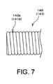
- Fig. 7 is a side view of a coil spring of an ink cartridge, according to another embodiment of the present invention.
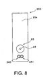
- Fig. 8 is a front view of an ink cartridge, according to yet another embodiment of the present invention.
- Fig. 9 is a front view of an ink cartridge, according to still another embodiment of the present invention.
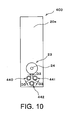
- Fig. 10 is a front view of an ink cartridge, according to still yet another embodiment of the present invention.
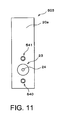
- Fig. 11 is a front view of an ink cartridge, according to a further embodiment of the present invention.
- Fig. 12(a) is a front view of an ink cartridge, according to yet a further embodiment of the present invention.
- Fig. 12(b) is a side view of the ink cartridge of Fig. 12(a) .
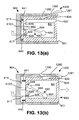
- Fig. 13(a) is a cross-sectional view of the ink cartridge taken along XIII-XIII line of Fig. 12(a) mounted to a mounting portion, according to yet a further embodiment of the present invention when a sufficient amount of ink is stored in the ink cartridge.
- Fig. 13(b) is a cross-sectional view of the ink cartridge being ejected from the mounting portion of Fig. 13(a) when that amount of ink stored in the ink cartridge is less than a sufficient amount of ink.
- Fig. 14 is a partial, side view of an ink cartridge, according to still a further embodiment of the present invention.
- Fig. 15 is a partial, side view of an ink cartridge, according to still another embodiment of the present invention.
- an inkjet printer 1 comprises an inkjet head 2, a mounting portion 4, a flexible tube 10, a carriage 5, a feeding mechanism 6, and a purge device 7.
- Inkjet head 2 also comprises a plurality of nozzles 2a configured to eject ink toward a sheet of paper P, and mounting portion 4 is configured to receive an ink cartridge 3.
- Inkjet head 2 and ink cartridge 3 are in fluid communication with each other through tube 10 when ink cartridge 3 is mounted to mounting portion 4.
- Carriage 5 is configured to reciprocate with inkjet head 2
- feeding mechanism 6 is configured to feed a sheet of paper P
- purge device 7 is configured to draw out air or thickened ink from the inside of inkjet head 2.
- inkjet head 2 reciprocates with carriage 5 in a direction which is perpendicular to a paper plane of Fig. 1 , and a sheet of paper P is fed by feeding mechanism 6 in a horizontal direction in Fig. 1 .
- Inkjet head 2 faces the sheet of paper P, and the reciprocation of inkjet head 2 and feeding of recording paper P are synchronized by a controller 8 (See Fig. 5 ).
- controller 8 See Fig. 5
- Inkjet head 2 ejects ink from nozzles 2a, and ink is supplied from ink cartridge 3 through tube 10.
- Nozzles 2a are positioned higher than mounting portion 4 and ink cartridge 3 to prevent ink leakage from nozzles 2a when printing is not performed.
- Purge device 7 comprises a cap 7a and a pump 7b.
- Cap 7a is configured to selectively move toward and away from an ink-eject surface of inkjet head 2.
- Nozzles 2a are positioned at the ink-eject surface
- cap 7a is configured to cover the ink-eject surface
- pump 7b is configured to draw out ink from nozzles 2a.
- inkjet head 2 is positioned out of a printable area
- cap 7a may cover the ink-eject surface and pump 7b may draw out air or thickened ink from nozzles 2a.
- the printable area is defined as an area where inkjet head 2 ejects ink toward a sheet of paper P. Evaporation of water from ink may result in thickening ink in nozzles 2s, and the purge operation restores ink-eject performance of inkjet head 2.
- Mounting portion 4 opens to the right in Fig. 1 .
- Ink cartridge 3 is configured to be inserted and mounted horizontally into the inside of mounting portion 4 from the opening.
- An ink cartridge 3 is configured to be removed from mounting portion 4 by pulling out a right edge of ink cartridge 3 to the right in Figure 1 .
- ink cartridge 3 comprises a case 20 storing ink and an ink supply portion 23 configured to supply ink from the interior of case 20 to the exterior of case 20.
- Case 20 comprises a front face 20a, and when ink cartridge 3 is mounted to mounting portion 4, front face 20a faces a closed end surface 14 of mounting portion 4 positioned opposite from the opening of mounting portion 4.
- Ink supply portion 23 is positioned at front face 20a.
- Case 20 has a substantially rectangular parallelepiped shape having front face 20a, a rear face 20b opposite front face 20a, a top face, a bottom face opposite the top face, a right side face, and a left side face opposite the right side face.
- Each of the top face and the bottom face is connected to front face 20a and rear face 20b, and each of the right side face and the left side face is connected to front face 20, rear face 20b, the top face, and the bottom face.
- Front face 20a, rear face 20b, the top face, the bottom face, the right side face, and the left side face are substantially parallel to its opposing face, and substantially perpendicular to the other faces.
- Case 20 has a depth between front face 20a and rear face 20b, a height between the top face and the bottom face, and a width between the right side face and the left side face. Case 20 is formed of at least one resin material. Case 20 comprises an ink chamber 21 configured to store ink, e.g., conductive ink comprising coloring agent e.g., dye or pigment, or both. In cartridge 3 is inserted and mounted to mounting portion 4 in a direction parallel to the depth direction of case 20.
- ink e.g., conductive ink comprising coloring agent e.g., dye or pigment, or both.
- Air intake hole 22 is formed through rear face 20b. Air intake hole 22 is positioned adjacent to the upper end of rear face 20b. Before ink cartridge 3 is used, a sticker (not shown) is adhered to rear face 20b to cover air intake hole 22, and fluid communication between the interior of ink chamber 21 and the exterior of the ink chamber 21 via air intake hole 22 is prevented. When a user intends to use ink cartridge 3, the user removes the sticker from rear face 20b, and thereby the interior of ink chamber 21 is brought into fluid communication with the exterior of ink chamber 21 via air intake hole 22.
- Ink supply portion 23 has a cylindrical shape and extends a particular distance from front face 20a in the depth direction of case 20 away from ink chamber 21, and ink supply portion 23 extends substantially perpendicular to front face 20a.
- Ink supply portion 23 has a circular end 23a positioned the particular distance away from front face 20a, and end 23a has an ink supply opening 24 formed at the center thereof.
- Ink supply portion 23 has a cylindrical hole 25 formed therethrough. Hole 25 extends from ink chamber 21 to ink supply opening 24. Hole 25 comprises a first portion 29 connected to ink supply opening 24 and a second portion 30 connected to ink chamber 21. The diameter of first portion 29 is less than the diameter of second portion 30. First portion 29 and second portion 30 are connected via a step surface 31.
- a cylindrical seal member 26 is fitted in first portion 29 of hole 25 adjacent to ink supply opening 24.
- Seal member 26 is formed of an elastic material, e.g., rubber.
- a valve disc 27 and a coil spring 28 are positioned in second portion 30 of hole 25.
- Coil spring 28 is positioned closer to ink chamber 21 than valve disc 27 is positioned to ink chamber 21, and valve disc 27 is urged by coil spring 28 to contact step surface 31.
- the diameter of valve disc 27 is greater than the diameter of first portion 29 of hole 25, and is slightly less than the diameter of second portion 30 of hole 25. Therefore, when valve disc 27 contacts step surface 31, fluid communication between the interior of ink chamber 21 and the exterior of ink cartridge 3 via hole 25 is prevented.
- valve disc 27 separates from step surface 31, and fluid communication between the interior of ink chamber 21 and the exterior of ink cartridge 3 via hole 25 is allowed.
- ink supply tube 17 is inserted into hole 28 and pushes valve disc 27 toward ink chamber 21, ink disposed in ink chamber 21 is supplied to the exterior of ink cartridge 3 via hole 25 and ink supply tube 17.
- Front face 20a has an upper end connected to the top face of case 20 and a lower end connected to the bottom face of case 20.
- At least one resilient member e.g., coil springs 40 and 41
- Coil springs 40 and 41 are positioned on front face 20a between ink supply portion 23 and the lower end of front face 20a, and is configured to expand and contract in the depth direction of case 20.
- Coil springs 40 and 41 have the same shape and are formed of the same conductive metal material. Coil springs 40 and 41 extend a predetermined distance from front face 20a in the depth direction of case 20 away from ink chamber 21, and coil springs 40 and 41 extend substantially perpendicular to front face 20a. Coil springs 40 and 41 are configured to receive ink which drips from ink supply opening 24.
- Coil springs 40 and 41 are separated from each other aligned in the width direction of case 20.
- Coil springs 40 and 41 have ends 40a and 41b, respectively, which are positioned the predetermined distance away from the front face 20a in the depth direction of case 20 away from ink chamber 21.
- Coil springs 40 and 41 extend from front face 20a further than ink supply portion 23 extends from front face 20a in the depth direction of case 20 away from ink chamber 21, such that each of ends 40a and 41a of coil springs 40 and 41 are positioned further from front face 20a than end 23a of ink supply portion 23 is positioned from front face 20a.
- each of coil springs 40 and 41 is formed by coiling a wire, and each of coil springs 40 and 41 has a central axis and is coiled around the central axis.
- the central axis is parallel with the depth direction of case 20. Adjacent portions of each of coil springs 40 and 41 in the central axis direction are separated by a distance D2.
- Distance D2 is selected, such that when coils springs 40 and 41 receives ink which dripped from ink supply opening 24, the adjacent portions of coils springs 40 and 41 retain the ink therebetween via a capillary force.
- distance D2 is less than or equal to about 0.5 millimeters.
- coil springs 40 and 41 are positioned symmetrically with respect to a plane which intersects the center of ink supply opening 24, and is perpendicular to the width direction of case 20. Consequently, the midpoint of the line segment which connects the central axes of coil springs 40 and 41 in the width direction is positioned directly below the center of ink supply opening 24.
- a distance D1 between coil springs 40 and 41 is selected, such that when ink drips from ink supply opening 24 and lands between coil springs 40 and 41, coil springs 40 and 41 retain the ink therebetween via a capillary force.
- distance D1 is less than or equal to about 3.0 millimeters.
- each of ends 40a and 41a of coil springs 40 and 41 is wound in a direction perpendicular to the depth direction of case 20, such that the terminal end of each of ends 40a and 41a does not protrude in the depth direction of case 20.
- Ink cartridge 3 further comprises at least one electrode wire 50, e.g., two electrode wires 50. Ends of electrode wires 50 are connected to the ends of coil springs 40 and 41, respectively. The other ends of electrode wires 50 reach ink chamber 21, respectively.
- ink cartridge 3 may not comprise electrode wires 50.
- the ends of coil springs 40 and 41 may reach ink chamber 21, respectively, and coil springs 40 and 41 may be electrically connected via ink in ink chamber 21.
- a cylindrical ink supply tube 17 is positioned at closed end surface 14 of mounting portion 4. Closed end surface 14 comprises a cylindrical recess 16 and ink supply tube 17 extending from the bottom of recess 16 towards the opening of mounting portion 4.
- ink supply portion 23 fits in recess 16, and ink supply tube 17 is inserted into hole 25 via ink supply opening 24.
- the depth of recess 22 is greater than or equal to the length of ink supply portion 23 extending from front face 20a to end 23a.
- Ink supply tube 17 comprises an end surface 17a, and a cut-out is formed in end surface 17a.
- Mounting portion 4 comprises an outer surface 13 and joint portion 12 positioned at outer surface 13. Tube 10 is connected to joint portion 12. A communication hole 15 is formed through a wall of mounting portion 4, and communication hole 15 is connected to ink supply tube 17 at one end and connected to joint portion 12 at the other end.
- Closed end surface 14 comprises two cylindrical recesses 18 formed therein, and when ink cartridge 3 is mounted to mounting portion 4, coil springs 40 and 41 are accommodated in recesses 18, respectively.
- the diameters of recesses 18 are slightly greater than the outer diameters of coil springs 40 and 41, respectively, and the depths of recesses 18 are slightly less than or equal to the lengths of coils springs 40 and 41, respectively.
- Two electric terminals 19 are disposed at the bottoms of two recesses 18, respectively.
- ends 40a and 41 a of coil springs 40 and 41 contact electric terminals 19, respectively.
- Electric resistance between electric terminals 19 when ink chamber 21 includes a sufficient amount of ink is different than electric resistance between electric terminals 19 when ink chamber 21 does not include a sufficient amount of ink.
- Controller 8 determines whether ink chamber 21 includes a sufficient amount of ink based on the electric resistance between electric terminals 19.
- controller 8 comprises a central processing unit (CPU), a read only memory (ROM), and a random access memory (RAM).
- CPU executes programs to control the respective operations of inkjet printer 1.
- ROM stores programs used by the CPU.
- RAM is a storage area or a work area for temporarily storing the respective data used by the CPU for executing the programs.
- Controller 8 comprises a print controlling portion 110 for controlling the printing operation of inkjet printer 1, i.e., for controlling inkjet head 2, carriage 5, feeding mechanism 6, and the like based on data input from an input device 101, e.g., a computer.
- Controller 8 is electrically connected to electric terminals 19.
- Controller 8 comprises a determining portion 111 for monitoring the electric resistance between electric terminals 19 and determining whether ink chamber 21 includes a sufficient amount of ink based on the electric resistance. When the electric resistance is less than a predetermined resistance, determining portion 111 determines that ink chamber 21 includes a sufficient amount of ink, and when the electric resistance is greater than or equal to the predetermined resistance, determining portion 111 determines that the ink chamber 21 does not include a sufficient amount of ink. Determining portion 111 also controls a display device 9 e.g., a Liquid Crystal Display, a lamp, or the like to indicate whether ink chamber 21 includes a sufficient amount of ink.
- a display device 9 e.g., a Liquid Crystal Display, a lamp, or the like to indicate whether ink chamber 21 includes a sufficient amount of ink.
- ink supply tube 17 is inserted into hole 25, and end surface 17a applies a force to valve disc 27 against the urging force of coil spring 28 to separate valve disc 27 from step surface 31.
- Ink flows from ink chamber 21 into ink supply tube 17 via a cut-out formed in end surface 17a. Ink then flows from ink supply tube 17 to inkjet head 2 via communication hole 15, joint portion 12, and tube 10.
- ink supply tube 17 is removed from hole 25, and valve disc 27 is moved by coil spring 28 to contact step surface 31.
- valve disc 27 moves to step surface 31, ink may be pushed out of second portion 30 of hole 25 to ink supply opening 24.
- ink adhering to ink supply tube 17 may be transferred to end 23a of ink supply portion 23. Consequently, ink may drip from ink supply opening 24 or end 23a of ink supply portion 23, or both.
- coil springs 40 and 41 Ink which drips from ink supply opening 24 or an end 23a of ink supply portion 23, or both, is received by coil springs 40 and 41.
- coil spring 40 or coil spring 41, or both retains ink between adjacent loops via a capillary force
- coil springs 40 and 41 retains ink therebetween via a capillary force, or both.
- ink cartridge 3 may be prevented from being damaged.
- an ink cartridge comprises coil springs 140 and 141 instead of coil springs 40 and 41. Adjacent loops of each of coil springs 140 and 141 contact each other without gaps therebetween. Valleys 140b and 141b are formed between adjacent loops of each of coil springs 140 and 141, respectively. Coil springs 140 and 141 retain ink within valleys 140b via a capillary force. The greater the diameters of the wire of coil springs 140 and 141 are, the deeper the valleys 140b and 141b are, and the deeper valleys 140b and 141b are configured to retain more ink.
- an ink cartridge 203 comprises coil springs 240 and 241 instead of coil springs 40 and 41.
- Coil springs 240 and 241 are aligned in the width direction of case 20 and contacts each other, such that there is no gap between could springs 240 and 241.
- Coil springs 240 and 241 retains ink between adjacent loops of each of coil springs 240 and 241.
- Coil springs 240 and 241 may be the same type of coil spring as coil springs 40 and 41 or coil springs 140 and 141.
- an ink cartridge 303 according to still another embodiment of the present invention comprises a single coil spring 340 instead of coil springs 40 and 41.
- Coil spring 340 is positioned vertically below ink supply portion 23.
- Coil spring 340 retains ink between adjacent loops of coil spring 340.
- an ink cartridge 403 comprises three coil springs 440, 441, and 442 instead of coil springs 40 and 41.
- Coils springs 440 and 441 are positioned between ink supply portion 23 and the lower end of front face 20a.
- Coil springs 440 and 441 are aligned in the width direction of case 20, and are positioned symmetrically with respect to a plane which intersects the center of ink supply opening 24 and is perpendicular to the width direction of case 20.
- Coil spring 442 is positioned between coil springs 440 and 441 and the lower end of front face 20a.
- Coil spring 442 intersects the plane which intersects the center of ink supply opening 24 and is perpendicular to the width direction of case 20.
- Coil springs 440, 441, and 442 are separated from each other by an equal distance D3.
- Coil spring 440, coil spring 441, or coil spring 442, or any combination thereof retains ink between adjacent loops via a capillary force, or coil springs 440, 441, and 442 retain ink therebetween via a capillary force, or both.
- an ink cartridge 503 comprises coil springs 540 and 541 instead of coil springs 40 and 41.
- Coil spring 540 is positioned vertically below ink supply portion 23, and coil spring 541 is positioned vertically above ink supply portion 23.
- Coil spring 540 retains ink which drips from ink supply opening 24 or end 23a of ink supply portion 23, or both, when ink cartridge 503 is removed from mounting portion 4.
- Coil spring 541 retains ink which drips from ink supply opening 24 and or end 23a of ink supply portion 23, or both, when ink cartridge 503 is oriented upside down after ink cartridge 503 is removed from mounting portion 4.
- an ink cartridge 603 according to yet a further embodiment of the present invention comprises a case 620 storing ink, and an ink supply portion 623 configured to supply ink from the interior of case 620 to the exterior of case 620.
- Case 620 has a substantially rectangular parallelepiped shape having a front face 620a, a rear face 620b opposite front face 620a, a top face 620c, a bottom face 620d opposite top face 620c, a right side face, and a left side face opposite the right side face.
- top face 620c and bottom face 620d is connected to front face 620a and rear face 620b, and each of the right side face and the left side face is connected to front face 620a, rear face 620b, top face 620c, and bottom face 620d.
- Front face 620a, rear face 620b, top face 620c, bottom face 620d, right side face, and left side face are substantially parallel to its opposing face, and substantially perpendicular to the other faces.
- Case 620 has a depth between front face 620a and rear face 620b, a height between top face 620c and bottom face 620d, and a width between the right side face and the left side face.
- Case 620 is formed of at least one translucent resin material, e.g., a transparent resin material or a semi-transparent resin material, to allow light to pass therethrough.
- Case 620 comprises an ink chamber 621 configured to store ink.
- Ink supply portion 623 is positioned at front face 620a.
- Top face 620c has a latching recess 600 formed therein.
- Air intake hole 622 is formed through rear face 620b. Air intake hole 622 is positioned adjacent to the upper end of rear face 620b. Before ink cartridge 603 is used, a sticker (not shown) is adhered to rear face 620b to cover air intake hole 622, and the sticker prevents fluid communication between the interior of ink chamber 621 and the exterior of the ink chamber 621 via air intake hole 622. When a user intends to use ink cartridge 603, the user removes the sticker from rear face 620b, and thereby the interior of ink chamber 621 is brought into fluid communication with the exterior of ink chamber 621 via air intake hole 622.
- Ink supply portion 623 has a cylindrical hole 625 formed through a wall of ink cartridge 603, and cylindrical hole 625 extends from front face 620a to ink chamber 621 in the depth direction of case 620.
- a cylindrical seal member 626 is fitted in hole 625.
- Seal member 626 is formed of an elastic material, e.g., rubber.
- Seal member 626 has a hole 624 formed therethrough.
- Ink disposed in ink chamber 621 is supplied to the exterior of ink cartridge 603 via ink supply tube 617. Because seal member 626 contacts the outer surface of ink supply tube 617 tightly, ink is prevented from leaking between ink supply tube 617 and hole 624.
- Case 620 comprises a translucent portion 639 positioned at front face 620a and extending away from ink chamber 621. Whether ink chamber 621 includes a sufficient amount of ink is optically or visually detected through the translucent portion 639.
- Translucent portion 639 is integral with case 620, and is formed of the same material as case 620, e.g., translucent portion 639 is formed of a translucent resin material to allow light to pass therethrough.
- Translucent portion 639 is irradiated with light emitted from an optical sensor 6103.
- Translucent portion 639 comprises a front wall 639a which is flush with front wall 620a, and a pair of side walls 639b extending from front wall 639a towards ink chamber 621. The width of front wall 639a is less than the width of front face 620a.
- Translucent portion 639 has an inner space 646 formed therein, which is defined by front wall 639a and the side walls 639b. Inner space 646 is in fluid communication with ink chamber 621.
- Ink cartridge 603 comprises a movable member, e.g., a pivotable member 660, disposed in ink chamber 621.
- Pivotable member 660 is used in determining whether the amount of ink stored in the ink chamber 621 is greater than or equal to a sufficient amount of ink.
- Pivotable member 660 comprises an indicating portion 662 at one end thereof, and a float portion 664 at the other end thereof.
- Pivotable member 660 also comprises a shaft 666 positioned between and connected to indicating portion 662 and float portion 664. Shaft 666 extends in the width direction of case 620, and shaft 666 is supported by supporting portions disposed on inner surfaces of walls defining side faces of case 620, such that pivotable member 660 pivots about shaft 666.
- Indicating portion 662 is configured to move between a first position within inner space 646 and a second position, e.g., a position within inner space 646. When indicating portion 662 is at the first position, indicating portion 662 contacts a bottom surface of translucent portion 639 as indicated in Fig. 13(a) . When indicating portion 662 is at the second position, indicating portion 662 is separated from the bottom surface of translucent portion 639 as indicated in Fig. 13(b) .
- the specific gravity of float portion 664 is less than the specific gravity of ink stored in the ink chamber 621.
- Float portion 664 has a hollow formed therein, and floats on liquid, such that the float portion 664 moves upward and downward based on the amount of ink within the ink chamber 621, and pivotable member 660 pivots based on the movement of float portion 664.
- float portion 664 may not have the hollow formed therein, and may be formed of a material having a specific gravity less than the specific gravity of ink.
- Indicating portion 662 is configured to indicate whether the amount of ink in the ink chamber 621 is greater than or equal to a sufficient amount of ink.
- indicating portion 662 contacts the bottom surface of translucent portion 639, such that further movement of pivotable member 660 is prevented and indicating portion 662 remains at the first position.
- pivotable member 660 pivots clockwise in Figs. 13(a) and 13(b)
- indicating portion 662 moves away from the bottom surface of the translucent portion 639.
- float portion 664 contacts a bottom surface of the ink chamber 621, further movement of pivotable member 660 is prevented and indicating portion 662 remains at the second position apart from the bottom surface of translucent portion 639.
- Pivotable member 660 comprises a first portion extending from shaft 666 to indicating portion 662, and a second portion extending from shaft 666 to float portion 664.
- the mass of the first portion of pivotable member 660 is less than the mass of the second portion of pivotable member 660. Therefore, the second portion of pivotable member 660 is heavier than the first portion of pivotable member 660 in air. Accordingly, when the amount of ink in ink chamber 621 approaches an insufficient amount of ink, pivotable member 660 pivots clockwise about shaft 666 in Figs. 13(a) and 13(b) and indicating portion 662 separates from the bottom surface of translucent portion 639.
- ink chamber 621 includes an amount of ink which is less than a sufficient amount of ink.
- Front face 620a has an upper end connected to top face 620c and a lower end connected to bottom face 620d.
- a coil spring 640 is positioned on front face 620a between ink supply portion 623 and the lower end of front face 620a.
- Translucent portion 639 is positioned between the upper end of front face 620a and ink supply portion 623.
- a coil spring 641 is positioned on front face 620a between the upper end of front face 620a and translucent portion 639.
- Coil springs 640 and 641 are substantially the same as coil springs 40 and 41, respectively.
- Coil springs 640 and 641 are formed of the same metal material. Coil springs 640 and 641 are coupled to front face 620a at one ends.
- coil springs 640 and 641 are coupled to front face 620a by direct contact between coil springs 640 and 641 and front face 620a, or by indirect contact between coil springs 640 and 641 and front face 620a, i.e., with at least one other element positioned between coil springs 640 and 641 and front face 620a.
- Coil springs 640 and 641 extend a predetermined distance from front face 620a in the depth direction of case 620 away from ink chamber 621, and extend substantially perpendicular to front face 620a.
- Coil springs 640 and 641 intersect a plane which intersects the center of hole 624 and is perpendicular to the width direction of case 620.
- Coil springs 640 and 641 have ends 640a and 641b, respectively, which are positioned the predetermined distance away from the front face 620a in the depth direction of case 620 away from ink chamber 621. Coil springs 640 and 641 extend from the front face 620a further than ink supply portion 623 in the depth direction of case 620 away from ink chamber 621, such that each of ends 640a and 641a of coil springs 640 and 641 is positioned further from front face 620a than ink supply portion 623 is positioned from front face 620a.
- Mounting portion 604 has an opening 601 formed therethrough, and ink cartridge 603 is configured to be inserted and mounted horizontally into the inside of mounting portion 604 through opening 601 in a direction parallel to the depth direction of case 620.
- Mounting portion has a closed end surface 614 opposite from opening 601.
- Ink supply tube 617 extends from closed end surface 614 toward opening 601, and an optical sensor 6103 is positioned at closed end surface 614.
- Optical sensor 6103 is a photo interrupter comprising a light emitting portion and a light receiving portion.
- Mounting portion 604 comprises a lock lever 1200.
- Lock lever 1200 comprises a first portion 1291, a second portion 1292, and a pivot portion 1290 between first portion 1291 and second portion 1292.
- Pivot portion 1290 is supported at the upper portion of mounting portion 604 adjacent to opening 601, such that lock lever 1290 pivots about pivot portion 1290.
- First potion 1291 extends from pivot portion 1290 to the outside of mounting portion 604, and second portion 1292 extends from pivot portion 1290 to the inside of mounting portion 604.
- First potion 1291 is positioned above second portion 1292 because the weight of first portion 1291 is less than the weight of second portion 1292.
- Translucent portion 639 is positioned between the light emitting portion and the light receiving portion of optical sensor 6103, such that the pair of side walls 639b face the light emitting portion and the light receiving portion, respectively.
- the intensity of light received by the light receiving portion varies. Based on the intensity of light received by the light receiving portion, it is determined whether the amount of ink in the installed ink cartridge 603 is greater than or equal to a sufficient amount of ink.
- Coil spring 640 may retain ink which drips from hole 624 of seal member 626 when ink cartridge 603 is removed from mounting portion 604.
- Coil spring 641 may retain ink which drips from hole 624 of seal member 626 when ink cartridge 603 is oriented upside down after ink cartridge 603 is removed from mounting portion 604.
- ink cartridge 603 if ink cartridge 603 is dropped and contacts a surface, coil springs 640 and 641 may contact the surface, but the impact of such contact may be absorbed by coil springs 640 and 641. Therefore, ink cartridge 3 may be prevented from being damaged.
- ink supply portion 623 and translucent portion 639 may be protected by coil springs 640 and 641.
- ink cartridge 603 may comprise leaf springs instead of coil springs 640 and 641.
- Leaf springs 640 and 641 also allows ink cartridge 603 to be partially ejected from mounting portion 604.
- Leaf springs also may catch ink which drips from hole 624 of seal member 626.
- ink cartridge 603 may comprise rubber springs instead of coil springs 640 and 641.
- ink cartridge 703 is similar to ink cartridge 3, however, front face 20a of ink cartridge 703 comprises a raised portion 720a which is raised with respect to an adjacent portion of front face 20a in the depth direction of case 20 away from ink chamber 21.
- Coil springs 740 and 741 extends from raised portion 720a in the depth direction of case 20. Although the length of each of coil springs 740 and 741 is less than the length of each of coil springs 40 and 41, coil springs 740 and 741 extend from front face 20a further than ink supply portion 23 extends from front face 20a in the depth direction of case 20 away from ink chamber 21.
- ink cartridge 803 is similar to ink cartridge 3, however, front face 20a of ink cartridge 803 has a recess 820a formed therein.
- Coil springs 840 and 841 extend from the bottom of recess 820a in the depth direction of case 20. The length of each of coil springs 840 and 841 is greater than the length of each of coil springs 40 and 41.
- Coil springs 840 and 841 extends from front face 20a further than ink supply portion 23 extends from front face 20a in the depth direction of case 20 away from ink chamber 21.
Landscapes
- Ink Jet (AREA)
- Pens And Brushes (AREA)
Priority Applications (4)
| Application Number | Priority Date | Filing Date | Title |
|---|---|---|---|
| DE202008017754U DE202008017754U1 (de) | 2008-02-28 | 2008-02-28 | Tintenpatrone und System mit solch einer Tintenpatrone |
| EP08003698A EP2095958B1 (de) | 2008-02-28 | 2008-02-28 | Tintenpatrone und System mit einer solchen Tintenpatrone |
| DE602008002550T DE602008002550D1 (de) | 2008-02-28 | 2008-02-28 | Tintenpatrone und System mit einer solchen Tintenpatrone |
| AT08003698T ATE481246T1 (de) | 2008-02-28 | 2008-02-28 | Tintenpatrone und system mit einer solchen tintenpatrone |
Applications Claiming Priority (1)
| Application Number | Priority Date | Filing Date | Title |
|---|---|---|---|
| EP08003698A EP2095958B1 (de) | 2008-02-28 | 2008-02-28 | Tintenpatrone und System mit einer solchen Tintenpatrone |
Publications (2)
| Publication Number | Publication Date |
|---|---|
| EP2095958A1 true EP2095958A1 (de) | 2009-09-02 |
| EP2095958B1 EP2095958B1 (de) | 2010-09-15 |
Family
ID=39469601
Family Applications (1)
| Application Number | Title | Priority Date | Filing Date |
|---|---|---|---|
| EP08003698A Not-in-force EP2095958B1 (de) | 2008-02-28 | 2008-02-28 | Tintenpatrone und System mit einer solchen Tintenpatrone |
Country Status (3)
| Country | Link |
|---|---|
| EP (1) | EP2095958B1 (de) |
| AT (1) | ATE481246T1 (de) |
| DE (2) | DE602008002550D1 (de) |
Citations (16)
| Publication number | Priority date | Publication date | Assignee | Title |
|---|---|---|---|---|
| EP1053875A1 (de) * | 1999-04-27 | 2000-11-22 | Canon Kabushiki Kaisha | Tintenbehälter, Halter für den Tintenbehälter, Tintenstrahlaufzeichnungsgerät den Halter beinhaltend und Methode zum Einsetzen des Tintenbehälters in den Halter |
| EP1190861A1 (de) * | 1995-04-27 | 2002-03-27 | Owens-Illinois Closure Inc. | Behältnis und Ausgabevorrichtung für Flüssigkeit |
| US6386681B1 (en) * | 2000-02-01 | 2002-05-14 | Lexmark International, Inc. | Carrier assembly and ink jet printhead assembly associated therewith |
| US20020063759A1 (en) * | 1999-05-31 | 2002-05-30 | Canon Kabushiki Kaisha | Ink tank, ink-jet cartridge, ink-supplying apparatus, ink-jet printing apparatus and method for supplying ink |
| EP1219448A2 (de) * | 1997-06-04 | 2002-07-03 | Hewlett-Packard Company | Tintenzuführsystemadapter |
| US6488369B1 (en) * | 2000-01-31 | 2002-12-03 | Hewlett-Packard Company | Ink container configured to establish reliable electrical and fluidic connections to a receiving station |
| EP1300247A2 (de) * | 2001-10-05 | 2003-04-09 | Canon Kabushiki Kaisha | Tintenbehälter, Flüssigkeitszufuhrvorrichtung und Aufzeichnungsvorrichtung |
| EP1462263A2 (de) * | 2003-03-26 | 2004-09-29 | Seiko Epson Corporation | Flüssigkeitsbehälter |
| JP2005238815A (ja) | 2004-01-30 | 2005-09-08 | Seiko Epson Corp | 液体容器 |
| EP1637332A1 (de) * | 2002-12-13 | 2006-03-22 | Seiko Epson Corporation | Druckdifferenzregulierende Ventileinheit, Flüssigkeitspatrone und ein Verfahren um eine Flüssigkeitspatrone zu montieren |
| US7188939B1 (en) * | 2006-03-31 | 2007-03-13 | Brother Kogyo Kabushiki Kaisha | Ink cartridges |
| US20070070140A1 (en) | 2005-09-29 | 2007-03-29 | Brother Kogyo Kabushiki Kaisha | Ink cartridge |
| EP1792737A2 (de) * | 1998-07-15 | 2007-06-06 | Seiko Epson Corporation | Tintenzufuhreinheit |
| US20070126818A1 (en) * | 2005-12-05 | 2007-06-07 | Silverbrook Research Pty Ltd | Printhead cartridge having constant negative pressure head ink supply |
| EP1834788A1 (de) * | 2006-03-13 | 2007-09-19 | Seiko Epson Corporation | Halbleitervorrichtung, Tintenpatrone und elektronische Vorrichtung |
| US20070229615A1 (en) * | 2006-03-31 | 2007-10-04 | Brother Kogyo Kabushiki Kaisha | Ink Cartridges |
-
2008
- 2008-02-28 DE DE602008002550T patent/DE602008002550D1/de active Active
- 2008-02-28 DE DE202008017754U patent/DE202008017754U1/de not_active Expired - Lifetime
- 2008-02-28 AT AT08003698T patent/ATE481246T1/de not_active IP Right Cessation
- 2008-02-28 EP EP08003698A patent/EP2095958B1/de not_active Not-in-force
Patent Citations (16)
| Publication number | Priority date | Publication date | Assignee | Title |
|---|---|---|---|---|
| EP1190861A1 (de) * | 1995-04-27 | 2002-03-27 | Owens-Illinois Closure Inc. | Behältnis und Ausgabevorrichtung für Flüssigkeit |
| EP1219448A2 (de) * | 1997-06-04 | 2002-07-03 | Hewlett-Packard Company | Tintenzuführsystemadapter |
| EP1792737A2 (de) * | 1998-07-15 | 2007-06-06 | Seiko Epson Corporation | Tintenzufuhreinheit |
| EP1053875A1 (de) * | 1999-04-27 | 2000-11-22 | Canon Kabushiki Kaisha | Tintenbehälter, Halter für den Tintenbehälter, Tintenstrahlaufzeichnungsgerät den Halter beinhaltend und Methode zum Einsetzen des Tintenbehälters in den Halter |
| US20020063759A1 (en) * | 1999-05-31 | 2002-05-30 | Canon Kabushiki Kaisha | Ink tank, ink-jet cartridge, ink-supplying apparatus, ink-jet printing apparatus and method for supplying ink |
| US6488369B1 (en) * | 2000-01-31 | 2002-12-03 | Hewlett-Packard Company | Ink container configured to establish reliable electrical and fluidic connections to a receiving station |
| US6386681B1 (en) * | 2000-02-01 | 2002-05-14 | Lexmark International, Inc. | Carrier assembly and ink jet printhead assembly associated therewith |
| EP1300247A2 (de) * | 2001-10-05 | 2003-04-09 | Canon Kabushiki Kaisha | Tintenbehälter, Flüssigkeitszufuhrvorrichtung und Aufzeichnungsvorrichtung |
| EP1637332A1 (de) * | 2002-12-13 | 2006-03-22 | Seiko Epson Corporation | Druckdifferenzregulierende Ventileinheit, Flüssigkeitspatrone und ein Verfahren um eine Flüssigkeitspatrone zu montieren |
| EP1462263A2 (de) * | 2003-03-26 | 2004-09-29 | Seiko Epson Corporation | Flüssigkeitsbehälter |
| JP2005238815A (ja) | 2004-01-30 | 2005-09-08 | Seiko Epson Corp | 液体容器 |
| US20070070140A1 (en) | 2005-09-29 | 2007-03-29 | Brother Kogyo Kabushiki Kaisha | Ink cartridge |
| US20070126818A1 (en) * | 2005-12-05 | 2007-06-07 | Silverbrook Research Pty Ltd | Printhead cartridge having constant negative pressure head ink supply |
| EP1834788A1 (de) * | 2006-03-13 | 2007-09-19 | Seiko Epson Corporation | Halbleitervorrichtung, Tintenpatrone und elektronische Vorrichtung |
| US7188939B1 (en) * | 2006-03-31 | 2007-03-13 | Brother Kogyo Kabushiki Kaisha | Ink cartridges |
| US20070229615A1 (en) * | 2006-03-31 | 2007-10-04 | Brother Kogyo Kabushiki Kaisha | Ink Cartridges |
Also Published As
| Publication number | Publication date |
|---|---|
| DE202008017754U1 (de) | 2010-06-10 |
| DE602008002550D1 (de) | 2010-10-28 |
| ATE481246T1 (de) | 2010-10-15 |
| EP2095958B1 (de) | 2010-09-15 |
Similar Documents
| Publication | Publication Date | Title |
|---|---|---|
| US7944910B2 (en) | Ink cartridges and systems having such ink cartridges | |
| JP6354117B2 (ja) | 保持部材、および液体収容容器 | |
| JP2625127B2 (ja) | インク供給システム | |
| JP3606282B2 (ja) | 液体噴射装置 | |
| JP6677051B2 (ja) | 液体カートリッジ | |
| JP6852272B2 (ja) | 液体カートリッジ | |
| EP2371554B1 (de) | Flüssigkeitsbehälter und flüssigkeitsverbrauchende Vorrichtung | |
| US20030076391A1 (en) | Supply adaptor for an on-axis printer | |
| EP3153320B1 (de) | Flüssigkeitszufuhrvorrichtung | |
| EP3674092B1 (de) | Flüssigkeitskartusche und flüssigkeitsverbrauchende vorrichtung | |
| JP2014061692A (ja) | 液体収容容器 | |
| US10286673B2 (en) | Liquid cartridge having engaging portion, and liquid-consuming device using the same | |
| JP2016022629A (ja) | 液体消費装置 | |
| EP2039521A1 (de) | Tintenpatrone | |
| JP6127582B2 (ja) | 液体収容容器 | |
| JP6142573B2 (ja) | 液体収容容器 | |
| JP2001199080A (ja) | インクジェット式記録装置および同装置におけるサブタンクへのインク補給制御方法 | |
| JP2002001979A (ja) | 記録装置用インクカートリッジ | |
| EP2095958B1 (de) | Tintenpatrone und System mit einer solchen Tintenpatrone | |
| CN108698408B (zh) | 液体盒 | |
| JP2016185653A (ja) | 液体カートリッジ及び液体消費装置 | |
| US20090073199A1 (en) | Ink cartridge determination systems and ink cartridges | |
| US10737498B2 (en) | Liquid cartridge | |
| JP2008213192A (ja) | 流体収容容器 | |
| JP7472935B2 (ja) | 液体排出装置 |
Legal Events
| Date | Code | Title | Description |
|---|---|---|---|
| PUAI | Public reference made under article 153(3) epc to a published international application that has entered the european phase |
Free format text: ORIGINAL CODE: 0009012 |
|
| AK | Designated contracting states |
Kind code of ref document: A1 Designated state(s): AT BE BG CH CY CZ DE DK EE ES FI FR GB GR HR HU IE IS IT LI LT LU LV MC MT NL NO PL PT RO SE SI SK TR |
|
| AX | Request for extension of the european patent |
Extension state: AL BA MK RS |
|
| 17P | Request for examination filed |
Effective date: 20100114 |
|
| GRAP | Despatch of communication of intention to grant a patent |
Free format text: ORIGINAL CODE: EPIDOSNIGR1 |
|
| AKX | Designation fees paid |
Designated state(s): AT BE BG CH CY CZ DE DK EE ES FI FR GB GR HR HU IE IS IT LI LT LU LV MC MT NL NO PL PT RO SE SI SK TR |
|
| GRAS | Grant fee paid |
Free format text: ORIGINAL CODE: EPIDOSNIGR3 |
|
| GRAA | (expected) grant |
Free format text: ORIGINAL CODE: 0009210 |
|
| AK | Designated contracting states |
Kind code of ref document: B1 Designated state(s): AT BE BG CH CY CZ DE DK EE ES FI FR GB GR HR HU IE IS IT LI LT LU LV MC MT NL NO PL PT RO SE SI SK TR |
|
| REG | Reference to a national code |
Ref country code: CH Ref legal event code: EP Ref country code: GB Ref legal event code: FG4D |
|
| REG | Reference to a national code |
Ref country code: IE Ref legal event code: FG4D |
|
| REG | Reference to a national code |
Ref country code: NL Ref legal event code: T3 |
|
| REF | Corresponds to: |
Ref document number: 602008002550 Country of ref document: DE Date of ref document: 20101028 Kind code of ref document: P |
|
| PG25 | Lapsed in a contracting state [announced via postgrant information from national office to epo] |
Ref country code: AT Free format text: LAPSE BECAUSE OF FAILURE TO SUBMIT A TRANSLATION OF THE DESCRIPTION OR TO PAY THE FEE WITHIN THE PRESCRIBED TIME-LIMIT Effective date: 20100915 Ref country code: LT Free format text: LAPSE BECAUSE OF FAILURE TO SUBMIT A TRANSLATION OF THE DESCRIPTION OR TO PAY THE FEE WITHIN THE PRESCRIBED TIME-LIMIT Effective date: 20100915 Ref country code: NO Free format text: LAPSE BECAUSE OF FAILURE TO SUBMIT A TRANSLATION OF THE DESCRIPTION OR TO PAY THE FEE WITHIN THE PRESCRIBED TIME-LIMIT Effective date: 20101215 Ref country code: FI Free format text: LAPSE BECAUSE OF FAILURE TO SUBMIT A TRANSLATION OF THE DESCRIPTION OR TO PAY THE FEE WITHIN THE PRESCRIBED TIME-LIMIT Effective date: 20100915 |
|
| LTIE | Lt: invalidation of european patent or patent extension |
Effective date: 20100915 |
|
| PG25 | Lapsed in a contracting state [announced via postgrant information from national office to epo] |
Ref country code: CY Free format text: LAPSE BECAUSE OF FAILURE TO SUBMIT A TRANSLATION OF THE DESCRIPTION OR TO PAY THE FEE WITHIN THE PRESCRIBED TIME-LIMIT Effective date: 20100915 Ref country code: HR Free format text: LAPSE BECAUSE OF FAILURE TO SUBMIT A TRANSLATION OF THE DESCRIPTION OR TO PAY THE FEE WITHIN THE PRESCRIBED TIME-LIMIT Effective date: 20100915 Ref country code: PL Free format text: LAPSE BECAUSE OF FAILURE TO SUBMIT A TRANSLATION OF THE DESCRIPTION OR TO PAY THE FEE WITHIN THE PRESCRIBED TIME-LIMIT Effective date: 20100915 Ref country code: SI Free format text: LAPSE BECAUSE OF FAILURE TO SUBMIT A TRANSLATION OF THE DESCRIPTION OR TO PAY THE FEE WITHIN THE PRESCRIBED TIME-LIMIT Effective date: 20100915 |
|
| PG25 | Lapsed in a contracting state [announced via postgrant information from national office to epo] |
Ref country code: LV Free format text: LAPSE BECAUSE OF FAILURE TO SUBMIT A TRANSLATION OF THE DESCRIPTION OR TO PAY THE FEE WITHIN THE PRESCRIBED TIME-LIMIT Effective date: 20100915 Ref country code: SE Free format text: LAPSE BECAUSE OF FAILURE TO SUBMIT A TRANSLATION OF THE DESCRIPTION OR TO PAY THE FEE WITHIN THE PRESCRIBED TIME-LIMIT Effective date: 20100915 Ref country code: GR Free format text: LAPSE BECAUSE OF FAILURE TO SUBMIT A TRANSLATION OF THE DESCRIPTION OR TO PAY THE FEE WITHIN THE PRESCRIBED TIME-LIMIT Effective date: 20101216 |
|
| PG25 | Lapsed in a contracting state [announced via postgrant information from national office to epo] |
Ref country code: RO Free format text: LAPSE BECAUSE OF FAILURE TO SUBMIT A TRANSLATION OF THE DESCRIPTION OR TO PAY THE FEE WITHIN THE PRESCRIBED TIME-LIMIT Effective date: 20100915 Ref country code: SK Free format text: LAPSE BECAUSE OF FAILURE TO SUBMIT A TRANSLATION OF THE DESCRIPTION OR TO PAY THE FEE WITHIN THE PRESCRIBED TIME-LIMIT Effective date: 20100915 Ref country code: CZ Free format text: LAPSE BECAUSE OF FAILURE TO SUBMIT A TRANSLATION OF THE DESCRIPTION OR TO PAY THE FEE WITHIN THE PRESCRIBED TIME-LIMIT Effective date: 20100915 Ref country code: EE Free format text: LAPSE BECAUSE OF FAILURE TO SUBMIT A TRANSLATION OF THE DESCRIPTION OR TO PAY THE FEE WITHIN THE PRESCRIBED TIME-LIMIT Effective date: 20100915 Ref country code: IT Free format text: LAPSE BECAUSE OF FAILURE TO SUBMIT A TRANSLATION OF THE DESCRIPTION OR TO PAY THE FEE WITHIN THE PRESCRIBED TIME-LIMIT Effective date: 20100915 Ref country code: IS Free format text: LAPSE BECAUSE OF FAILURE TO SUBMIT A TRANSLATION OF THE DESCRIPTION OR TO PAY THE FEE WITHIN THE PRESCRIBED TIME-LIMIT Effective date: 20110115 Ref country code: PT Free format text: LAPSE BECAUSE OF FAILURE TO SUBMIT A TRANSLATION OF THE DESCRIPTION OR TO PAY THE FEE WITHIN THE PRESCRIBED TIME-LIMIT Effective date: 20110117 |
|
| PG25 | Lapsed in a contracting state [announced via postgrant information from national office to epo] |
Ref country code: ES Free format text: LAPSE BECAUSE OF FAILURE TO SUBMIT A TRANSLATION OF THE DESCRIPTION OR TO PAY THE FEE WITHIN THE PRESCRIBED TIME-LIMIT Effective date: 20101226 Ref country code: BE Free format text: LAPSE BECAUSE OF FAILURE TO SUBMIT A TRANSLATION OF THE DESCRIPTION OR TO PAY THE FEE WITHIN THE PRESCRIBED TIME-LIMIT Effective date: 20100915 |
|
| PLBE | No opposition filed within time limit |
Free format text: ORIGINAL CODE: 0009261 |
|
| STAA | Information on the status of an ep patent application or granted ep patent |
Free format text: STATUS: NO OPPOSITION FILED WITHIN TIME LIMIT |
|
| 26N | No opposition filed |
Effective date: 20110616 |
|
| PG25 | Lapsed in a contracting state [announced via postgrant information from national office to epo] |
Ref country code: DK Free format text: LAPSE BECAUSE OF FAILURE TO SUBMIT A TRANSLATION OF THE DESCRIPTION OR TO PAY THE FEE WITHIN THE PRESCRIBED TIME-LIMIT Effective date: 20100915 |
|
| PG25 | Lapsed in a contracting state [announced via postgrant information from national office to epo] |
Ref country code: MC Free format text: LAPSE BECAUSE OF NON-PAYMENT OF DUE FEES Effective date: 20110228 |
|
| REG | Reference to a national code |
Ref country code: DE Ref legal event code: R097 Ref document number: 602008002550 Country of ref document: DE Effective date: 20110616 |
|
| REG | Reference to a national code |
Ref country code: IE Ref legal event code: MM4A |
|
| PG25 | Lapsed in a contracting state [announced via postgrant information from national office to epo] |
Ref country code: MT Free format text: LAPSE BECAUSE OF FAILURE TO SUBMIT A TRANSLATION OF THE DESCRIPTION OR TO PAY THE FEE WITHIN THE PRESCRIBED TIME-LIMIT Effective date: 20100915 |
|
| PG25 | Lapsed in a contracting state [announced via postgrant information from national office to epo] |
Ref country code: IE Free format text: LAPSE BECAUSE OF NON-PAYMENT OF DUE FEES Effective date: 20110228 |
|
| REG | Reference to a national code |
Ref country code: CH Ref legal event code: PL |
|
| PG25 | Lapsed in a contracting state [announced via postgrant information from national office to epo] |
Ref country code: LI Free format text: LAPSE BECAUSE OF NON-PAYMENT OF DUE FEES Effective date: 20120229 Ref country code: CH Free format text: LAPSE BECAUSE OF NON-PAYMENT OF DUE FEES Effective date: 20120229 |
|
| PG25 | Lapsed in a contracting state [announced via postgrant information from national office to epo] |
Ref country code: LU Free format text: LAPSE BECAUSE OF NON-PAYMENT OF DUE FEES Effective date: 20110228 |
|
| PG25 | Lapsed in a contracting state [announced via postgrant information from national office to epo] |
Ref country code: TR Free format text: LAPSE BECAUSE OF FAILURE TO SUBMIT A TRANSLATION OF THE DESCRIPTION OR TO PAY THE FEE WITHIN THE PRESCRIBED TIME-LIMIT Effective date: 20100915 Ref country code: BG Free format text: LAPSE BECAUSE OF FAILURE TO SUBMIT A TRANSLATION OF THE DESCRIPTION OR TO PAY THE FEE WITHIN THE PRESCRIBED TIME-LIMIT Effective date: 20101215 |
|
| PG25 | Lapsed in a contracting state [announced via postgrant information from national office to epo] |
Ref country code: HU Free format text: LAPSE BECAUSE OF FAILURE TO SUBMIT A TRANSLATION OF THE DESCRIPTION OR TO PAY THE FEE WITHIN THE PRESCRIBED TIME-LIMIT Effective date: 20100915 |
|
| REG | Reference to a national code |
Ref country code: FR Ref legal event code: PLFP Year of fee payment: 9 |
|
| REG | Reference to a national code |
Ref country code: FR Ref legal event code: PLFP Year of fee payment: 10 |
|
| REG | Reference to a national code |
Ref country code: FR Ref legal event code: PLFP Year of fee payment: 11 |
|
| PGFP | Annual fee paid to national office [announced via postgrant information from national office to epo] |
Ref country code: GB Payment date: 20190128 Year of fee payment: 12 Ref country code: DE Payment date: 20190115 Year of fee payment: 12 Ref country code: NL Payment date: 20190131 Year of fee payment: 12 Ref country code: FR Payment date: 20190117 Year of fee payment: 12 |
|
| REG | Reference to a national code |
Ref country code: DE Ref legal event code: R119 Ref document number: 602008002550 Country of ref document: DE |
|
| REG | Reference to a national code |
Ref country code: NL Ref legal event code: MM Effective date: 20200301 |
|
| GBPC | Gb: european patent ceased through non-payment of renewal fee |
Effective date: 20200228 |
|
| PG25 | Lapsed in a contracting state [announced via postgrant information from national office to epo] |
Ref country code: NL Free format text: LAPSE BECAUSE OF NON-PAYMENT OF DUE FEES Effective date: 20200301 |
|
| PG25 | Lapsed in a contracting state [announced via postgrant information from national office to epo] |
Ref country code: DE Free format text: LAPSE BECAUSE OF NON-PAYMENT OF DUE FEES Effective date: 20200901 Ref country code: FR Free format text: LAPSE BECAUSE OF NON-PAYMENT OF DUE FEES Effective date: 20200229 Ref country code: GB Free format text: LAPSE BECAUSE OF NON-PAYMENT OF DUE FEES Effective date: 20200228 |