EP2096000A1 - Installationsstruktur für Harzverzierungen - Google Patents
Installationsstruktur für Harzverzierungen Download PDFInfo
- Publication number
- EP2096000A1 EP2096000A1 EP09002661A EP09002661A EP2096000A1 EP 2096000 A1 EP2096000 A1 EP 2096000A1 EP 09002661 A EP09002661 A EP 09002661A EP 09002661 A EP09002661 A EP 09002661A EP 2096000 A1 EP2096000 A1 EP 2096000A1
- Authority
- EP
- European Patent Office
- Prior art keywords
- edge
- garnish
- resin garnish
- end part
- tip
- Prior art date
- Legal status (The legal status is an assumption and is not a legal conclusion. Google has not performed a legal analysis and makes no representation as to the accuracy of the status listed.)
- Granted
Links
- 235000021189 garnishes Nutrition 0.000 title claims abstract description 83
- 239000011347 resin Substances 0.000 title claims abstract description 47
- 229920005989 resin Polymers 0.000 title claims abstract description 47
- 238000009434 installation Methods 0.000 title claims abstract description 15
- 238000005266 casting Methods 0.000 claims description 7
- 238000001125 extrusion Methods 0.000 claims description 7
- 230000008602 contraction Effects 0.000 description 7
- 230000000694 effects Effects 0.000 description 4
- 238000006073 displacement reaction Methods 0.000 description 3
- 230000010485 coping Effects 0.000 description 2
- 238000007792 addition Methods 0.000 description 1
- 238000005452 bending Methods 0.000 description 1
- 238000004519 manufacturing process Methods 0.000 description 1
- 238000012986 modification Methods 0.000 description 1
- 230000004048 modification Effects 0.000 description 1
- 238000006467 substitution reaction Methods 0.000 description 1
Images


Classifications
-
- B—PERFORMING OPERATIONS; TRANSPORTING
- B60—VEHICLES IN GENERAL
- B60R—VEHICLES, VEHICLE FITTINGS, OR VEHICLE PARTS, NOT OTHERWISE PROVIDED FOR
- B60R13/00—Elements for body-finishing, identifying, or decorating; Arrangements or adaptations for advertising purposes
- B60R13/04—External Ornamental or guard strips; Ornamental inscriptive devices thereon
Definitions
- the present invention relates to an installation structure of resin garnish used in vehicles such as automobiles.
- window-side garnishes around the side ends of the front windshield, e.g., on a front pillar.
- Such window-side garnish has a long dimension and are regularly made of resin. Accordingly, it is necessary to consider heat deformation of the garnish and resulting expansions and contractions thereof.
- Japanese Unexamined Patent Application, First Publication No. 2005-119457 discloses a structure in which a window-side garnish and another adjacent member, such as a cowling-top garnish, are arranged so as to overlap to each other at their ends.
- those two members are required to be tandemly arranged so that their ends engage against each other in an head-to-head manner.
- the engaging portion it is necessary to design the engaging portion to have a fine appearance while also coping with the expansions and contractions by heat, and to avoid the garnish arrangement from hindering the exterior appearance quality.
- an object of the present invention is to provide an installation structure of resin garnish in which a resin garnish and another member is tandemly arranged so that their ends are engaging against each other, having a fine appearance and capable of coping with heat expansions and contractions.
- a sufficient expansion-contraction margin is provided at a tip part of the resin garnish.
- a gap along the longitudinal direction is arranged to be as small as possible. In this way, there is an advantageous effect of the structure being able to cope with effects of heat, while maintaining a fine appearance of the structure.
- the gap can be efficiently sealed.
- unintended counterforce by the elastic lip at the engaging part of the end part of the resin garnish and the vehicle body member can be avoided, resulting in an excellent engagement status.
- portions of the elastic lip having width variation are formed by a mold-casting.
- the elastic lip can be formed with precision into a desired shape.
- the production cost can be reduced.
- the seam part of the elastic lip and the seam part of the vehicle body is not provided adjacent to each other. In this way, those seam parts do not appear conspicuously. In addition, the assemble status of the structure can be made steady.
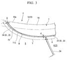
- the front pillar 2 of the vehicle body 1 is provided with a pillar outer panel 4 of an outside panel 3.
- the pillar outer panel 4 is provided with a rear-upper end portion 6 of a front fender panel 5, so that their exterior surfaces are level.
- a window-side garnish 7 which is made with resin and extends along the longitudinal direction thereof, is provided so as to adjacently extend along both of the pillar outer panel 4 and the front fender panel 5, at the inside of the vehicle width direction.
- the window-side garnish 7 is an ornamental member provided on an exterior surface of the vehicle body.
- a parting line 8 is provided along the gap between the window-side garnish 7 and the pillar outer panel 4/front fender panel 5.
- the parting line 8 maintains the gap between those adjacent members.
- the displacement of the window-side garnish 7 at a rear-end part 25 is restricted.
- the heat expansions and contractions of the window-side garnish 7 is absorbed at the side of a front-end part 14.
- Symbol B shows a bonnet.
- the window-side garnish 7 is provided with an ornamental part 9 having an outer surface which is level with the outer surfaces of the adjacent pillar outer panel 4 and the front fender panel 5.
- the ornamental part 9 is provided with an inside-fringe part 10 and an outside-fringe part 11, at the center part of the width direction, each extending in an slanted direction toward either inward or outward.
- four brackets 12 extending downward direction are provided along the longitudinal direction of the window-side garnish 7, with predetermined intervals.
- the brackets 12 are secured on an inside surface 13 of the pillar outer panel 4.
- a backside of the front-end part 14 of the ornamental part 9 is provided with a connection part 15.
- An upper fastening part 38 of a clip 16 is held at the connection part 15 in a slidable manner along the longitudinal direction of the window-side garnish 7 (the direction orthogonal to the figure sheet).
- the lower fastening part 17 of the clip 16 is held and fixed at an internal rack part 18 of the front fender panel 5.
- the clip 16 is fixed at the internal rack part 18 of the front fender panel 5, while the upper fastening part 38 of the clip 16 is slidable in relation to the connection part 15 at the backside of the front-end part 14 of the ornamental part 9. Therefore, the displacement of the window-side garnish 7 caused by heat expansion/contraction can be smoothly performed at the front-end part.
- the ornamental part 9 is provided with a leg part 20 at the inside of the vehicle width direction.
- the leg part 20 extends toward the front windshield 19, and arranged so that the longitudinal direction of the leg part 20 runs along the longitudinal direction of the window-side garnish 7.
- a seal member 22 fits into the leg part 20.
- a seal lip 21 of the seal member 22 tightly engages with the front windshield 19.
- the extending height of the leg part 20 becomes progressively shorter as it goes closer to the rear end of the window-side garnish 7.
- a drip part 23 is positioned at a side of the front windshield 19.
- the drip part 23 has a C-shaped cross-section and is constituted with the inside-fringe part 10 of the ornamental part 9 of the window-side garnish 7, the leg part 20, and the front windshield 19.
- the front-end part 14 of the ornamental part 9 of the window-side garnish 7 has a tapered shape in which an edge part 11a of the outside-fringe part 11 becomes gradually closer to an edge part 10a of the inside-fringe part 10, as it goes closer to the tip.
- the front-end part 14 is provided adjacent to a parting line 24 between the pillar outer panel 4 and the front fender panel 5.
- a rear-end part 25 of the window-side garnish 7 also has a tapered shape in which the edge part 11a of the outside-fringe part 11 becomes closer to the edge part 10a of the inside-fringe part 10, as it goes closer to the tip.
- the front-end part 14 of the window-side garnish 7 is provided with a front arc part 26, on the edge part 11a of the outside-fringe part 11.
- the rear-end part 25 is provided with a rear arc part 27, also on the edge part 11a of the outside-fringe part 11.
- a rear elastic lip 28 is adhered, on a part of the back surface ranging from the rear arc part 27 to a part of the edge part 10a on the side of the inside-fringe part 10 which is further front than the rear arc part 27.
- the rear elastic lip 28 has a shape which approximately fits the rear-end part 25 of the ornamental part 9.
- the rear elastic lip 28 is provided with a rear arc lip 30 which extends outward from the rear arc part 27 by a shape corresponding to a rear gap 29 (shown in FIG. 1 ) which opens between the rear arc part 27 of the ornamental part 9 and the pillar outer panel 4.
- the rear arc lip 30 fits the rear gap 29 to fill the rear gap 29.
- a tip of the rear arc lip 30 tightly engages with the pillar outer panel 4.
- a seal lip 31 is provided at an inner edge of the rear elastic lip 28.
- the seal lip 31 is tightly attached to the front windshield 19.
- the rear elastic lip 28 is formed by a mold-casting.
- a side elastic lip 33 is adhered at a side part of the window-side garnish 7, on the back surface of the outside-fringe part 11 of the ornamental part 9.
- the side elastic lip 33 is connected to the rear elastic lip 28 and extends to a position of the front-end part 14 of the window-side garnish 7.
- the side elastic lip 33 has a shape which approximately fits the edge part 11a of the outside-fringe part 11 of the ornamental part 9, the side elastic lip 33 is provided with a side part lip 34.
- the side part lip 34 extends outward from the edge part 11a of the outside-fringe part 11 of the ornamental part 9 by a shape corresponding to a side gap 32 (as shown in FIGS.
- the side part lip 34 fits the side gap 32 to fill the side gap 32.
- a tip of the side part lip 34 tightly engages with the pillar outer panel 4 and the front fender panel 5.
- the side elastic lip 33 is formed by an extrusion molding.
- a front elastic lip 35 is adhered at the front-end part 14 of the ornamental part 9, on the back surface of the outside-fringe part 11.
- the front elastic lip 35 is provided at a position extending from the front arc part 26 to the edge part 10a of the inside-fringe part 10.
- the front elastic lip 35 is provided continuously with the side elastic lip 33 so as to engage with the side elastic lip 33.
- the junction R at which the side elastic lip 33 and the front elastic lip 35 engages is provided at a position different from the parting line 24 between the pillar outer panel 4 and the rear-upper end portion 6 of the front fender panel 5. The junction R is shifted further front than the parting line 24.
- the front elastic lip 35 has a shape which approximately fits the front arc part 26 of the front-end part 14 of the ornamental part 9.
- the front elastic lip 35 is provided with a front arc lip 37 which extends outward from the front arc part 26 by a shape corresponding to a front gap 36 which opens between the front arc part 26 of the ornamental part 9 and the front fender panel 5.
- the front arc lip 37 fits the front gap 36 to fill the front gap 36.
- a tip of the front arc lip 37 tightly engages with the front fender panel 5 (as shown in FIGS. 6 and 8 ).
- the parting line 8 consists of the rear gap 29, the side gap 32, and the front gap 36.
- the front elastic lip 35 is formed by a mold-casting.
- the parting line 8 has an approximately constant width d at the entire rear gap 29 and in the range X of the side gap 32 starting from the rear gap 29 and reaching to the parting line 24 between the front fender panel 5 and the pillar outer panel 4.
- this is not the case at the other parts of the side gap 32, namely, in the range Y, which includes the front gap 36 and the part further to the front than the parting line 24 of the front fender panel 5 and the pillar outer panel 4.
- the width of the parting line 8 becomes gradually wider.
- the parting line 8 has the same width d as in the range X at the position of the parting line 24 between the front fender panel 5 and the pillar outer panel 4.
- the width of the parting line 8 becomes gradually wider until it finally reaches the width D (d ⁇ D).
- the parting line 8 extrudes sidewise by the width D.
- the width gradually increases as the parting line 8 extends bending inward along the front arc part 26.
- the parting line 8 extrudes to the front direction by the width D.
- the extruding width of the side part lip 34 of the side elastic lip 33 provided in the range Y is adjusted by shifting the installation position of the side elastic lip 33 relative to the ornamental part 9.
- the extruding width of the front arc lip 37 of the front elastic lip 35 is adjusted by the mold casting of the part, so that the extrusion width becomes gradually wider from the width d finally to the width D.
- a hinge cover 40 is provided on the internal rack part 18 of the front fender panel 5 so as to cover the junction of the window-side garnish 7 and the front fender panel 5, and cover the hinge which supports the bonnet B.
- the reference symbol 41 in FIG. 5 shows a cowling-top garnish provided at the underside edge of the front windshield 19.
- the window-side garnish 7 is made with resin and is tend to be affected by heat, resulting in substantial expansions and contractions of the window-side garnish 7 along the longitudinal direction thereof, and dislocations at the front-end part 14.
- the range Y of front-end part 14 includes the front gap 36 and the part of the side gap 32 further to the front than the parting line 24 of the front fender panel 5 and the pillar outer panel 4.
- the width of the parting line 8 becomes gradually wider as it goes closer to the front part thereof, until it finally reaches the width D (d ⁇ D).
- the front arc part 26 is provided at the front-end part 14 of the window-side garnish 7.
- the parting line 8 gradually bends inward as it gets closer to the tip part thereof. Accordingly, a larger margin for the expansion of the window-side garnish 7 along the longitudinal direction thereof is prepared at the front part of the window-side garnish 7. Therefore, a sufficient margin for the expansion can be secured at the front-end part 14 of the window-side garnish 7.
- the range X portion of the parting line 8 resides along the longitudinal direction of the window-side garnish 7. Since the width of the window-side garnish 7 is smaller than the length thereof, the displacement due to the heat is smaller in the range X. Therefore, in the range X, a smaller expansion-contraction margin is necessary, and the width of the protruding part can be maintained constant throughout the range X at the width d.
- the width d of the protruding part can be configured as small as possible, in order to realize a constitution which can deal with effects of heat, while having a fine appearance.
- the side part lip 34 of the side elastic lip 33 and the front arc lip 37 of the front elastic lip 35 are each designed to fit the varying width of the parting line 8 between the window-side garnish 7 and the adjacent pillar outer panel 4/front fender panel 5. Accordingly, the parting line 8 can be securely sealed.
- the dislocation caused by the effect of heat is larger.
- the extruding length d of the side part lip 34 of the side elastic lip 33 changes to the extruding length D of the front arc lip 37 of the front elastic lip 35 within the range Y.
- the lip width is widened so as to fit the width of the parting line 8. Therefore, as the dislocation of the side gap 32 and the front gap 36 caused by heat becomes larger, the lips can bend further, so that the engaging part between the window-side garnish 7 and the pillar outer panel 4 / front fender panel 5 can be maintained in an appropriate status.
- the front elastic lip 35 is formed by a mold-casting, the extrusion length of the front elastic lip 35 can be adjusted with a precise accuracy into a desired shape, so as to fit with the shape of the parting line 8 as the width changes in the part of the side gap 32 and in the front gap 36.
- the side elastic lip 33 is formed at a low cost by an extrusion molding.
- junction R of the side elastic lip 33 and the front elastic lip 35 is located at a different position (further to the front) from the position of the parting line 24 between the pillar outer panel 4 and the rear-upper end portion 6 of the front fender panel 5. Accordingly, the connection at the junction R of the side elastic lip 33 and the front elastic lip 35 is not positioned at the same position with the parting line 24 between the pillar outer panel 4 and the rear-upper end portion 6 of the front fender panel 5. Therefore, those junctions, i.e., the junction R and the parting line 24 do not appear conspicuous. In addition, the assemble status of the structure can be made steady.
- a resin garnish installation structure installed to a vehicle body exterior surface, having a resin garnish which extends along a longitudinal direction thereof, the resin garnish including: an exterior surface which is level with the vehicle body exterior surface; a first edge which extends along the longitudinal direction; a second edge which is provided on an opposite side of the first edge and extends along the longitudinal direction; and an end part provided at a tip in the longitudinal direction, wherein in a vicinity of the end part, the second edge gradually curbs toward the first edge, and the second edge joins the first edge at the end part, and the resin garnish is installed so that a gap is formed between the end part and the vehicle body exterior surface, the gap becoming wider as it gets closer to the tip of the resin garnish.
Landscapes
- Engineering & Computer Science (AREA)
- Mechanical Engineering (AREA)
- Vehicle Interior And Exterior Ornaments, Soundproofing, And Insulation (AREA)
Applications Claiming Priority (1)
| Application Number | Priority Date | Filing Date | Title |
|---|---|---|---|
| JP2008049845A JP4500858B2 (ja) | 2008-02-29 | 2008-02-29 | 樹脂製ガーニッシュの取付構造 |
Publications (2)
| Publication Number | Publication Date |
|---|---|
| EP2096000A1 true EP2096000A1 (de) | 2009-09-02 |
| EP2096000B1 EP2096000B1 (de) | 2010-02-17 |
Family
ID=40568723
Family Applications (1)
| Application Number | Title | Priority Date | Filing Date |
|---|---|---|---|
| EP09002661A Expired - Fee Related EP2096000B1 (de) | 2008-02-29 | 2009-02-25 | Installationsstruktur für Harzverzierungen |
Country Status (5)
| Country | Link |
|---|---|
| US (1) | US7954885B2 (de) |
| EP (1) | EP2096000B1 (de) |
| JP (1) | JP4500858B2 (de) |
| CN (1) | CN101519056B (de) |
| DE (1) | DE602009000003D1 (de) |
Cited By (1)
| Publication number | Priority date | Publication date | Assignee | Title |
|---|---|---|---|---|
| CN102039855A (zh) * | 2009-10-19 | 2011-05-04 | 本田技研工业株式会社 | 安装柱装饰件和叶子板面板的车身构造 |
Families Citing this family (9)
| Publication number | Priority date | Publication date | Assignee | Title |
|---|---|---|---|---|
| US8398157B2 (en) | 2010-08-26 | 2013-03-19 | Honda Motor Co., Ltd. | Pillar reduction by outer panel cut |
| CN102864477B (zh) * | 2011-07-08 | 2015-08-26 | 宁波市胜源技术转移有限公司 | 一种汽车装饰条及其外表处理方法 |
| CN103358865B (zh) * | 2013-07-30 | 2016-01-20 | 奇瑞汽车股份有限公司 | 密封件 |
| CN104802728B (zh) * | 2014-01-23 | 2019-02-22 | 标致雪铁龙(中国)汽车贸易有限公司 | 一种用于车辆的前风挡饰条的固定机构 |
| JP6146359B2 (ja) * | 2014-03-28 | 2017-06-14 | マツダ株式会社 | 車両のモール部材配設構造 |
| DE102015004413A1 (de) * | 2015-04-02 | 2016-10-06 | GM Global Technology Operations LLC (n. d. Ges. d. Staates Delaware) | Fahrzeugkarosserie |
| JP6579429B2 (ja) * | 2015-07-21 | 2019-09-25 | スズキ株式会社 | 内装部材の合わせ部構造 |
| CN108528355B (zh) * | 2017-03-01 | 2022-08-09 | 标致雪铁龙集团 | 连接汽车后部定窗与装饰面板的安装结构及汽车 |
| US12589702B2 (en) * | 2024-02-01 | 2026-03-31 | Honda Motor Co., Ltd. | Vehicle including a-pillar garnish extending into airflow gap and underneath hood |
Citations (7)
| Publication number | Priority date | Publication date | Assignee | Title |
|---|---|---|---|---|
| JPS628844A (ja) * | 1985-07-05 | 1987-01-16 | Nissan Motor Co Ltd | 車両用ピラ−カバ−取付構造 |
| JPS6268120A (ja) * | 1985-09-20 | 1987-03-28 | Nissan Motor Co Ltd | 自動車におけるフロントウインドウガラスモ−ルとフロントフエンダとの合わせ部構造 |
| WO2005030513A1 (de) * | 2003-09-24 | 2005-04-07 | Daimlerchrysler Ag | Blendelement |
| JP2005119457A (ja) | 2003-10-16 | 2005-05-12 | Honda Motor Co Ltd | カウルトップガーニッシュ構造 |
| EP1798113A2 (de) * | 2005-12-16 | 2007-06-20 | Newfrey LLC | Clipbefestigungsanordnung für ein Fahrzeugverkleidungsteil |
| US20070164585A1 (en) * | 2005-11-28 | 2007-07-19 | Minoru Hasegawa | Vehicle pillar garnish mounting structure |
| JP2008049845A (ja) | 2006-08-24 | 2008-03-06 | Mazda Motor Corp | 自動車用シート装置 |
Family Cites Families (5)
| Publication number | Priority date | Publication date | Assignee | Title |
|---|---|---|---|---|
| GB2318551B (en) * | 1996-10-25 | 2001-04-18 | Nissan Motor | Interior material for automotive vehicle |
| JP3299230B2 (ja) * | 1999-09-03 | 2002-07-08 | 本田技研工業株式会社 | ピラーガーニッシュの取り付け構造 |
| JP3529739B2 (ja) * | 2001-03-26 | 2004-05-24 | 東海興業株式会社 | ピラーガーニッシュ |
| JP3974097B2 (ja) * | 2003-10-16 | 2007-09-12 | 本田技研工業株式会社 | カウルトップガーニッシュ構造 |
| JP4413731B2 (ja) * | 2004-09-28 | 2010-02-10 | 本田技研工業株式会社 | サイドシルガーニッシュ |
-
2008
- 2008-02-29 JP JP2008049845A patent/JP4500858B2/ja not_active Expired - Fee Related
-
2009
- 2009-02-24 US US12/391,676 patent/US7954885B2/en not_active Expired - Fee Related
- 2009-02-25 EP EP09002661A patent/EP2096000B1/de not_active Expired - Fee Related
- 2009-02-25 DE DE602009000003T patent/DE602009000003D1/de active Active
- 2009-02-27 CN CN200910126114XA patent/CN101519056B/zh not_active Expired - Fee Related
Patent Citations (7)
| Publication number | Priority date | Publication date | Assignee | Title |
|---|---|---|---|---|
| JPS628844A (ja) * | 1985-07-05 | 1987-01-16 | Nissan Motor Co Ltd | 車両用ピラ−カバ−取付構造 |
| JPS6268120A (ja) * | 1985-09-20 | 1987-03-28 | Nissan Motor Co Ltd | 自動車におけるフロントウインドウガラスモ−ルとフロントフエンダとの合わせ部構造 |
| WO2005030513A1 (de) * | 2003-09-24 | 2005-04-07 | Daimlerchrysler Ag | Blendelement |
| JP2005119457A (ja) | 2003-10-16 | 2005-05-12 | Honda Motor Co Ltd | カウルトップガーニッシュ構造 |
| US20070164585A1 (en) * | 2005-11-28 | 2007-07-19 | Minoru Hasegawa | Vehicle pillar garnish mounting structure |
| EP1798113A2 (de) * | 2005-12-16 | 2007-06-20 | Newfrey LLC | Clipbefestigungsanordnung für ein Fahrzeugverkleidungsteil |
| JP2008049845A (ja) | 2006-08-24 | 2008-03-06 | Mazda Motor Corp | 自動車用シート装置 |
Cited By (3)
| Publication number | Priority date | Publication date | Assignee | Title |
|---|---|---|---|---|
| CN102039855A (zh) * | 2009-10-19 | 2011-05-04 | 本田技研工业株式会社 | 安装柱装饰件和叶子板面板的车身构造 |
| EP2311690A3 (de) * | 2009-10-19 | 2012-10-10 | Honda Motor Co., Ltd. | Fahrzeugaufbau zum Anpassen einer Säulenverkleidung und eines Kotflügels |
| CN102039855B (zh) * | 2009-10-19 | 2013-06-19 | 本田技研工业株式会社 | 安装柱装饰件和叶子板面板的车身构造 |
Also Published As
| Publication number | Publication date |
|---|---|
| DE602009000003D1 (de) | 2010-04-01 |
| US20090218850A1 (en) | 2009-09-03 |
| JP4500858B2 (ja) | 2010-07-14 |
| JP2009202838A (ja) | 2009-09-10 |
| CN101519056B (zh) | 2011-03-02 |
| US7954885B2 (en) | 2011-06-07 |
| CN101519056A (zh) | 2009-09-02 |
| EP2096000B1 (de) | 2010-02-17 |
Similar Documents
| Publication | Publication Date | Title |
|---|---|---|
| EP2096000B1 (de) | Installationsstruktur für Harzverzierungen | |
| CN1958345B (zh) | 保险杠固定用具及保险杠的安装结构 | |
| US8157303B2 (en) | Vehicle end structure | |
| US9561756B2 (en) | Trim member attachment structure | |
| JP5492167B2 (ja) | 車両用バンパ構造 | |
| US8641135B2 (en) | Sill panel | |
| US7988224B2 (en) | Cowl cover assembly for a motor vehicle | |
| US20170137065A1 (en) | Motor vehicle body | |
| US8827358B2 (en) | Lining for a vehicle bonnet | |
| US20220410982A1 (en) | Vehicle side structure | |
| JP4753983B2 (ja) | サイドスプラッシュガードの取付構造 | |
| JP6238129B2 (ja) | インストルメントパネル側部及びフロントピラートリム下部の合わせ部構造 | |
| JP5961502B2 (ja) | バンパ取付け用リテーナ | |
| JP4990986B2 (ja) | テールライト構造 | |
| JP3974097B2 (ja) | カウルトップガーニッシュ構造 | |
| JP4257170B2 (ja) | サイドスプラッシュガードの取付構造 | |
| US20250249843A1 (en) | Resin rail garnish | |
| JP6241106B2 (ja) | 車両用ドア構造 | |
| JP2007083943A (ja) | ガラスランの組付構造 | |
| JP6210833B2 (ja) | 車両用カバー装置 | |
| JP2007223488A (ja) | フェンダーパネル構造 | |
| JP6798300B2 (ja) | 車両用フロントバンパ | |
| JP4591209B2 (ja) | シール部材の取付構造 | |
| JP2005119487A (ja) | 自動車用ベルトラインモール断面構造 | |
| JP6500641B2 (ja) | 車両用ドアトリム |
Legal Events
| Date | Code | Title | Description |
|---|---|---|---|
| PUAI | Public reference made under article 153(3) epc to a published international application that has entered the european phase |
Free format text: ORIGINAL CODE: 0009012 |
|
| 17P | Request for examination filed |
Effective date: 20090225 |
|
| AK | Designated contracting states |
Kind code of ref document: A1 Designated state(s): AT BE BG CH CY CZ DE DK EE ES FI FR GB GR HR HU IE IS IT LI LT LU LV MC MK MT NL NO PL PT RO SE SI SK TR |
|
| AX | Request for extension of the european patent |
Extension state: AL BA RS |
|
| GRAP | Despatch of communication of intention to grant a patent |
Free format text: ORIGINAL CODE: EPIDOSNIGR1 |
|
| GRAS | Grant fee paid |
Free format text: ORIGINAL CODE: EPIDOSNIGR3 |
|
| GRAA | (expected) grant |
Free format text: ORIGINAL CODE: 0009210 |
|
| AK | Designated contracting states |
Kind code of ref document: B1 Designated state(s): DE GB |
|
| REG | Reference to a national code |
Ref country code: GB Ref legal event code: FG4D |
|
| REF | Corresponds to: |
Ref document number: 602009000003 Country of ref document: DE Date of ref document: 20100401 Kind code of ref document: P |
|
| AKX | Designation fees paid |
Designated state(s): DE GB |
|
| PLBE | No opposition filed within time limit |
Free format text: ORIGINAL CODE: 0009261 |
|
| STAA | Information on the status of an ep patent application or granted ep patent |
Free format text: STATUS: NO OPPOSITION FILED WITHIN TIME LIMIT |
|
| 26N | No opposition filed |
Effective date: 20101118 |
|
| REG | Reference to a national code |
Ref country code: DE Ref legal event code: R084 Ref document number: 602009000003 Country of ref document: DE |
|
| REG | Reference to a national code |
Ref country code: GB Ref legal event code: 746 Effective date: 20141114 |
|
| REG | Reference to a national code |
Ref country code: DE Ref legal event code: R084 Ref document number: 602009000003 Country of ref document: DE Effective date: 20141120 |
|
| PGFP | Annual fee paid to national office [announced via postgrant information from national office to epo] |
Ref country code: DE Payment date: 20150218 Year of fee payment: 7 |
|
| PGFP | Annual fee paid to national office [announced via postgrant information from national office to epo] |
Ref country code: GB Payment date: 20150225 Year of fee payment: 7 |
|
| REG | Reference to a national code |
Ref country code: DE Ref legal event code: R119 Ref document number: 602009000003 Country of ref document: DE |
|
| GBPC | Gb: european patent ceased through non-payment of renewal fee |
Effective date: 20160225 |
|
| PG25 | Lapsed in a contracting state [announced via postgrant information from national office to epo] |
Ref country code: DE Free format text: LAPSE BECAUSE OF NON-PAYMENT OF DUE FEES Effective date: 20160901 Ref country code: GB Free format text: LAPSE BECAUSE OF NON-PAYMENT OF DUE FEES Effective date: 20160225 |