EP2096052B1 - Verfahren und System zur Steuerung von Produktströmen - Google Patents
Verfahren und System zur Steuerung von Produktströmen Download PDFInfo
- Publication number
- EP2096052B1 EP2096052B1 EP08425115A EP08425115A EP2096052B1 EP 2096052 B1 EP2096052 B1 EP 2096052B1 EP 08425115 A EP08425115 A EP 08425115A EP 08425115 A EP08425115 A EP 08425115A EP 2096052 B1 EP2096052 B1 EP 2096052B1
- Authority
- EP
- European Patent Office
- Prior art keywords
- products
- flow
- flows
- derived
- stations
- Prior art date
- Legal status (The legal status is an assumption and is not a legal conclusion. Google has not performed a legal analysis and makes no representation as to the accuracy of the status listed.)
- Not-in-force
Links
- 238000000034 method Methods 0.000 title claims description 11
- 238000000605 extraction Methods 0.000 claims abstract description 41
- 238000007689 inspection Methods 0.000 claims abstract description 23
- 238000003491 array Methods 0.000 claims abstract description 8
- 230000001105 regulatory effect Effects 0.000 claims abstract description 8
- 230000015572 biosynthetic process Effects 0.000 claims description 9
- 238000005755 formation reaction Methods 0.000 claims description 9
- 238000011179 visual inspection Methods 0.000 claims 4
- 238000005286 illumination Methods 0.000 claims 2
- 238000009825 accumulation Methods 0.000 abstract description 12
- 230000035508 accumulation Effects 0.000 abstract description 12
- 238000004806 packaging method and process Methods 0.000 abstract description 11
- 230000000007 visual effect Effects 0.000 abstract description 2
- 230000000694 effects Effects 0.000 description 3
- 230000003287 optical effect Effects 0.000 description 3
- 230000001276 controlling effect Effects 0.000 description 2
- 230000009977 dual effect Effects 0.000 description 2
- 239000000463 material Substances 0.000 description 2
- 238000005259 measurement Methods 0.000 description 2
- 230000006978 adaptation Effects 0.000 description 1
- 238000004458 analytical method Methods 0.000 description 1
- 235000015895 biscuits Nutrition 0.000 description 1
- 238000006243 chemical reaction Methods 0.000 description 1
- 238000010276 construction Methods 0.000 description 1
- 230000003247 decreasing effect Effects 0.000 description 1
- 230000002950 deficient Effects 0.000 description 1
- 230000001934 delay Effects 0.000 description 1
- 238000001514 detection method Methods 0.000 description 1
- 238000004519 manufacturing process Methods 0.000 description 1
- 238000009877 rendering Methods 0.000 description 1
- 238000010079 rubber tapping Methods 0.000 description 1
Images
Classifications
-
- B—PERFORMING OPERATIONS; TRANSPORTING
- B65—CONVEYING; PACKING; STORING; HANDLING THIN OR FILAMENTARY MATERIAL
- B65G—TRANSPORT OR STORAGE DEVICES, e.g. CONVEYORS FOR LOADING OR TIPPING, SHOP CONVEYOR SYSTEMS OR PNEUMATIC TUBE CONVEYORS
- B65G43/00—Control devices, e.g. for safety, warning or fault-correcting
- B65G43/08—Control devices operated by article or material being fed, conveyed or discharged
Definitions
- the present invention relates to techniques for controlling product flows.
- the invention has been developed with particular attention paid to the possible use in plants for automatic packaging of products, such as, for example, foodstuff products.
- Control of the advance of the products comprised in the "derived" flows usually presupposes formation of quite a long accumulation of products, and some products, such as certain foodstuff products, by their very nature and/or shape do not allow such accumulation, thus rendering the solution impracticable.
- the systems for control of the accumulation are located at a distance from the area in which the derived flows are "tapped" from the original flow.
- the amount of products that are travelling between the area for formation of the derived flows and the control systems is not quantified and hence may vary in contrast with the action that is sought by the accumulation.
- the object of the present invention is hence to overcome the aforesaid drawbacks.
- the above object is achieved thanks to a method having the characteristics recalled in the ensuing claims.
- the invention moreover relates to a corresponding system as set out in claim 4.
- the proposed solution envisages positioning, as close as possible to the point for formation of the derived flows, an inspection station that sees to detecting and counting the products travelling in unit time.
- the counting datum By causing the counting datum to interact with a function of control of the action of extracting products from the original flow, it is possible to regulate the amount of products sent into the various derived flows, obtaining for example a precise balancing thereof and/or a practically real-time adaptation to possible variations required in the derived flows (for example, because a processing/treatment station supplied with one of such flows is momentarily in conditions of arrest).
- the aforesaid units are then able to respond in a practically immediate way to the request for a larger or smaller number of products by the control system.
- Embodiments of the counting system described herein can find application in other situations, in particular where there is required the balancing of arrival of products between two or more sections of a packaging machine.
- the system can prove very advantageous because, as the amount of products varies in unit time, it acts in a fast way, reducing to a few units (and virtually eliminating) the difference between the flows.
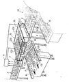
- the reference number 10 designates as a whole a system for forming, starting from an original flow F of products P (for example, foodstuff products such as biscuits laid “flat") a plurality of derived flows F1, F2, ... that are to be fed towards respective processing stations, such as, once again by way of example, packaging machines (flow-pack machines, boxing machines, etc.) not specifically illustrated.
- an original flow F of products P for example, foodstuff products such as biscuits laid “flat
- respective processing stations such as, once again by way of example, packaging machines (flow-pack machines, boxing machines, etc.) not specifically illustrated.
- the original flow F of products P which may - be imagined as coming, once again by way of example, from a source such as a baking oven, has the character of a generically "disorderly" (or “non-orderly") array, i.e., of an array in which orderly formations, such as rows or ranks of products in some way aligned to one another, are not recognizable: it is, in other words, a flow of products P set in a substantially random way.
- the system 10 comprises a plurality of extraction stations 12 set cascaded along the path of flow F of products P.
- the extraction stations 12 are hence designed to be traversed by the flow F of products P and derive from the flow F of products P that traverses the respective derived flows F1, F2, ... of products.
- the annexed figure illustrates in detail just one of the extraction stations 12, which, in the example of embodiment illustrated herein, is in actual fact a station with a "dual" or “combined” structure in so far as it comprises two sections for generating at output, on a conveyor 126, two flows F1 and F2 of products P.
- such a combined structure may be in effect considered as constituted by a pair of extraction stations that are able to derive, from the flow F of products P that traverses them, two combined derived flows F1, F2 of products P.
- the profile of another extraction station 12 (which can have either a single structure or a combined structure like the one just described) is indicated by a dashed line.
- This representation is aimed at highlighting the fact that the extraction stations 12 (possibly with combined or dual structure, for the generation of two flows sent on the same output conveyor, but with different capacities) can be freely set cascaded along the path of the products of the main flow F of products P in any number according to the needs.
- a generic extraction station 12 is activated selectively for "tapping" from the main flow F at least one respective derived flow Fj, which is to be fed to a respective treatment station (or a respective section of a treatment station) situated downstream.
- each station 12 can comprise one or more (for example, two, in the example illustrated) paddle systems 120 comprising paddles connected according to a general track structure.
- Each of said structures is set above the conveyor (for example, a belt conveyor) 14 on which there arrives - moving from left to right, in the example represented - the flow F of incoming products P.
- the conveyor for example, a belt conveyor
- the track structure is set spanning, and crosswise with respect to, the conveyor 14, whilst the paddles 120 are aligned in the direction of advance of the products P on the conveyor 14. It follows that the paddles 120 mounted on the bottom branch of the track structure, albeit extending with their distal edge in the strict vicinity of the plane of the conveyor 14, on which the products P advance, do not hinder in themselves (but for a possible marginal action of deviation) the movement of traversal of the station 12 by the products P.
- the various track structures are motor-powered (via respective motor drives 122), they make it possible to impart on to the paddles 120 mounted on the bottom branch of each track structure a lateral movement that brings said paddles to "sweep" the plane of the conveyor 14 on which the products P advance and to deflect the products P themselves laterally, getting them to come out laterally from the conveyor (for example, sending them on an inclined plate 16, functioning as chute or drop tray) so as to form the various derived flows F1, F2, ....
- the speeds of operation of the various motor drives 122 it is hence possible to adjust the speed at which the paddles 120 of the various stations 12 sweep laterally the plane of the conveyor 14, so as to regulate (taking of course into account the speed of advance of the "original" flow F of the products P on the conveyor 14) the intensities of the respective derived flows F1, F2, ....
- the extraction stations 12 hence have adjustable speeds of operation for regulating the intensities of the respective derived flows F1, F2, ... (i.e., generically, Fj).
- the paddles 120 of the two combined sections of the extraction station 12 convey on the transverse belt 126 two combined flows F1 and F2, each comprising an amount of products (in terms of products per unit time) proportional to their speed and to the amount of products that they intercept on the incoming belt.
- the paddle systems 120 can be strictly set alongside one another or else set at a distance so as to be able to feed respective derived flows F1, F2, forming respective lines of feed of the products P to respective treatment or manipulation stations (for example, packaging machines) or else to respective sections of said stations.
- each derived flow Fj i.e., the amount of products P per unit time sent towards the processing station or stations located downstream
- rate of each derived flow Fj is a factor that may be influenced by many variables, also on account of the possible presence of systems of accumulation and control of the length of said accumulation. These systems can intervene for stopping or restarting the corresponding extraction station 12 in accordance with the length of the "queue" of products accumulated.
- the system described herein envisages that there be coupled to the extraction stations 12 inspection stations 130 capable of detecting the intensity (number of products P per unit time) of the corresponding derived flow Fj at output from the extraction station itself.
- one and the same inspection station 130 acts on the two flows F1, F2 at output from the two stations 12 combined with one another (which hence share the same inspection station 130) immediately downstream of the chute/drop tray 16, i.e., as soon as the products P arrive on the conveyor 126.
- a control unit K (such as, for example, a Programmable Logic Controller or PLC or else a PC for industrial use - this may of course be the same control unit already envisaged for controlling and regulating operation of the system 10 as a whole) receives the measurement signal (products per unit time) supplied by the inspection unit 130 associated to the various extraction stations 12 - hence to various flows F1, F2, ..., Fj - and controls the various motor drives 122 accordingly so as to regulate (in a way and according to criteria in themselves known) the speeds of operation of the extraction stations 12 as a function of the intensities of said derived flows detected by the inspection stations 130.
- the measurement signal products per unit time
- the solution described herein envisages positioning the action of detection of the intensities or rates (number of products P per unit time) of the derived flow Fj as close as possible to the extraction station 12, i.e., where the derived flow is formed, before any action of accumulation/ordering can take place.
- the aim of the above is to be able to interact with the function of control and regulation of the motor drives 122 by the unit K in order to regulate as desired, according to the need, the amount of products P that are sent in the various derived flows Fj.
- the stations 12 are thus able to respond practically immediately to the requirement of a greater or smaller number of products, by the control system, it being likewise possible to reduce (and in effect eliminate) the accumulations of products, in particular when delicate products are treated.
- the solution described herein makes it possible, as the amount of products per unit time varies, to act in a fast way reducing to a few units (and virtually eliminating) the difference between the flows.
- an inspection station 130 that can be used in the framework of the solution described herein for detecting the intensity of the two flows F1 and F2 is the inspection station available under the commercial name IVC-3D Industrial Vision Camera manufactured by the company Sick-IVP of Waldkirch - Germany.
- Said inspection station is able to scan each flow F1, F2 of products P subjected to measurement (namely, counting of the number of products per unit time) with a laser beam projected from above the products P in a vertical direction, i.e., in a direction orthogonal with respect to the conveyor.
- the inspection station hence comprises an optical sensor, which is able to detect from above, but sideways on, i.e., slantwise, the scanning trace "described" by the laser beam.
- This scanning trace will comprise in general plane stretches (corresponding to the areas in which the laser beam comes to scan the surface of the conveyor 126) separated by "humps” (corresponding to the areas in which the beam laser comes to scan the surface of the products that advance on the conveyor 126, constituting elements in relief with respect to the conveyor 126 itself).
- the unit is hence able to supply a counting datum corresponding to the number of products P per unit time advancing on the conveyor 126, even when said products are arranged in an altogether scattered and disorderly way.
- a laser station of the above type can divide its range of action into two or more sections, when, as in the case represented herein, a single extraction station 12 is able to generate two distinct flows F1, F2.
- Results as a whole similar to the ones described herein can be obtained also with other inspection stations known in the art, for example via a video camera (such as a CCD video camera for industrial use) equipped with processing cards, able to perform a function of visual identification of the individual products P, with corresponding counting function.
- a video camera such as a CCD video camera for industrial use
- processing cards able to perform a function of visual identification of the individual products P, with corresponding counting function.
Landscapes
- Control Of Conveyors (AREA)
- Sorting Of Articles (AREA)
- Attitude Control For Articles On Conveyors (AREA)
- Investigating Materials By The Use Of Optical Means Adapted For Particular Applications (AREA)
Claims (12)
- Verfahren zum Behandeln eines Stromes (F) von in einer ungeordneten Anordnung vorrückenden Erzeugnissen (P), wobei das Verfahren den Vorgang des entlang des Stromes (F) von Erzeugnissen (P) erfolgenden Kaskadierens einer Mehrzahl von von dem Strom (F) von Erzeugnissen (P) zu durchquerenden Entnahmestationen (12) beinhaltet, wobei die Entnahmestationen (12) aus dem Strom (F) von sie durchquerenden Erzeugnissen (P) jeweilige abgezweigte Ströme (F1, F2, ..., Fj) von Erzeugnissen (P) abzweigen und eine anpassbare Betriebsgeschwindigkeit (122) zum Regulieren der Intensitäten der jeweiligen abgezweigten Ströme (F1, F2, ... , Fj) aufweisen,
wobei das Verfahren durch die nachfolgenden Vorgänge gekennzeichnet ist:wenigstens vorübergehend für die abgezweigten Ströme (F1, F2, ... , Fj) am Ausgang aus den Entnahmestationen (12) erfolgendes Wahren des Charakters der ungeordneten Anordnungen von vorrückenden Erzeugnissen;bei der Prüfung der ungeordneten Anordnungen von in den abgezweigten Strömen vorrückenden Erzeugnissen erfolgendes Erfassen (130) der Intensitäten der am Ausgang aus den Entnahmestationen (12) abgezweigten Ströme (F1, F2, ..., Fj); undRegulieren (K, 122) der Betriebsgeschwindigkeiten der Entnahmestationen (12) als Funktion der Intensitäten der durch die Prüfung erfassten abgezweigten Ströme. - Verfahren nach Anspruch 1, beinhaltend den Vorgang des Erfassens der Intensitäten der am Ausgang der Entnahmestationen (12) abgezweigten Ströme (F1, F2, ... , Fj) mittels einer optischen Prüfung (130) der ungeordneten Anordnungen von in den abgezweigten Strömen (F1, F2, ... , Fj) vorrückenden Erzeugnissen.
- Verfahren nach Anspruch 2, wobei die optische Prüfung (130) die nachfolgenden Vorgänge beinhaltet:Anstrahlen der ungeordneten Anordnungen von vorrückenden Erzeugnissen (P) mit einem Lichtstrahl senkrecht zu der Anordnung;Erfassen der Anleuchtspur der Erzeugnisse (P) in der Anordnung entsprechend einer Richtung schräg in Bezug auf den zu der Anordnung senkrechten Lichtstrahl, wobei die Spur Unregelmäßigkeiten entsprechend den angestrahlten Erzeugnissen (P) darstellt;undAnalysieren der Spur durch Erfassen der Unregelmäßigkeiten und hieraus erfolgendes Ableiten der Anzahl von Erzeugnissen in dem Strom.
- System zum Behandeln eines Stromes (F) von in einer ungeordneten Anordnung vorrückenden Erzeugnissen (P), wobei das System eine Mehrzahl von Entnahmestationen (12) umfasst, die kaskadenartig entlang des Stromes (F) von Erzeugnissen (P) angeordnet sind; wobei die Entnahmestationen (12) von dem Strom (F) von Erzeugnissen (P) durchquerbar sind, um aus dem Strom (F) von sie durchquerenden Erzeugnissen (P) jeweilige abgezweigte Ströme (F1, F2, ..., Fj) von Erzeugnissen (P) mit einer anpassbaren Betriebsgeschwindigkeit zur Regelung der Intensitäten der jeweiligen abgezweigten Ströme (F1, F2, ..., Fj) abzuzweigen,
wobei das System dadurch gekennzeichnet ist, dass es umfasst:wenigstens eine Prüfungsstation (130), die mit den Entnahmestationen (12) gekoppelt ist, um die Intensitäten der abgezweigten Ströme (F1, F2, ..., Fj) am Ausgang aus den Entnahmestationen (12) zu erfassen, während die abgezweigten Ströme (F1, F2, ... ,Fj) wenigstens vorübergehend als ungeordnete Anordnungen von vorrückenden Erzeugnissen beibehalten werden; undeine Steuereinheit (K), die funktionell mit der wenigstens einen Prüfungsstation (130) und den Entnahmestationen (12) verbunden ist, um die Betriebsgeschwindigkeiten (122) der Entnahmestationen (12) als Funktion der Intensitäten der von der wenigstens einen Prüfungsstation (130) erfassten abgezweigten Ströme (F1, F2, ..., Fj) zu regulieren. - System nach Anspruch 4, beinhaltend wenigstens eine Entnahmestation (12), in der die Erzeugnisse (P) des Stromes (F) seitlich hin zu einer Rutsche oder Fallbahn (16) zur Bildung von wenigstens einem (F1, F2) der abgezweigten Ströme (F1, F2, ..., Fj) geschoben (120) werden, wobei die wenigstens eine Prüfungsstation (130) in einer Richtung entsprechend der Rutsche oder Fallbahn (16) wirkt.
- System nach Anspruch 4 oder Anspruch 5, beinhaltend ein Paar von kombinierten Entnahmestationen (12) zum aus dem Strom (F) von sie durchquerenden Erzeugnissen (P) erfolgenden Abzweigen von zwei kombinierten abgezweigten Strömen (F1, F2) von Erzeugnissen (P), wobei die wenigstens eine Prüfungsstation (130) an beiden der kombinierten abgezweigten Ströme (F1, F2) von Erzeugnissen (P) wirkt.
- System nach einem der Ansprüche 4 bis 6, beinhaltend ein Paar von kombinierten Entnahmestationen (12) zum aus dem Strom (F) von sie durchquerenden Erzeugnissen (P) erfolgenden Abzweigen von zwei kombinierten abgezweigten Strömen (F1, F2) von Erzeugnissen (P), wobei dem Paar von kombinierten Entnahmestationen (12) ein einziger Ausgabeförderer (126) zum Fördern der beiden kombinierten abgezweigten Ströme (F1, F2) von Erzeugnissen (P) zugeordnet ist.
- System nach einem der Ansprüche 4 bis 7, beinhaltend wenigstens eine Entnahmestation (12) mit Schaufelgebilden (120), die sich mit dem Strom (F) von Erzeugnissen (P) erstrecken, wobei die Schaufelgebilde (120) motorgetrieben (122) sind, um den Erzeugnissen (P), die die abgezweigten Ströme (F1, F2, ..., Fj) bilden sollen, eine Stoßbewegung seitlich in Bezug auf den Strom (F) von Erzeugnissen (P) zu verleihen.
- System nach Anspruch 8, wobei die Schaufelgebilde (120) in einer motorgetriebenen Schienenstruktur (122) montiert sind.
- System nach einem der Ansprüche 4 bis 9, wobei die wenigstens eine Prüfungsstation (130) eine optische Prüfungsstation (130) ist.
- System nach Anspruch 10, wobei die optische Prüfungsstation (130) beinhaltet:eine Lichtquelle zum Anstrahlen der ungeordneten Anordnungen von vorrückenden Erzeugnissen (P) mit einem Lichtstrahl senkrecht zu der Anordnung; undeinen Detektor zum Erfassen der Anleuchtspur der Erzeugnisse (P) in der Anordnung entsprechend einer Richtung schräg in Bezug auf den zu der Anordnung senkrechten Lichtstrahl, wobei die Spur Unregelmäßigkeiten entsprechend den angestrahlten Erzeugnissen (P) darstellt und damit die Anzahl von Erzeugnissen in dem Strom angibt.
- System nach Anspruch 11, wobei die Lichtquelle eine Laserquelle ist.
Priority Applications (8)
| Application Number | Priority Date | Filing Date | Title |
|---|---|---|---|
| ES08425115T ES2376953T3 (es) | 2008-02-26 | 2008-02-26 | Procedimiento y sistema para controlar flujos de productos |
| EP08425115A EP2096052B1 (de) | 2008-02-26 | 2008-02-26 | Verfahren und System zur Steuerung von Produktströmen |
| AT08425115T ATE537091T1 (de) | 2008-02-26 | 2008-02-26 | Verfahren und system zur steuerung von produktströmen |
| AU2008230058A AU2008230058A1 (en) | 2008-02-26 | 2008-10-23 | A method and system for controlling product flows |
| US12/257,526 US20090211877A1 (en) | 2008-02-26 | 2008-10-24 | Method and system for controlling product flows |
| MX2008013877A MX2008013877A (es) | 2008-02-26 | 2008-10-29 | Metodo y sistema para controlar flujos de producto. |
| CA002642398A CA2642398A1 (en) | 2008-02-26 | 2008-10-30 | A method and system for controlling product flows |
| BRPI0902934-6A BRPI0902934A2 (pt) | 2008-02-26 | 2009-01-26 | método e sistema para controlar fluxos de produtos |
Applications Claiming Priority (1)
| Application Number | Priority Date | Filing Date | Title |
|---|---|---|---|
| EP08425115A EP2096052B1 (de) | 2008-02-26 | 2008-02-26 | Verfahren und System zur Steuerung von Produktströmen |
Publications (2)
| Publication Number | Publication Date |
|---|---|
| EP2096052A1 EP2096052A1 (de) | 2009-09-02 |
| EP2096052B1 true EP2096052B1 (de) | 2011-12-14 |
Family
ID=39589258
Family Applications (1)
| Application Number | Title | Priority Date | Filing Date |
|---|---|---|---|
| EP08425115A Not-in-force EP2096052B1 (de) | 2008-02-26 | 2008-02-26 | Verfahren und System zur Steuerung von Produktströmen |
Country Status (8)
| Country | Link |
|---|---|
| US (1) | US20090211877A1 (de) |
| EP (1) | EP2096052B1 (de) |
| AT (1) | ATE537091T1 (de) |
| AU (1) | AU2008230058A1 (de) |
| BR (1) | BRPI0902934A2 (de) |
| CA (1) | CA2642398A1 (de) |
| ES (1) | ES2376953T3 (de) |
| MX (1) | MX2008013877A (de) |
Families Citing this family (5)
| Publication number | Priority date | Publication date | Assignee | Title |
|---|---|---|---|---|
| DE102009043976B4 (de) * | 2009-09-10 | 2021-07-29 | Krones Aktiengesellschaft | Fördereinrichtung und Verfahren zu deren Steuerung |
| DE102011080122B4 (de) * | 2011-07-29 | 2017-07-13 | Steffen Hahn | Verfahren und Vorrichtung zum Aufteilen eines Produktstroms |
| CN108438289B (zh) * | 2018-05-14 | 2023-08-18 | 温州海航机械有限公司 | 全自动多列四边封包装机的分料装置 |
| CN110786124A (zh) * | 2019-11-30 | 2020-02-14 | 徐州库卡机械科技有限公司 | 一种根菜联合收获机的对向输送装置 |
| CN116714975B (zh) * | 2023-08-10 | 2023-10-31 | 河北卓然睿和自动化科技有限公司 | 料片自动定位调整方法、装置、加工机及存储介质 |
Family Cites Families (7)
| Publication number | Priority date | Publication date | Assignee | Title |
|---|---|---|---|---|
| US2758728A (en) * | 1952-12-20 | 1956-08-14 | Woodman Company Inc | Automatic hopper feed conveyor mechanism |
| US2966253A (en) * | 1955-09-19 | 1960-12-27 | William A Gerrans | Variable speed drive control for material handling |
| US3917050A (en) * | 1974-02-28 | 1975-11-04 | Vaughn Gregor | Distributor with discharge conveyors |
| US4540082A (en) * | 1983-05-17 | 1985-09-10 | Kmg Systems Limited | Vibratory distribution system |
| US4986410A (en) * | 1988-03-01 | 1991-01-22 | Shields Winston E | Machine control apparatus using wire capacitance sensor |
| IT1240709B (it) | 1990-08-17 | 1993-12-17 | Cavanna Spa | Procedimento per regolare l'avanzamento di articoli in un sistema di convogliamento, particolarmente un sistema automatico di confezionamento, e relativo sistema. |
| US6610954B2 (en) * | 2001-02-26 | 2003-08-26 | At&C Co., Ltd. | System for sorting commercial articles and method therefor |
-
2008
- 2008-02-26 ES ES08425115T patent/ES2376953T3/es active Active
- 2008-02-26 EP EP08425115A patent/EP2096052B1/de not_active Not-in-force
- 2008-02-26 AT AT08425115T patent/ATE537091T1/de active
- 2008-10-23 AU AU2008230058A patent/AU2008230058A1/en not_active Abandoned
- 2008-10-24 US US12/257,526 patent/US20090211877A1/en not_active Abandoned
- 2008-10-29 MX MX2008013877A patent/MX2008013877A/es active IP Right Grant
- 2008-10-30 CA CA002642398A patent/CA2642398A1/en not_active Abandoned
-
2009
- 2009-01-26 BR BRPI0902934-6A patent/BRPI0902934A2/pt not_active IP Right Cessation
Also Published As
| Publication number | Publication date |
|---|---|
| MX2008013877A (es) | 2009-08-28 |
| BRPI0902934A2 (pt) | 2010-06-22 |
| US20090211877A1 (en) | 2009-08-27 |
| AU2008230058A1 (en) | 2009-09-10 |
| ATE537091T1 (de) | 2011-12-15 |
| EP2096052A1 (de) | 2009-09-02 |
| CA2642398A1 (en) | 2009-08-26 |
| ES2376953T3 (es) | 2012-03-21 |
Similar Documents
| Publication | Publication Date | Title |
|---|---|---|
| EP2096052B1 (de) | Verfahren und System zur Steuerung von Produktströmen | |
| EP2977183B1 (de) | Verfahren und vorrichtung zum transport von vorformlingen | |
| DE3732450C2 (de) | ||
| CN102083716B (zh) | 多通道输送机设备 | |
| US10343850B2 (en) | System for distributing objects | |
| EP2558388A1 (de) | Vorrichtung zur eierbeförderung | |
| EP0624143B1 (de) | Verfahren und vorrichtung zur manipulation eines produktstromes | |
| JPH08104423A (ja) | 不規則な製品の流れを予定の調節可能な前進速度で一つの軌道にまとめる装置及び方法 | |
| US8997970B2 (en) | Storage device | |
| US5423409A (en) | Apparatus for forming a plurality of article rows from a single article row | |
| CN103238926B (zh) | 输送烟草加工业棒形产品的输送装置和控制这种输送装置的方法 | |
| EP1180484B1 (de) | Feinausrichtstation und Verfahren zum Betrieb derselben | |
| EP1300351B1 (de) | Verfahren und Vorrichtung zum geordneten Abführen von ungeordnet zugeführten Produkten | |
| EP2611719B1 (de) | Verfahren und system zur gruppierung von zu verpackenden produkten | |
| US4823930A (en) | Apparatus for redistributing flat articles | |
| US20080245031A1 (en) | Machine For Sealing Containers By Applying a Covering Film | |
| US4889225A (en) | Device for supplying containers to an apparatus for handling them | |
| US20020000361A1 (en) | Line pressure control device for packaging line | |
| US7475769B2 (en) | Device for handling packets | |
| EP2919632B1 (de) | Verfahren zur zuführung von eiern zu einer eiöffnungsvorrichtung und vorrichtung zum öffnen von eiern | |
| JP2008127114A (ja) | 物品搬送装置 | |
| US20250058977A1 (en) | Handling device and method for buffering products, in particular foods | |
| GB2414460A (en) | Conveyor system | |
| SU1017621A1 (ru) | Устройство дл ориентации и поштучной подачи брусковых заготовок | |
| NL9400335A (nl) | Langenpac Pitch Controller, positionering en buffering van producten. |
Legal Events
| Date | Code | Title | Description |
|---|---|---|---|
| PUAI | Public reference made under article 153(3) epc to a published international application that has entered the european phase |
Free format text: ORIGINAL CODE: 0009012 |
|
| AK | Designated contracting states |
Kind code of ref document: A1 Designated state(s): AT BE BG CH CY CZ DE DK EE ES FI FR GB GR HR HU IE IS IT LI LT LU LV MC MT NL NO PL PT RO SE SI SK TR |
|
| AX | Request for extension of the european patent |
Extension state: AL BA MK RS |
|
| 17P | Request for examination filed |
Effective date: 20091221 |
|
| AKX | Designation fees paid |
Designated state(s): AT BE BG CH CY CZ DE DK EE ES FI FR GB GR HR HU IE IS IT LI LT LU LV MC MT NL NO PL PT RO SE SI SK TR |
|
| GRAP | Despatch of communication of intention to grant a patent |
Free format text: ORIGINAL CODE: EPIDOSNIGR1 |
|
| GRAS | Grant fee paid |
Free format text: ORIGINAL CODE: EPIDOSNIGR3 |
|
| GRAA | (expected) grant |
Free format text: ORIGINAL CODE: 0009210 |
|
| AK | Designated contracting states |
Kind code of ref document: B1 Designated state(s): AT BE BG CH CY CZ DE DK EE ES FI FR GB GR HR HU IE IS IT LI LT LU LV MC MT NL NO PL PT RO SE SI SK TR |
|
| REG | Reference to a national code |
Ref country code: GB Ref legal event code: FG4D |
|
| RIN1 | Information on inventor provided before grant (corrected) |
Inventor name: GUIDETTI, DARIO,C/O CAVANNA S.P.A. |
|
| REG | Reference to a national code |
Ref country code: CH Ref legal event code: EP |
|
| REG | Reference to a national code |
Ref country code: IE Ref legal event code: FG4D |
|
| REG | Reference to a national code |
Ref country code: CH Ref legal event code: NV Representative=s name: ISLER & PEDRAZZINI AG |
|
| REG | Reference to a national code |
Ref country code: DE Ref legal event code: R096 Ref document number: 602008011968 Country of ref document: DE Effective date: 20120315 |
|
| REG | Reference to a national code |
Ref country code: ES Ref legal event code: FG2A Ref document number: 2376953 Country of ref document: ES Kind code of ref document: T3 Effective date: 20120321 |
|
| REG | Reference to a national code |
Ref country code: NL Ref legal event code: T3 |
|
| PG25 | Lapsed in a contracting state [announced via postgrant information from national office to epo] |
Ref country code: NO Free format text: LAPSE BECAUSE OF FAILURE TO SUBMIT A TRANSLATION OF THE DESCRIPTION OR TO PAY THE FEE WITHIN THE PRESCRIBED TIME-LIMIT Effective date: 20120314 Ref country code: LT Free format text: LAPSE BECAUSE OF FAILURE TO SUBMIT A TRANSLATION OF THE DESCRIPTION OR TO PAY THE FEE WITHIN THE PRESCRIBED TIME-LIMIT Effective date: 20111214 |
|
| LTIE | Lt: invalidation of european patent or patent extension |
Effective date: 20111214 |
|
| PG25 | Lapsed in a contracting state [announced via postgrant information from national office to epo] |
Ref country code: HR Free format text: LAPSE BECAUSE OF FAILURE TO SUBMIT A TRANSLATION OF THE DESCRIPTION OR TO PAY THE FEE WITHIN THE PRESCRIBED TIME-LIMIT Effective date: 20111214 Ref country code: SE Free format text: LAPSE BECAUSE OF FAILURE TO SUBMIT A TRANSLATION OF THE DESCRIPTION OR TO PAY THE FEE WITHIN THE PRESCRIBED TIME-LIMIT Effective date: 20111214 Ref country code: LV Free format text: LAPSE BECAUSE OF FAILURE TO SUBMIT A TRANSLATION OF THE DESCRIPTION OR TO PAY THE FEE WITHIN THE PRESCRIBED TIME-LIMIT Effective date: 20111214 Ref country code: SI Free format text: LAPSE BECAUSE OF FAILURE TO SUBMIT A TRANSLATION OF THE DESCRIPTION OR TO PAY THE FEE WITHIN THE PRESCRIBED TIME-LIMIT Effective date: 20111214 Ref country code: GR Free format text: LAPSE BECAUSE OF FAILURE TO SUBMIT A TRANSLATION OF THE DESCRIPTION OR TO PAY THE FEE WITHIN THE PRESCRIBED TIME-LIMIT Effective date: 20120315 |
|
| PG25 | Lapsed in a contracting state [announced via postgrant information from national office to epo] |
Ref country code: BE Free format text: LAPSE BECAUSE OF FAILURE TO SUBMIT A TRANSLATION OF THE DESCRIPTION OR TO PAY THE FEE WITHIN THE PRESCRIBED TIME-LIMIT Effective date: 20111214 Ref country code: CY Free format text: LAPSE BECAUSE OF FAILURE TO SUBMIT A TRANSLATION OF THE DESCRIPTION OR TO PAY THE FEE WITHIN THE PRESCRIBED TIME-LIMIT Effective date: 20111214 |
|
| PG25 | Lapsed in a contracting state [announced via postgrant information from national office to epo] |
Ref country code: EE Free format text: LAPSE BECAUSE OF FAILURE TO SUBMIT A TRANSLATION OF THE DESCRIPTION OR TO PAY THE FEE WITHIN THE PRESCRIBED TIME-LIMIT Effective date: 20111214 Ref country code: CZ Free format text: LAPSE BECAUSE OF FAILURE TO SUBMIT A TRANSLATION OF THE DESCRIPTION OR TO PAY THE FEE WITHIN THE PRESCRIBED TIME-LIMIT Effective date: 20111214 Ref country code: SK Free format text: LAPSE BECAUSE OF FAILURE TO SUBMIT A TRANSLATION OF THE DESCRIPTION OR TO PAY THE FEE WITHIN THE PRESCRIBED TIME-LIMIT Effective date: 20111214 Ref country code: IS Free format text: LAPSE BECAUSE OF FAILURE TO SUBMIT A TRANSLATION OF THE DESCRIPTION OR TO PAY THE FEE WITHIN THE PRESCRIBED TIME-LIMIT Effective date: 20120414 Ref country code: BG Free format text: LAPSE BECAUSE OF FAILURE TO SUBMIT A TRANSLATION OF THE DESCRIPTION OR TO PAY THE FEE WITHIN THE PRESCRIBED TIME-LIMIT Effective date: 20120314 |
|
| PG25 | Lapsed in a contracting state [announced via postgrant information from national office to epo] |
Ref country code: PL Free format text: LAPSE BECAUSE OF FAILURE TO SUBMIT A TRANSLATION OF THE DESCRIPTION OR TO PAY THE FEE WITHIN THE PRESCRIBED TIME-LIMIT Effective date: 20111214 Ref country code: PT Free format text: LAPSE BECAUSE OF FAILURE TO SUBMIT A TRANSLATION OF THE DESCRIPTION OR TO PAY THE FEE WITHIN THE PRESCRIBED TIME-LIMIT Effective date: 20120416 Ref country code: RO Free format text: LAPSE BECAUSE OF FAILURE TO SUBMIT A TRANSLATION OF THE DESCRIPTION OR TO PAY THE FEE WITHIN THE PRESCRIBED TIME-LIMIT Effective date: 20111214 |
|
| REG | Reference to a national code |
Ref country code: AT Ref legal event code: MK05 Ref document number: 537091 Country of ref document: AT Kind code of ref document: T Effective date: 20111214 |
|
| PG25 | Lapsed in a contracting state [announced via postgrant information from national office to epo] |
Ref country code: MC Free format text: LAPSE BECAUSE OF NON-PAYMENT OF DUE FEES Effective date: 20120229 |
|
| PLBE | No opposition filed within time limit |
Free format text: ORIGINAL CODE: 0009261 |
|
| STAA | Information on the status of an ep patent application or granted ep patent |
Free format text: STATUS: NO OPPOSITION FILED WITHIN TIME LIMIT |
|
| PG25 | Lapsed in a contracting state [announced via postgrant information from national office to epo] |
Ref country code: DK Free format text: LAPSE BECAUSE OF FAILURE TO SUBMIT A TRANSLATION OF THE DESCRIPTION OR TO PAY THE FEE WITHIN THE PRESCRIBED TIME-LIMIT Effective date: 20111214 |
|
| 26N | No opposition filed |
Effective date: 20120917 |
|
| REG | Reference to a national code |
Ref country code: IE Ref legal event code: MM4A |
|
| REG | Reference to a national code |
Ref country code: DE Ref legal event code: R097 Ref document number: 602008011968 Country of ref document: DE Effective date: 20120917 |
|
| PG25 | Lapsed in a contracting state [announced via postgrant information from national office to epo] |
Ref country code: AT Free format text: LAPSE BECAUSE OF FAILURE TO SUBMIT A TRANSLATION OF THE DESCRIPTION OR TO PAY THE FEE WITHIN THE PRESCRIBED TIME-LIMIT Effective date: 20111214 Ref country code: IE Free format text: LAPSE BECAUSE OF NON-PAYMENT OF DUE FEES Effective date: 20120226 |
|
| PG25 | Lapsed in a contracting state [announced via postgrant information from national office to epo] |
Ref country code: FI Free format text: LAPSE BECAUSE OF FAILURE TO SUBMIT A TRANSLATION OF THE DESCRIPTION OR TO PAY THE FEE WITHIN THE PRESCRIBED TIME-LIMIT Effective date: 20111214 |
|
| PG25 | Lapsed in a contracting state [announced via postgrant information from national office to epo] |
Ref country code: MT Free format text: LAPSE BECAUSE OF FAILURE TO SUBMIT A TRANSLATION OF THE DESCRIPTION OR TO PAY THE FEE WITHIN THE PRESCRIBED TIME-LIMIT Effective date: 20111214 |
|
| PG25 | Lapsed in a contracting state [announced via postgrant information from national office to epo] |
Ref country code: TR Free format text: LAPSE BECAUSE OF FAILURE TO SUBMIT A TRANSLATION OF THE DESCRIPTION OR TO PAY THE FEE WITHIN THE PRESCRIBED TIME-LIMIT Effective date: 20111214 |
|
| PGFP | Annual fee paid to national office [announced via postgrant information from national office to epo] |
Ref country code: DE Payment date: 20140122 Year of fee payment: 7 |
|
| PG25 | Lapsed in a contracting state [announced via postgrant information from national office to epo] |
Ref country code: LU Free format text: LAPSE BECAUSE OF NON-PAYMENT OF DUE FEES Effective date: 20120226 |
|
| PGFP | Annual fee paid to national office [announced via postgrant information from national office to epo] |
Ref country code: FR Payment date: 20140221 Year of fee payment: 7 Ref country code: ES Payment date: 20140205 Year of fee payment: 7 |
|
| PGFP | Annual fee paid to national office [announced via postgrant information from national office to epo] |
Ref country code: GB Payment date: 20140127 Year of fee payment: 7 |
|
| PG25 | Lapsed in a contracting state [announced via postgrant information from national office to epo] |
Ref country code: HU Free format text: LAPSE BECAUSE OF FAILURE TO SUBMIT A TRANSLATION OF THE DESCRIPTION OR TO PAY THE FEE WITHIN THE PRESCRIBED TIME-LIMIT Effective date: 20080226 |
|
| REG | Reference to a national code |
Ref country code: DE Ref legal event code: R119 Ref document number: 602008011968 Country of ref document: DE |
|
| GBPC | Gb: european patent ceased through non-payment of renewal fee |
Effective date: 20150226 |
|
| REG | Reference to a national code |
Ref country code: FR Ref legal event code: ST Effective date: 20151030 |
|
| PG25 | Lapsed in a contracting state [announced via postgrant information from national office to epo] |
Ref country code: GB Free format text: LAPSE BECAUSE OF NON-PAYMENT OF DUE FEES Effective date: 20150226 Ref country code: DE Free format text: LAPSE BECAUSE OF NON-PAYMENT OF DUE FEES Effective date: 20150901 |
|
| PG25 | Lapsed in a contracting state [announced via postgrant information from national office to epo] |
Ref country code: FR Free format text: LAPSE BECAUSE OF NON-PAYMENT OF DUE FEES Effective date: 20150302 |
|
| REG | Reference to a national code |
Ref country code: ES Ref legal event code: FD2A Effective date: 20160330 |
|
| PG25 | Lapsed in a contracting state [announced via postgrant information from national office to epo] |
Ref country code: ES Free format text: LAPSE BECAUSE OF NON-PAYMENT OF DUE FEES Effective date: 20150227 |
|
| PGFP | Annual fee paid to national office [announced via postgrant information from national office to epo] |
Ref country code: NL Payment date: 20190128 Year of fee payment: 12 Ref country code: IT Payment date: 20190122 Year of fee payment: 12 Ref country code: CH Payment date: 20190125 Year of fee payment: 12 |
|
| REG | Reference to a national code |
Ref country code: CH Ref legal event code: PL |
|
| REG | Reference to a national code |
Ref country code: NL Ref legal event code: MM Effective date: 20200301 |
|
| PG25 | Lapsed in a contracting state [announced via postgrant information from national office to epo] |
Ref country code: CH Free format text: LAPSE BECAUSE OF NON-PAYMENT OF DUE FEES Effective date: 20200229 Ref country code: LI Free format text: LAPSE BECAUSE OF NON-PAYMENT OF DUE FEES Effective date: 20200229 |
|
| PG25 | Lapsed in a contracting state [announced via postgrant information from national office to epo] |
Ref country code: NL Free format text: LAPSE BECAUSE OF NON-PAYMENT OF DUE FEES Effective date: 20200301 |
|
| PG25 | Lapsed in a contracting state [announced via postgrant information from national office to epo] |
Ref country code: IT Free format text: LAPSE BECAUSE OF NON-PAYMENT OF DUE FEES Effective date: 20200226 |