EP2096060A2 - Klebstoffeinheit für eine Endkante eines Holzscheits - Google Patents
Klebstoffeinheit für eine Endkante eines Holzscheits Download PDFInfo
- Publication number
- EP2096060A2 EP2096060A2 EP09153702A EP09153702A EP2096060A2 EP 2096060 A2 EP2096060 A2 EP 2096060A2 EP 09153702 A EP09153702 A EP 09153702A EP 09153702 A EP09153702 A EP 09153702A EP 2096060 A2 EP2096060 A2 EP 2096060A2
- Authority
- EP
- European Patent Office
- Prior art keywords
- log
- roller
- edge
- final edge
- belt
- Prior art date
- Legal status (The legal status is an assumption and is not a legal conclusion. Google has not performed a legal analysis and makes no representation as to the accuracy of the status listed.)
- Withdrawn
Links
Images


Classifications
-
- B—PERFORMING OPERATIONS; TRANSPORTING
- B65—CONVEYING; PACKING; STORING; HANDLING THIN OR FILAMENTARY MATERIAL
- B65H—HANDLING THIN OR FILAMENTARY MATERIAL, e.g. SHEETS, WEBS, CABLES
- B65H19/00—Changing the web roll
- B65H19/22—Changing the web roll in winding mechanisms or in connection with winding operations
- B65H19/29—Securing the trailing end of the wound web to the web roll
-
- B—PERFORMING OPERATIONS; TRANSPORTING
- B65—CONVEYING; PACKING; STORING; HANDLING THIN OR FILAMENTARY MATERIAL
- B65H—HANDLING THIN OR FILAMENTARY MATERIAL, e.g. SHEETS, WEBS, CABLES
- B65H2301/00—Handling processes for sheets or webs
- B65H2301/40—Type of handling process
- B65H2301/41—Winding, unwinding
- B65H2301/414—Winding
- B65H2301/4144—Finishing winding process
- B65H2301/41441—Finishing winding process and blocking outer layers against falling apart
- B65H2301/41442—Specified by the sealing medium sealing used
- B65H2301/414421—Glue or hot-melt
-
- B—PERFORMING OPERATIONS; TRANSPORTING
- B65—CONVEYING; PACKING; STORING; HANDLING THIN OR FILAMENTARY MATERIAL
- B65H—HANDLING THIN OR FILAMENTARY MATERIAL, e.g. SHEETS, WEBS, CABLES
- B65H2301/00—Handling processes for sheets or webs
- B65H2301/40—Type of handling process
- B65H2301/41—Winding, unwinding
- B65H2301/414—Winding
- B65H2301/4144—Finishing winding process
- B65H2301/41441—Finishing winding process and blocking outer layers against falling apart
- B65H2301/41443—Specified by the place to where the sealing medium is applied
- B65H2301/414433—Specified by the place to where the sealing medium is applied onto the roll
-
- B—PERFORMING OPERATIONS; TRANSPORTING
- B65—CONVEYING; PACKING; STORING; HANDLING THIN OR FILAMENTARY MATERIAL
- B65H—HANDLING THIN OR FILAMENTARY MATERIAL, e.g. SHEETS, WEBS, CABLES
- B65H2301/00—Handling processes for sheets or webs
- B65H2301/40—Type of handling process
- B65H2301/41—Winding, unwinding
- B65H2301/414—Winding
- B65H2301/4144—Finishing winding process
- B65H2301/41441—Finishing winding process and blocking outer layers against falling apart
- B65H2301/41444—Specified by process phase during which sealing /securing is performed
- B65H2301/414446—Sealing or securing in a separate following station
-
- B—PERFORMING OPERATIONS; TRANSPORTING
- B65—CONVEYING; PACKING; STORING; HANDLING THIN OR FILAMENTARY MATERIAL
- B65H—HANDLING THIN OR FILAMENTARY MATERIAL, e.g. SHEETS, WEBS, CABLES
- B65H2301/00—Handling processes for sheets or webs
- B65H2301/40—Type of handling process
- B65H2301/41—Winding, unwinding
- B65H2301/414—Winding
- B65H2301/4144—Finishing winding process
- B65H2301/41445—Finishing winding process after winding process
Definitions
- the present invention regards an improved gluing unit for an end edge log.
- log In order to make rolls of toilet paper, paper for domestic use and the like, referred to as "log”, distributing or positioning glue in various manners both on an end edge of the formed single log and on a portion of the roll making up the log to obtain a stable mutual constraint of the finished log, after obtaining the winding of the paper, is currently known.
- the glue is used for integrally joining - to each other - the final edge and the remaining part of the winding which can be cut into many small rolls, of the desired limited dimension, thus obtaining many finished rolls.
- these known gluing units may not allow supplying and distributing the glue in a uniform manner and accurately at the desired position.
- dispensers are delicate and require checking and regulation so as not to use excessive doses or - on the contrary - too little doses of glue.
- the gluing units of an end edge of a log are generally particularly complex in terms of manufacturing and in terms of interaction between the various parts that move the log forward, unwind the end edge, or at least a portion thereof, and allow the positioning of the glue thereto.
- the described gluing unit comprises, upstream of the glue dispenser, a roller selectively actuatable in rotation upon the passage of he log to be treated.
- such roller is selectively rotated at the same speed at which an upper belt intended for moving the log forward moves forward.
- the abovementioned roller cooperating with the upper belt, imparts a rotation to the log, without moving forward, such rotation being aimed at positioning the free end of the final edge according to a particular position.
- timing roller for the respective function mentioned above, it is blocked thus moving the "timed” log forward towards the gluing device due to the continuous forward movement of the upper belt.
- an object of the present invention is that of identifying a different solution to the abovementioned technical problems regarding proper dispensing and/or positioning the glue, solving problems of the prior art regarding the entire gluing unit of the end edge of the log.
- Another object is that of providing a unit adapted to perform the aforementioned task, such unit being particularly simple to operate, even in cases of high production rate, and wherein during the operative step of "timing" the logs the latter are constantly moving forward.
- Another object is that of providing a unit wherein the device intended for the operative step of "timing" the logs is actuated continuously and without generating, during operation, high stresses of the mechanical/vibrational type in the unit itself.
- Another object is that of providing a unit wherein the device intended for the operative step of "timing" the logs, is not provided with “on and off” transients and it is capable of properly positioning the final edge on the respective log optimising the subsequent gluing step.
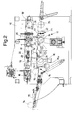
- an improved unit 11 for gluing an end edge of a log 14, 14', 14" according to the present invention is shown.
- References 14, 14', 14" shall be subsequently used to indicate both different logs and the same log with respect to respective different operative positions.
- log 14 shall refer to a log being fed and in the unwinding step
- log 14' shall refer to a log in the "timing” step
- log 14" shall refer to a "timed” log just about to receive a gluing substance.
- timing of a log is used to indicate a process that leads the final free edge of the log to be arranged in a determined angular position in a determined position during the forward movement of the log itself inside the machine.
- the improved gluing unit for an end edge log subject of the present invention is arranged in a machine for making logs.
- this machine generally provides for a bearing structure 12 provided with a feeding surface 13 sloped for feeding logs 14 - one after the other, indicated subsequently as mentioned above in the various operative positions also with 14', 14" for better understanding - which come from a preceding rereeling machine arranged upstream and not shown.
- a rotating sorting device 15 of the star type is provided for, having a series of pockets 15a, which receive the single logs 14 and feeds them one after the other towards the actual gluing unit 11 subject of the invention.
- Such gluing unit 11 provides for a first unwinding roller 16, motorised independent and arranged lower with respect to a feeder belt 17.
- the feeder belt 17 is arranged at the upper part above the gluing unit 11 and it is ring-extended between a pair of end-pulleys 18, 18'.
- an air nozzle 19 preferably at the upper part
- a sensor 20 preferably at the lower part, such as a photocell, such elements cooperating with the belt 17, unwind the final edge 29 of the log 14 according to a pre-established amount.
- Such configuration is for example shown in figure 1 .
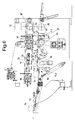
- a first section of the sloped surface 21 Arranged at the exit, i.e. subsequently downstream of the unwinding roller 16 is a first section of the sloped surface 21 which moves the log 14 to a timing unit 22, also motorised in an independent manner.
- Such timing unit 22 cooperates with the belt 17 to arrange the final edge 29 of the log 14' in a pre-established position during the forward movement of the log 14' itself.
- a second section of a sloped surface 23 which moves the timed log 14' towards a third roller 24, referred to as suction roller and also motorised in an independent manner.
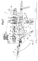
- This third suction roller 24 is connected to a vacuum source (not shown) and, for such purpose, and it is provided over its entire external lateral surface with suctioning holes adapted to withhold a pre-established portion of the final edge 29 of the log 14" as shown in figures 4 and 5 .
- this third suction roller 24 is arranged aligned below an upper roller 25, also motorised in an independent manner, which is moveable vertically towards and away from the suction roller 24 itself.
- glue dispenser device 27 Provided for beneath the feeder belt 17 and immediately after the suction roller 24 is any glue dispenser device 27.
- this glue dispenser 27 comprises a container 42 holding a gluing substance and a rod element 40 which is capable of cyclically being provided with glue on an upper pointed end 43 thereof.
- the abovementioned upper end 43, during or immediately before, the forward moving log 14" is at the glue dispenser 27, due to a mechanism not shown, performs a raising movement, of the vertical type, and comes into contact with the external surface of the log 14" in motion.
- part of the gluing substance held in the container 42 is released onto an external surface of the log 14" different from the final edge 29 previously withheld by the suction roller 24 as shown in figure 6 .
- an sloping evacuation surface 34 extended above which is the end part of the feeder belt 17, which ensures the constraint between the final end edge 29 of the log 14 and the log or roll itself, securely attaining the glue bond.
- timing unit 22 comprises according to the invention at least one belt or bend element 22, possibly suctioned and/or blown, moveable at a constant speed V22 opposite with respect to the forward movement speed V17 of the feeder belt 17.
- the abovementioned speed V22 is always lower than the speed V17 of the feeder belt 17.
- the value of the speed V22 can be set by a user according to the diameter of the logs 14 to be treated, at the beginning of each production cycle by operating on a dedicated motorisation.
- At least one belt or bend element 22 cooperates with the feeder belt 17 and positions the free end of the final edge 29 of the log 14' in a position arranged according to an angle ⁇ with respect to the vertical at the exit of the timing unit 22 itself.
- angle ⁇ depends on the diameter of the log 14', variable factor, and on the length of the second section of sloped surface 23, constant factor, in such a manner that when the log 14" itself reaches on the suction roller 24 by rolling on the second section of sloped surface 23, the free end of the final edge 29" is arranged at the zone of contact of the log 14" with the suction roller 24.
- the logs 14, wound almost to their final dimension, are fed on the sloped surface 13 coming from a preceding rereeling machine, arranged in the line.
- Each single log 14 is arranged in a pocket 15a of the rotating sorting device 15 and it is then fed according to a pre-established succession towards the gluing unit 11 of the present invention.
- the log 14 is arranged on the unwinding roller 16, positioned at the lower part, and it is withheld by the upper feeder belt 17.
- the unwinding roller 16 rotates in an anticlockwise direction, while the feeder belt 17 moves forward in such a manner to exert a given pressure on the log 14, though rotating it.
- the final edge 29 of the log 14 is moved, by rotating the log 14, to the blowing element 19.
- This blowing element 19 operates to open the final edge from the rest of the log 14 and the photocell 20 detects whether this opening occurs in a sufficient and proper manner.
- such photocell 20 reads the length of the edge 29 when in contact against the first flat section 21.
- the unwinding roller 16 stops and the continuous forward movement of the upper feeder belt 17 causes the log 14 to roll on the first section of the sloped surface 21 moving towards the at least one timing belt element 22.
- the free end of the final edge 29' of the log 14' identifies a given pre-selected angle ⁇ with respect to the vertical depending on the diameter of the log 14' and on the length of the second flat section 23 in such a manner that the log 14" comes into contact with the suction roller 24 with such free end of the final edge 29".
- the timed log 14" joins with the free end of the final edge 29" arranged at the zone of contact with the suction roller 24 (also referable to as the six o'clock position of the clock hands in figure 4 ).
- the log - indicated with 14" to distinguish the different step performed by the suction roller 24 with respect to the timing performed beforehand by the at least one belt element 22 - is arranged in the aforedescribed condition between the upper roller 25 and the suction roller 24.
- the suction roller 24 is driven to rotate in a clockwise direction and also the upper roller 25 is started to rotate in the clockwise direction.
- the final edge 29" is released by the suction roller 24 and the upper belt 17 causes the rolling of the log 14" on the sloping evacuation surface 34 in such a manner that the glue remains inside the log between the log itself and the final edge 29", attaching them mutually.
- a roller 35 arranged on the sloping evacuation surface 34, rotates causing the glued part to be transferred to the upper part of the log preventing the soiling of the surface itself.
- the abovementioned at least one belt element 22 is connected to a variable motor in such a manner to be able to guarantee the respective abovementioned function in presence of any diameter of the log being treated.
- the production cycle is more efficient eliminating a step wherein, in the known machines, the log did not move forward hence slowing down or requiring interruption of the feeding of the other logs.
- the abovementioned at least one timing belt element 22 is always in motion, it does not cause any, or causes very little, stresses of the mechanical/vibrational type deriving from a possible intermittent starting of the unit 22 itself.
- the at least one timing belt element 22 is always in motion, it does not have "on and off" transients, non-instantaneous and scarcely controllable events, hence arranging the final edge of the respective log in an extremely accurate manner thus optimising the subsequent gluing step.
- the improved gluing unit for an end edge log of the present invention thus conceived is susceptible to various modifications and variants, all falling within the same inventive concept; in addition, all details may be replaced by technically equivalent elements.
- the materials used, as well as the dimensions thereof, may vary depending on the technical requirements.
Landscapes
- Sanitary Thin Papers (AREA)
- Saccharide Compounds (AREA)
- Memory System Of A Hierarchy Structure (AREA)
- Replacement Of Web Rolls (AREA)
Applications Claiming Priority (1)
| Application Number | Priority Date | Filing Date | Title |
|---|---|---|---|
| IT000308A ITMI20080308A1 (it) | 2008-02-26 | 2008-02-26 | Gruppo incollatore perfezionato di un lembo d'estremita' di un log |
Publications (2)
| Publication Number | Publication Date |
|---|---|
| EP2096060A2 true EP2096060A2 (de) | 2009-09-02 |
| EP2096060A3 EP2096060A3 (de) | 2010-11-10 |
Family
ID=40291703
Family Applications (1)
| Application Number | Title | Priority Date | Filing Date |
|---|---|---|---|
| EP09153702A Withdrawn EP2096060A3 (de) | 2008-02-26 | 2009-02-26 | Klebstoffeinheit für eine Endkante eines Holzscheits |
Country Status (3)
| Country | Link |
|---|---|
| US (1) | US20090214757A1 (de) |
| EP (1) | EP2096060A3 (de) |
| IT (1) | ITMI20080308A1 (de) |
Cited By (3)
| Publication number | Priority date | Publication date | Assignee | Title |
|---|---|---|---|---|
| ITMI20100855A1 (it) * | 2010-05-13 | 2011-11-14 | Gambini Int Sa | Dispositivo per incollare il lembo finale di un rotolo di materiale nastriforme |
| IT201900003885A1 (it) * | 2019-03-18 | 2020-09-18 | Gambini Spa | Dispositivo incollatore di un lembo finale di un log. |
| RU2753967C2 (ru) * | 2017-03-22 | 2021-08-24 | Филип Моррис Продактс С.А. | Способ удаления клейкой этикетки с рулона и устройство для отделения клейкой этикетки от концевой части смотанного листа в рулоне |
Citations (1)
| Publication number | Priority date | Publication date | Assignee | Title |
|---|---|---|---|---|
| EP1440925A1 (de) | 2003-01-23 | 2004-07-28 | Giovanni Gambini | Klebevorrichtung für das Ende einer Rolle |
Family Cites Families (4)
| Publication number | Priority date | Publication date | Assignee | Title |
|---|---|---|---|---|
| IT1252896B (it) * | 1991-11-08 | 1995-07-05 | Perini Fabio Spa | Apparecchiatura perfezionata per incollare il lembo finale di rotoli di materiale nastriforme |
| IT1318995B1 (it) * | 2000-10-11 | 2003-09-19 | Giovanni Gambini | Gruppo incollatore di un lembo d'estremita' di un log |
| ITMI20041274A1 (it) * | 2004-06-24 | 2004-09-24 | Giovanni Gambini | Incollatore perfezionato di un lembo d'estremita' di un log e relativo metodo di incollatura |
| ITFI20070087A1 (it) * | 2007-04-13 | 2008-10-14 | Perini Fabio Spa | Metodo e dispositivo per la chiusura del lembo libero finale di un rotolo di materiale nastriforme e rotolo ottenuto |
-
2008
- 2008-02-26 IT IT000308A patent/ITMI20080308A1/it unknown
-
2009
- 2009-02-24 US US12/391,639 patent/US20090214757A1/en not_active Abandoned
- 2009-02-26 EP EP09153702A patent/EP2096060A3/de not_active Withdrawn
Patent Citations (1)
| Publication number | Priority date | Publication date | Assignee | Title |
|---|---|---|---|---|
| EP1440925A1 (de) | 2003-01-23 | 2004-07-28 | Giovanni Gambini | Klebevorrichtung für das Ende einer Rolle |
Cited By (7)
| Publication number | Priority date | Publication date | Assignee | Title |
|---|---|---|---|---|
| ITMI20100855A1 (it) * | 2010-05-13 | 2011-11-14 | Gambini Int Sa | Dispositivo per incollare il lembo finale di un rotolo di materiale nastriforme |
| EP2386510A1 (de) * | 2010-05-13 | 2011-11-16 | Gambini International S.A. | Vorrichtung zum Leimen der Endkante einer Rolle eines bandförmigen Materials |
| US8302650B2 (en) | 2010-05-13 | 2012-11-06 | Gambini International S.A. | Device for gluing the final edge of a log of a band-shaped material |
| RU2753967C2 (ru) * | 2017-03-22 | 2021-08-24 | Филип Моррис Продактс С.А. | Способ удаления клейкой этикетки с рулона и устройство для отделения клейкой этикетки от концевой части смотанного листа в рулоне |
| IT201900003885A1 (it) * | 2019-03-18 | 2020-09-18 | Gambini Spa | Dispositivo incollatore di un lembo finale di un log. |
| EP3712095A1 (de) * | 2019-03-18 | 2020-09-23 | GAMBINI S.p.A. | Vorrichtung zum verleimen eines endes einer rolle |
| US11325803B2 (en) | 2019-03-18 | 2022-05-10 | GAMBINI S.p.A. | Gluing device of an end edge of a log |
Also Published As
| Publication number | Publication date |
|---|---|
| EP2096060A3 (de) | 2010-11-10 |
| ITMI20080308A1 (it) | 2009-08-27 |
| US20090214757A1 (en) | 2009-08-27 |
Similar Documents
| Publication | Publication Date | Title |
|---|---|---|
| CN102317185B (zh) | 用于已卷绕幅材的卷筒的上胶装置 | |
| USRE37039E1 (en) | Apparatus for glueing the tail of a web to a log formed of the web material | |
| KR860001993B1 (ko) | 웨브의 스냅파단장치 | |
| EP1440925B1 (de) | Klebevorrichtung für das Ende einer Rolle | |
| US6682623B1 (en) | Device for gluing rolls of web material and associated method | |
| KR101025107B1 (ko) | 웨브재 롤을 형성하는 개량된 다시감기기계 | |
| KR20170002557A (ko) | 라벨 부착 기계 | |
| EP2096060A2 (de) | Klebstoffeinheit für eine Endkante eines Holzscheits | |
| US7640959B2 (en) | Device for gluing the end flap of a log, and corresponding gluing method | |
| US10279371B2 (en) | Gluing device of an end edge of a log and relative gluing method | |
| US4723720A (en) | Yarn end finding device | |
| EP1652804B1 (de) | Vorrichtung zum Aufbringen von Kleber auf ein Bahnende einer Wickelrolle und dazugehöriges Verfahren | |
| US6620241B2 (en) | Gluing unit of a tail end of a log | |
| IT9003583A1 (it) | Metodo per la sostituzione e la registrazione di materiale prestampato in nastro in una macchina operatrice. | |
| EP0132862B1 (de) | Anlage zum Identifizieren von Käsen durch Anbringen von bedrucktem Material | |
| EP2226280B1 (de) | Klebeanordnung zum Ankleben des Endes einer Papierrolle | |
| JPH0524728A (ja) | ロール原紙のコルゲートマシンへの供給装置 | |
| JPH0738060U (ja) | 残糸除去装置のボビン供給機構および除去後検査機構 |
Legal Events
| Date | Code | Title | Description |
|---|---|---|---|
| PUAI | Public reference made under article 153(3) epc to a published international application that has entered the european phase |
Free format text: ORIGINAL CODE: 0009012 |
|
| AK | Designated contracting states |
Kind code of ref document: A2 Designated state(s): AT BE BG CH CY CZ DE DK EE ES FI FR GB GR HR HU IE IS IT LI LT LU LV MC MK MT NL NO PL PT RO SE SI SK TR |
|
| AX | Request for extension of the european patent |
Extension state: AL BA RS |
|
| PUAL | Search report despatched |
Free format text: ORIGINAL CODE: 0009013 |
|
| AK | Designated contracting states |
Kind code of ref document: A3 Designated state(s): AT BE BG CH CY CZ DE DK EE ES FI FR GB GR HR HU IE IS IT LI LT LU LV MC MK MT NL NO PL PT RO SE SI SK TR |
|
| AX | Request for extension of the european patent |
Extension state: AL BA RS |
|
| 17P | Request for examination filed |
Effective date: 20110510 |
|
| AKX | Designation fees paid |
Designated state(s): AT BE BG CH CY CZ DE DK EE ES FI FR GB GR HR HU IE IS IT LI LT LU LV MC MK MT NL NO PL PT RO SE SI SK TR |
|
| STAA | Information on the status of an ep patent application or granted ep patent |
Free format text: STATUS: THE APPLICATION IS DEEMED TO BE WITHDRAWN |
|
| 18D | Application deemed to be withdrawn |
Effective date: 20140902 |