EP2096080B1 - Pistolet distributeur - Google Patents
Pistolet distributeur Download PDFInfo
- Publication number
- EP2096080B1 EP2096080B1 EP09002669A EP09002669A EP2096080B1 EP 2096080 B1 EP2096080 B1 EP 2096080B1 EP 09002669 A EP09002669 A EP 09002669A EP 09002669 A EP09002669 A EP 09002669A EP 2096080 B1 EP2096080 B1 EP 2096080B1
- Authority
- EP
- European Patent Office
- Prior art keywords
- spring
- valve
- dispensing
- dispensing valve
- delivery nozzle
- Prior art date
- Legal status (The legal status is an assumption and is not a legal conclusion. Google has not performed a legal analysis and makes no representation as to the accuracy of the status listed.)
- Active
Links
- 239000000446 fuel Substances 0.000 claims description 12
- 238000007789 sealing Methods 0.000 claims description 6
- 238000011010 flushing procedure Methods 0.000 claims description 4
- 230000005484 gravity Effects 0.000 claims description 3
- 239000007787 solid Substances 0.000 claims 4
- 238000007599 discharging Methods 0.000 claims 1
- 238000009434 installation Methods 0.000 claims 1
- 238000010926 purge Methods 0.000 abstract 1
- 239000012528 membrane Substances 0.000 description 11
- 239000003570 air Substances 0.000 description 3
- 239000007788 liquid Substances 0.000 description 2
- 239000012080 ambient air Substances 0.000 description 1
- 230000015572 biosynthetic process Effects 0.000 description 1
- 238000011109 contamination Methods 0.000 description 1
- 238000006073 displacement reaction Methods 0.000 description 1
- 238000005553 drilling Methods 0.000 description 1
- 230000007613 environmental effect Effects 0.000 description 1
- 239000012530 fluid Substances 0.000 description 1
- 210000000056 organ Anatomy 0.000 description 1
- 238000010079 rubber tapping Methods 0.000 description 1
- 230000001960 triggered effect Effects 0.000 description 1
- 238000011144 upstream manufacturing Methods 0.000 description 1
Images



Classifications
-
- B—PERFORMING OPERATIONS; TRANSPORTING
- B67—OPENING, CLOSING OR CLEANING BOTTLES, JARS OR SIMILAR CONTAINERS; LIQUID HANDLING
- B67D—DISPENSING, DELIVERING OR TRANSFERRING LIQUIDS, NOT OTHERWISE PROVIDED FOR
- B67D7/00—Apparatus or devices for transferring liquids from bulk storage containers or reservoirs into vehicles or into portable containers, e.g. for retail sale purposes
- B67D7/06—Details or accessories
- B67D7/42—Filling nozzles
- B67D7/44—Filling nozzles automatically closing
- B67D7/46—Filling nozzles automatically closing when liquid in container to be filled reaches a predetermined level
- B67D7/48—Filling nozzles automatically closing when liquid in container to be filled reaches a predetermined level by making use of air suction through an opening closed by the rising liquid
Definitions
- the invention relates to a fuel nozzle for a full-hose dispenser equipped with a dispensing pump which can be switched on and off, comprising a valve housing with a dispensing tube, dispensing valve and a hose connection, an actuating device with an actuating handle and an automatic shut-off device for overfill protection, according to the preamble of claim 1 ,
- the dispensing medium located in the interior of the hollow valve spindle collects after completion of the dispensing operation, when the fuel nozzle is suspended in approximately vertical position to the dispenser in the then lower part of the valve housing in the vicinity of the dispensing valve and can when removing the fuel nozzle at the beginning another tapping when uncontrolled leakage from the inclined nozzle, which can lead to contamination and harmful environmental effects.
- the object of the invention is to improve a fuel nozzle of the type mentioned in that contained in the hollow valve stem Zapfftüsstechnik after completion of or at the beginning of a new dispensing operation does not leak uncontrollably.
- the invention further provides that in the valve stem, a stop is formed, against which the pull rod rests spring-loaded with dissolved operating handle.
- the stop is designed as an additional sealing point and / or as a throttle point for the rinsing cycle. It can be provided that upon actuation of the actuating handle, an opening of the first stop and then the opening gap takes place.
- the invention preferably provides that the first closing element is fixedly connected to a bearing shaft acted upon by the full hose spring and the second closing element is spring-loaded and axially displaceably guided on the bearing shaft.
- the second closing element is firmly connected to a bearing shaft acted upon by the full hose spring and the first closing element is spring-loaded and axially displaceably guided on the bearing shaft.
- the invention preferably provides that between the vacuum chamber and the fill level sensor line, a safety valve is arranged, the valve body closes automatically in an upwardly facing position of the discharge pipe due to gravity.
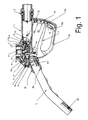
- Fig. 1 shows a fuel nozzle according to the invention in section, with a valve housing 1, an inlet adapter 2, with which a hose, not shown, for connection to a pump or discharge pump is to be connected, an outlet pipe 3 and an operating handle 4th
- a dispensing valve seat 14 is formed in the interior of the valve housing 1 and an associated, loaded by a Vollschlauchfeder 13 dispensing valve body 10, 11 and an axially displaceable hollow valve spindle 6 is arranged, which is guided in a substantially cylindrical bearing housing 9.
- a connected to the operating handle 4 pull rod 5 is guided.
- the valve spindle 6 and the pull rod 5 can be coupled and uncoupled by a locking device belonging to an automatic shut-off 15, 17, 18 with locking rollers 16.
- the membrane 15 is connected to a diaphragm cage 18 with compensating clearance, in which the locking rollers 16 store.
- the diaphragm pulls out the diaphragm cage 18 transversely to the longitudinal axis of the valve stem 6, so that the membrane rollers 16 from a Quemut 5c of the tie rod 5 and Move a Quemut 6a of the valve stem 6 out.
- a closing spring 7, which acts on the valve spindle 6, then ensures despite pulled operating handle 4 that the valve spindle 6 rests against the two closing elements 10, 11 of the dispensing valve body and against the flow of Zapfmediums sealingly against the dispensing valve seat 14.
- the closing spring 8 presses the pull rod 5 against a stop 6b, which is formed in a preferred embodiment as an annular sealing point.
- a stop 6b which is formed in a preferred embodiment as an annular sealing point.
- actuating handle 4 When pulling the rotatably mounted on a bearing axis 1a on the housing 1 and sealed with seal 21 actuating handle 4 engages a hand lever pin 4a on a front edge 5a of the longitudinal groove 5b of the tie rod 5 and pushes them together with the valve stem 6 together with in a transverse groove 5c the tie rod 5 overlapping locking rollers 16 after (in Fig. 2 to the left) and thus biases the two closing springs 7, 8.
- a first step ( Fig. 3 ) only the pull rod 5 with the locking rollers 16 by the already mentioned measure of about 0.5 mm is axially moved until the locking rollers 16 come to rest on a front edge of a transverse groove 6a of the valve stem 6. During this displacement, the pull rod 5 is lifted off the stop 6b on the valve spindle 6, thereby opening the first seal in the region of the stop 6b.
- a second step ( Fig. 4 ) the pull rod 5 and the valve stem 6 are moved together axially, so that the closing organ spring 12 is relieved until the second closing element 10 abuts a system 11 a on the bearing shaft 13a, wherein the second closing element 10 lifts from the first closing element 11 and forms the opening gap 10a, so that a second seal is opened.
- a third step ( Fig. 5 ) the pull rod 5 and the valve spindle 6 are moved axially together with the locking rollers 16, whereby the closing springs 7, 8 are further tensioned and the dispensing valve body 10, 11 completely lifts off from the dispensing valve seat 14.
- a gap 14b is formed through which the dispensing medium passes at a high flow rate, so that in the gap 14b, a first low pressure area is formed.
- a flushing circuit is driven through this low-pressure area, which is formed on the inlet side by an over a part of the circumference of the bearing housing 9 extending annular channel 9c, which communicates with the dispensing medium, and an axial channel, a Spellerschohrung 9a, a filter point 9b, the is formed by a gap between the bearing housing 9 and the valve spindle 6, and continues axially up to the stop 6b and the opening gap 10a.
- the membrane 15 is now pulled against the restoring force of the diaphragm spring 17 in the direction of the vacuum chamber 15 a and pulls over the diaphragm cage 18, the locking rollers 16 from the transverse grooves 5 c, 6 a of pull rod 5 and valve spindle. 6
- the closing spring 7 then ensures despite pulled operating handle 4 that the valve stem 6 (to the right) moves against the dispensing valve body 10, 11 and this brings against the sealing seat 14 to the plant, so that the flow of the Zapfmediums is interrupted. In this case, the opening gap 10a is closed against the force of the closing member spring 12.
- the full tube spring 13 ensures that the dispensing valve body 10, 11 against the dispensing valve seat 14th comes to rest, so that it prevents the tube emptied or air penetrates ( Fig. 6 ).
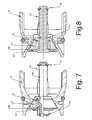
- Fig. 7 shows in enlarged scale a preferred embodiment of the dispensing valve with dispensing valve seat 14 and dispensing valve body 10, 11.
- the full tube spring 13 is supported on a stopper 22 which is fixedly connected to the first closing element 11 via the bearing shaft 13a and biases the dispensing valve body in the direction the discharge valve seat 14, so that the full hose tightness is ensured.
- the opening gap 10a between the two closing elements 10, 11 can be clearly seen.
- Fig. 8 shows a variant of the dispensing valve, which also ensures the said function of full hose tightness.
- the full hose spring 13 is supported on the stop 22, which is located on the bearing shaft 13 a, which in turn is firmly connected to the second closing element 10.
- the spring 12 causes the formation of the opening gap 10a in the unloaded state.
- the dispensing valve according to the invention has an integrated drop collecting chamber 25 which collects in a mounting position of the dispensing valve, in which the outlet pipe 3 faces upwards, externally attached to the outlet pipe dispensing medium and dispensed in a subsequent dispensing operation through a constriction 3c again.
- Fig. 2 shows that between the vacuum chamber 15a and the level sensor line 3b, a safety valve 19 is arranged, the valve body 19a (ball, both open and closed position shown) in an upwardly facing position of the discharge pipe 3 by gravity automatically closes.
Landscapes
- Engineering & Computer Science (AREA)
- Mechanical Engineering (AREA)
- Mechanically-Actuated Valves (AREA)
- Percussion Or Vibration Massage (AREA)
- Jet Pumps And Other Pumps (AREA)
- Feeding And Controlling Fuel (AREA)
- Preventing Unauthorised Actuation Of Valves (AREA)
- Lift Valve (AREA)
- Gas Separation By Absorption (AREA)
- Loading And Unloading Of Fuel Tanks Or Ships (AREA)
Claims (7)
- Pistolet distributeur de carburant pour une installation de distribution avec flexible pour faire le plein équipée d'une pompe de distribution pouvant être mise en et hors service, avec un boîtier de soupape (1) présentant un tuyau d'évacuation (3), une soupape de distribution (11, 12, 14) et un raccord de tuyau, un dispositif d'actionnement avec une manette d'actionnement (4) et un dispositif automatique d'arrêt (15, 17, 18) pour le dispositif antidébordement, dans le boîtier de soupape (1) étant réalisé un siège de soupape de distribution (14) et étant disposé un corps de soupape de distribution (10, 11) afférent, sollicité par un ressort de flexible pour faire le plein (13) en direction d'une position de fermeture, le corps de soupape de distribution (10, 11) étant sollicité dans le sens de fermeture par une tige de soupape (6) creuse pouvant être actionnée par la manette d'actionnement (4), dans laquelle est guidée une tige de traction (5) reliée à la manette d'actionnement (4), la tige de soupape (6) et la tige de traction (5) pouvant être couplées et découplées par un dispositif d'encliquetage (16) associé au dispositif automatique d'arrêt (15, 17, 18), le dispositif automatique d'arrêt présentant une chambre de dépression (15a) avec une conduite de capteur de niveau (3b) et avec une conduite de dépression (1c) débouchant dans la zone du siège de soupape de distribution (14) ainsi qu'une chambre de compensation de pression (15b) et une membrane (15) séparant la chambre, actionnant le dispositif d'encliquetage, la membrane présentant un ressort de membrane (17), avec lequel la dépression d'arrêt du dispositif automatique d'arrêt peut être réglée, la tige de soupape (6) étant guidée dans un logement de palier (9), dans lequel des ressorts de fermeture (7, 8) pour la tige de soupape (6) et la tige de traction (5) sont aussi logés,
caractérisé en ce que le corps de soupape de distribution présente deux éléments de fermeture (10, 11) sollicités par ressort, pouvant être déplacés axialement l'un vers l'autre, entre lesquels peut être engendrée une fente d'ouverture (10a) dans la zone du siège de soupape de distribution (14), un premier élément de fermeture (11) coopérant avec le siège de soupape de distribution (14), et un circuit de rinçage étant formé au travers du logement de palier (9), entraîné par une dépression agissant dans la zone de la fente d'ouverture (10a) en cas de soupape de distribution ouverte, le circuit de rinçage pouvant être rendu étanche par un second élément de fermeture (10). - Pistolet distributeur selon la revendication 1, caractérisé en ce qu'une butée (6b) est formée sur la tige de soupape (6), contre laquelle la tige de traction (5) repose sollicitée par le ressort de fermeture (8) en cas de manette d'actionnement (4) détachée.
- Pistolet distributeur selon la revendication 2, caractérisé en ce que la butée (6b) est réalisée en tant que zone étanche supplémentaire et/ou comme une zone d'étranglement pour le circuit de rinçage.
- Pistolet distributeur selon la revendication 2 ou 3, caractérisé en ce que, lors de l'actionnement de la manette d'actionnement (4), une ouverture tout d'abord de la butée (6b) puis de la fente d'ouverture (10a) est effectuée.
- Pistolet distributeur selon l'une quelconque des revendications précédentes, caractérisé en ce que le premier élément de fermeture (11) est relié fixement à une queue de palier (13a) sollicitée par le ressort de flexible plein (13) et le second élément de fermeture (10) est guidé sollicité par ressort (12) et axialement limité en déplacement sur la queue de palier (13a).
- Pistolet distributeur selon l'une quelconque des revendications précédentes, caractérisé en ce que le second élément de fermeture (10) est relié fixement à une queue de palier (13a) sollicitée par le ressort de flexible pour faire le plein (13) et le premier élément de fermeture (11) est guidé sollicité par ressort (12) et axialement limité en déplacement sur la queue de palier (13a).
- Pistolet distributeur selon l'une quelconque des revendications précédentes, caractérisé en ce que, entre la chambre de dépression (15a) et la conduite de capteur de niveau (3b), est disposée une soupape de sûreté (19), dont le corps de soupape (19a) se ferme automatiquement en raison de la force de gravité dans une position tournée vers le haut du tuyau d'évacuation (3).
Priority Applications (1)
| Application Number | Priority Date | Filing Date | Title |
|---|---|---|---|
| PL09002669T PL2096080T3 (pl) | 2008-02-25 | 2009-02-25 | Końcówka węża do napełniania paliwem |
Applications Claiming Priority (1)
| Application Number | Priority Date | Filing Date | Title |
|---|---|---|---|
| DE102008010988A DE102008010988B3 (de) | 2008-02-25 | 2008-02-25 | Zapfpistole |
Publications (2)
| Publication Number | Publication Date |
|---|---|
| EP2096080A1 EP2096080A1 (fr) | 2009-09-02 |
| EP2096080B1 true EP2096080B1 (fr) | 2011-04-13 |
Family
ID=40756217
Family Applications (1)
| Application Number | Title | Priority Date | Filing Date |
|---|---|---|---|
| EP09002669A Active EP2096080B1 (fr) | 2008-02-25 | 2009-02-25 | Pistolet distributeur |
Country Status (7)
| Country | Link |
|---|---|
| EP (1) | EP2096080B1 (fr) |
| AT (1) | ATE505433T1 (fr) |
| DE (2) | DE102008010988B3 (fr) |
| DK (1) | DK2096080T3 (fr) |
| ES (1) | ES2363193T3 (fr) |
| PL (1) | PL2096080T3 (fr) |
| PT (1) | PT2096080E (fr) |
Cited By (1)
| Publication number | Priority date | Publication date | Assignee | Title |
|---|---|---|---|---|
| EP4234481A1 (fr) | 2022-02-23 | 2023-08-30 | ELAFLEX HIBY GmbH & Co. KG | Soupape de soutirage |
Families Citing this family (5)
| Publication number | Priority date | Publication date | Assignee | Title |
|---|---|---|---|---|
| US8752597B2 (en) | 2008-09-17 | 2014-06-17 | Franklin Fueling Systems, Inc. | Fuel dispensing nozzle |
| US8371341B2 (en) | 2009-09-24 | 2013-02-12 | Deleware Capital Formation, Inc. | Magnetically actuated vapor recovery valve |
| EP2316685A1 (fr) | 2009-10-21 | 2011-05-04 | Inergy Automotive Systems Research (Société Anonyme) | Système de remplissage amélioré pour conteneur fluide véhiculaire |
| DK2386520T3 (da) | 2010-05-14 | 2013-05-06 | Elaflex Hiby Tanktechnik Gmbh & Co | Påfyldningsventil |
| DK2428485T3 (en) | 2010-09-13 | 2014-03-17 | Elaflex Hiby Tanktechnik Gmbh & Co Kg | dispensing nozzle |
Family Cites Families (2)
| Publication number | Priority date | Publication date | Assignee | Title |
|---|---|---|---|---|
| LU43573A1 (fr) * | 1962-04-19 | 1963-06-17 | ||
| DE3528612C1 (de) * | 1985-08-09 | 1986-12-11 | Karlheinz 2000 Hamburg Ehlers | Zapfpistole fuer Kraftstoff mit fuellhoehenabhaengiger Abschaltautomatik und pumpendruckabhaengiger Sicherheitsvorrichtung |
-
2008
- 2008-02-25 DE DE102008010988A patent/DE102008010988B3/de not_active Expired - Fee Related
-
2009
- 2009-02-25 AT AT09002669T patent/ATE505433T1/de active
- 2009-02-25 DE DE502009000514T patent/DE502009000514D1/de active Active
- 2009-02-25 PT PT09002669T patent/PT2096080E/pt unknown
- 2009-02-25 EP EP09002669A patent/EP2096080B1/fr active Active
- 2009-02-25 ES ES09002669T patent/ES2363193T3/es active Active
- 2009-02-25 DK DK09002669.1T patent/DK2096080T3/da active
- 2009-02-25 PL PL09002669T patent/PL2096080T3/pl unknown
Cited By (2)
| Publication number | Priority date | Publication date | Assignee | Title |
|---|---|---|---|---|
| EP4234481A1 (fr) | 2022-02-23 | 2023-08-30 | ELAFLEX HIBY GmbH & Co. KG | Soupape de soutirage |
| WO2023161205A1 (fr) | 2022-02-23 | 2023-08-31 | Elaflex Hiby Gmbh & Co. Kg | Buse de carburant |
Also Published As
| Publication number | Publication date |
|---|---|
| ATE505433T1 (de) | 2011-04-15 |
| DK2096080T3 (da) | 2011-07-25 |
| DE502009000514D1 (de) | 2011-05-26 |
| DE102008010988B3 (de) | 2009-07-16 |
| PL2096080T3 (pl) | 2011-09-30 |
| ES2363193T3 (es) | 2011-07-26 |
| EP2096080A1 (fr) | 2009-09-02 |
| PT2096080E (pt) | 2011-06-28 |
Similar Documents
| Publication | Publication Date | Title |
|---|---|---|
| EP2386520B1 (fr) | Buse de distribution | |
| EP2096080B1 (fr) | Pistolet distributeur | |
| DE2362422A1 (de) | Selbsttaetig absperrende zapfpistole | |
| DE2547912A1 (de) | Rohrleitungssystem mit schutzvorrichtung gegen bruch und undichtigkeit | |
| EP2428485B1 (fr) | Buse de distribution | |
| EP1468220A1 (fr) | Garniture | |
| EP2453804B1 (fr) | Instrument commandé par gaz comprimé, en particulier instrument chirurgical | |
| DE19907840A1 (de) | Leichtflüssigkeitsabscheider mit Ablaufsperre | |
| AT408970B (de) | Vorrichtung zum verhindern des überfüllens eines kraftstofftankes | |
| EP0477773A2 (fr) | Dispositif et méthode pour remplir un réservoir avec une substance plus ou moins visqueuse | |
| DE102008054493A1 (de) | Einfüllstutzen mit automatischem Tankverschluss | |
| DE3304390A1 (de) | Zapfpistole fuer vollschlauch-zapfanlagen | |
| EP4355685A1 (fr) | Pistolet de distribution | |
| DE102007034581B4 (de) | Luftleitungsanschluss | |
| EP4222105B1 (fr) | Pistolet de soutirage à fermeture automatique | |
| WO2015128326A1 (fr) | Soupape de réduction de pression pour une installation d'extinction d'incendie, ainsi qu'installation d'extinction d'incendie équipée d'une soupape de réduction de pression de ce type | |
| EP0140106A2 (fr) | Soupape de soutirage pour prélever des gaz combustibles condensés d'un réservoir de stockage | |
| EP3974374B1 (fr) | Buse de distribution avec interrupteur entre deux débits maximaux | |
| EP4514740B1 (fr) | Soupape de soutirage | |
| DE1798056C (de) | Vorrichtung zur Steuerung der durch eine Falleitung in einen Behalter stro menden Flussigkeitsmenge | |
| DE202006001035U1 (de) | Anordnung zur Übernahme, Messung und Abgrenzung von Milchmengen aus einem Bereitstellungsbehälter in einen Sammeltank | |
| DE9402680U1 (de) | Anschlußadapter für die Kältemittelbefüllung oder -entnahme bei einer Kältemittelanlage | |
| DE20110760U1 (de) | Einfüllstutzen für einen Treibstofftank | |
| EP3464165A1 (fr) | Installation et procédé pour distribuer un liquide contenu dans un camion-citerne | |
| EP3657073A1 (fr) | Clapet anti-retour |
Legal Events
| Date | Code | Title | Description |
|---|---|---|---|
| PUAI | Public reference made under article 153(3) epc to a published international application that has entered the european phase |
Free format text: ORIGINAL CODE: 0009012 |
|
| AK | Designated contracting states |
Kind code of ref document: A1 Designated state(s): AT BE BG CH CY CZ DE DK EE ES FI FR GB GR HR HU IE IS IT LI LT LU LV MC MK MT NL NO PL PT RO SE SI SK TR |
|
| AX | Request for extension of the european patent |
Extension state: AL BA RS |
|
| 17P | Request for examination filed |
Effective date: 20100107 |
|
| AKX | Designation fees paid |
Designated state(s): AT BE BG CH CY CZ DE DK EE ES FI FR GB GR HR HU IE IS IT LI LT LU LV MC MK MT NL NO PL PT RO SE SI SK TR |
|
| AXX | Extension fees paid |
Extension state: RS Payment date: 20100202 |
|
| GRAP | Despatch of communication of intention to grant a patent |
Free format text: ORIGINAL CODE: EPIDOSNIGR1 |
|
| RIC1 | Information provided on ipc code assigned before grant |
Ipc: B67D 7/48 20100101AFI20100907BHEP |
|
| GRAS | Grant fee paid |
Free format text: ORIGINAL CODE: EPIDOSNIGR3 |
|
| GRAA | (expected) grant |
Free format text: ORIGINAL CODE: 0009210 |
|
| AK | Designated contracting states |
Kind code of ref document: B1 Designated state(s): AT BE BG CH CY CZ DE DK EE ES FI FR GB GR HR HU IE IS IT LI LT LU LV MC MK MT NL NO PL PT RO SE SI SK TR |
|
| AX | Request for extension of the european patent |
Extension state: RS |
|
| REG | Reference to a national code |
Ref country code: GB Ref legal event code: FG4D Free format text: NOT ENGLISH |
|
| REG | Reference to a national code |
Ref country code: CH Ref legal event code: EP |
|
| REG | Reference to a national code |
Ref country code: IE Ref legal event code: FG4D Free format text: LANGUAGE OF EP DOCUMENT: GERMAN |
|
| REF | Corresponds to: |
Ref document number: 502009000514 Country of ref document: DE Date of ref document: 20110526 Kind code of ref document: P |
|
| REG | Reference to a national code |
Ref country code: DE Ref legal event code: R096 Ref document number: 502009000514 Country of ref document: DE Effective date: 20110526 |
|
| REG | Reference to a national code |
Ref country code: PT Ref legal event code: SC4A Free format text: AVAILABILITY OF NATIONAL TRANSLATION Effective date: 20110614 |
|
| REG | Reference to a national code |
Ref country code: SE Ref legal event code: TRGR |
|
| REG | Reference to a national code |
Ref country code: NL Ref legal event code: T3 |
|
| REG | Reference to a national code |
Ref country code: DK Ref legal event code: T3 |
|
| REG | Reference to a national code |
Ref country code: ES Ref legal event code: FG2A Ref document number: 2363193 Country of ref document: ES Kind code of ref document: T3 Effective date: 20110726 |
|
| REG | Reference to a national code |
Ref country code: GR Ref legal event code: EP Ref document number: 20110401523 Country of ref document: GR Effective date: 20110714 |
|
| LTIE | Lt: invalidation of european patent or patent extension |
Effective date: 20110413 |
|
| REG | Reference to a national code |
Ref country code: PL Ref legal event code: T3 |
|
| PG25 | Lapsed in a contracting state [announced via postgrant information from national office to epo] |
Ref country code: NO Free format text: LAPSE BECAUSE OF FAILURE TO SUBMIT A TRANSLATION OF THE DESCRIPTION OR TO PAY THE FEE WITHIN THE PRESCRIBED TIME-LIMIT Effective date: 20110713 Ref country code: LT Free format text: LAPSE BECAUSE OF FAILURE TO SUBMIT A TRANSLATION OF THE DESCRIPTION OR TO PAY THE FEE WITHIN THE PRESCRIBED TIME-LIMIT Effective date: 20110413 Ref country code: HR Free format text: LAPSE BECAUSE OF FAILURE TO SUBMIT A TRANSLATION OF THE DESCRIPTION OR TO PAY THE FEE WITHIN THE PRESCRIBED TIME-LIMIT Effective date: 20110413 |
|
| REG | Reference to a national code |
Ref country code: IE Ref legal event code: FD4D |
|
| PG25 | Lapsed in a contracting state [announced via postgrant information from national office to epo] |
Ref country code: FI Free format text: LAPSE BECAUSE OF FAILURE TO SUBMIT A TRANSLATION OF THE DESCRIPTION OR TO PAY THE FEE WITHIN THE PRESCRIBED TIME-LIMIT Effective date: 20110413 Ref country code: CY Free format text: LAPSE BECAUSE OF FAILURE TO SUBMIT A TRANSLATION OF THE DESCRIPTION OR TO PAY THE FEE WITHIN THE PRESCRIBED TIME-LIMIT Effective date: 20110413 Ref country code: IS Free format text: LAPSE BECAUSE OF FAILURE TO SUBMIT A TRANSLATION OF THE DESCRIPTION OR TO PAY THE FEE WITHIN THE PRESCRIBED TIME-LIMIT Effective date: 20110813 Ref country code: LV Free format text: LAPSE BECAUSE OF FAILURE TO SUBMIT A TRANSLATION OF THE DESCRIPTION OR TO PAY THE FEE WITHIN THE PRESCRIBED TIME-LIMIT Effective date: 20110413 Ref country code: SI Free format text: LAPSE BECAUSE OF FAILURE TO SUBMIT A TRANSLATION OF THE DESCRIPTION OR TO PAY THE FEE WITHIN THE PRESCRIBED TIME-LIMIT Effective date: 20110413 |
|
| PG25 | Lapsed in a contracting state [announced via postgrant information from national office to epo] |
Ref country code: CZ Free format text: LAPSE BECAUSE OF FAILURE TO SUBMIT A TRANSLATION OF THE DESCRIPTION OR TO PAY THE FEE WITHIN THE PRESCRIBED TIME-LIMIT Effective date: 20110413 Ref country code: EE Free format text: LAPSE BECAUSE OF FAILURE TO SUBMIT A TRANSLATION OF THE DESCRIPTION OR TO PAY THE FEE WITHIN THE PRESCRIBED TIME-LIMIT Effective date: 20110413 Ref country code: IE Free format text: LAPSE BECAUSE OF FAILURE TO SUBMIT A TRANSLATION OF THE DESCRIPTION OR TO PAY THE FEE WITHIN THE PRESCRIBED TIME-LIMIT Effective date: 20110413 |
|
| PLBE | No opposition filed within time limit |
Free format text: ORIGINAL CODE: 0009261 |
|
| STAA | Information on the status of an ep patent application or granted ep patent |
Free format text: STATUS: NO OPPOSITION FILED WITHIN TIME LIMIT |
|
| PG25 | Lapsed in a contracting state [announced via postgrant information from national office to epo] |
Ref country code: RO Free format text: LAPSE BECAUSE OF FAILURE TO SUBMIT A TRANSLATION OF THE DESCRIPTION OR TO PAY THE FEE WITHIN THE PRESCRIBED TIME-LIMIT Effective date: 20110413 Ref country code: SK Free format text: LAPSE BECAUSE OF FAILURE TO SUBMIT A TRANSLATION OF THE DESCRIPTION OR TO PAY THE FEE WITHIN THE PRESCRIBED TIME-LIMIT Effective date: 20110413 |
|
| 26N | No opposition filed |
Effective date: 20120116 |
|
| REG | Reference to a national code |
Ref country code: DE Ref legal event code: R097 Ref document number: 502009000514 Country of ref document: DE Effective date: 20120116 |
|
| BERE | Be: lapsed |
Owner name: ELAFLEX TANKSTELLENTECHNIK G.M.B.H. & CO. Effective date: 20120228 |
|
| PG25 | Lapsed in a contracting state [announced via postgrant information from national office to epo] |
Ref country code: MC Free format text: LAPSE BECAUSE OF NON-PAYMENT OF DUE FEES Effective date: 20120229 |
|
| PG25 | Lapsed in a contracting state [announced via postgrant information from national office to epo] |
Ref country code: BE Free format text: LAPSE BECAUSE OF NON-PAYMENT OF DUE FEES Effective date: 20120228 |
|
| PG25 | Lapsed in a contracting state [announced via postgrant information from national office to epo] |
Ref country code: MK Free format text: LAPSE BECAUSE OF FAILURE TO SUBMIT A TRANSLATION OF THE DESCRIPTION OR TO PAY THE FEE WITHIN THE PRESCRIBED TIME-LIMIT Effective date: 20110413 |
|
| PG25 | Lapsed in a contracting state [announced via postgrant information from national office to epo] |
Ref country code: BG Free format text: LAPSE BECAUSE OF FAILURE TO SUBMIT A TRANSLATION OF THE DESCRIPTION OR TO PAY THE FEE WITHIN THE PRESCRIBED TIME-LIMIT Effective date: 20110713 |
|
| PG25 | Lapsed in a contracting state [announced via postgrant information from national office to epo] |
Ref country code: MT Free format text: LAPSE BECAUSE OF FAILURE TO SUBMIT A TRANSLATION OF THE DESCRIPTION OR TO PAY THE FEE WITHIN THE PRESCRIBED TIME-LIMIT Effective date: 20110413 |
|
| REG | Reference to a national code |
Ref country code: CH Ref legal event code: PL |
|
| PG25 | Lapsed in a contracting state [announced via postgrant information from national office to epo] |
Ref country code: CH Free format text: LAPSE BECAUSE OF NON-PAYMENT OF DUE FEES Effective date: 20130228 Ref country code: LI Free format text: LAPSE BECAUSE OF NON-PAYMENT OF DUE FEES Effective date: 20130228 |
|
| PG25 | Lapsed in a contracting state [announced via postgrant information from national office to epo] |
Ref country code: LU Free format text: LAPSE BECAUSE OF NON-PAYMENT OF DUE FEES Effective date: 20120225 |
|
| PG25 | Lapsed in a contracting state [announced via postgrant information from national office to epo] |
Ref country code: HU Free format text: LAPSE BECAUSE OF FAILURE TO SUBMIT A TRANSLATION OF THE DESCRIPTION OR TO PAY THE FEE WITHIN THE PRESCRIBED TIME-LIMIT Effective date: 20090225 |
|
| REG | Reference to a national code |
Ref country code: FR Ref legal event code: PLFP Year of fee payment: 8 |
|
| REG | Reference to a national code |
Ref country code: FR Ref legal event code: PLFP Year of fee payment: 9 |
|
| REG | Reference to a national code |
Ref country code: FR Ref legal event code: PLFP Year of fee payment: 10 |
|
| REG | Reference to a national code |
Ref country code: NL Ref legal event code: HC Owner name: ELAFLEX HIBY GMBH & CO. KG.; DE Free format text: DETAILS ASSIGNMENT: CHANGE OF OWNER(S), CHANGE OF OWNER(S) NAME; FORMER OWNER NAME: ELAFLEX-HIBY TANKTECHNIK GMBH & CO. KG Effective date: 20201119 Ref country code: NL Ref legal event code: PD Owner name: ELAFLEX-HIBY TANKTECHNIK GMBH & CO. KG; DE Free format text: DETAILS ASSIGNMENT: CHANGE OF OWNER(S), MERGE; FORMER OWNER NAME: ELAFLEX-HIBY TANKTECHNIK GMBH & CO. Effective date: 20201119 |
|
| REG | Reference to a national code |
Ref country code: GB Ref legal event code: 732E Free format text: REGISTERED BETWEEN 20201210 AND 20201216 |
|
| REG | Reference to a national code |
Ref country code: DE Ref legal event code: R082 Ref document number: 502009000514 Country of ref document: DE Representative=s name: GLAWE DELFS MOLL PARTNERSCHAFT MBB VON PATENT-, DE Ref country code: DE Ref legal event code: R081 Ref document number: 502009000514 Country of ref document: DE Owner name: ELAFLEX HIBY GMBH & CO. KG, DE Free format text: FORMER OWNER: ELAFLEX TANKSTELLENTECHNIK GMBH & CO, 22525 HAMBURG, DE |
|
| REG | Reference to a national code |
Ref country code: ES Ref legal event code: PC2A Owner name: ELAFLEX HIBY GMBH & CO. KG Effective date: 20210322 |
|
| REG | Reference to a national code |
Ref country code: AT Ref legal event code: HC Ref document number: 505433 Country of ref document: AT Kind code of ref document: T Owner name: ELAFLEX HIBY GMBH & CO. KG, DE Effective date: 20210323 |
|
| PGFP | Annual fee paid to national office [announced via postgrant information from national office to epo] |
Ref country code: GB Payment date: 20220221 Year of fee payment: 14 Ref country code: DK Payment date: 20220221 Year of fee payment: 14 Ref country code: DE Payment date: 20220222 Year of fee payment: 14 Ref country code: AT Payment date: 20220215 Year of fee payment: 14 |
|
| PGFP | Annual fee paid to national office [announced via postgrant information from national office to epo] |
Ref country code: TR Payment date: 20220215 Year of fee payment: 14 Ref country code: SE Payment date: 20220221 Year of fee payment: 14 Ref country code: PT Payment date: 20220218 Year of fee payment: 14 Ref country code: NL Payment date: 20220216 Year of fee payment: 14 Ref country code: IT Payment date: 20220228 Year of fee payment: 14 Ref country code: GR Payment date: 20220216 Year of fee payment: 14 Ref country code: FR Payment date: 20220221 Year of fee payment: 14 Ref country code: ES Payment date: 20220318 Year of fee payment: 14 |
|
| REG | Reference to a national code |
Ref country code: DE Ref legal event code: R119 Ref document number: 502009000514 Country of ref document: DE |
|
| REG | Reference to a national code |
Ref country code: DK Ref legal event code: EBP Effective date: 20230228 |
|
| REG | Reference to a national code |
Ref country code: SE Ref legal event code: EUG |
|
| REG | Reference to a national code |
Ref country code: NL Ref legal event code: MM Effective date: 20230301 |
|
| REG | Reference to a national code |
Ref country code: AT Ref legal event code: MM01 Ref document number: 505433 Country of ref document: AT Kind code of ref document: T Effective date: 20230225 |
|
| GBPC | Gb: european patent ceased through non-payment of renewal fee |
Effective date: 20230225 |
|
| PG25 | Lapsed in a contracting state [announced via postgrant information from national office to epo] |
Ref country code: SE Free format text: LAPSE BECAUSE OF NON-PAYMENT OF DUE FEES Effective date: 20230226 Ref country code: PT Free format text: LAPSE BECAUSE OF NON-PAYMENT OF DUE FEES Effective date: 20230825 Ref country code: AT Free format text: LAPSE BECAUSE OF NON-PAYMENT OF DUE FEES Effective date: 20230225 |
|
| PG25 | Lapsed in a contracting state [announced via postgrant information from national office to epo] |
Ref country code: NL Free format text: LAPSE BECAUSE OF NON-PAYMENT OF DUE FEES Effective date: 20230301 Ref country code: GR Free format text: LAPSE BECAUSE OF NON-PAYMENT OF DUE FEES Effective date: 20230906 |
|
| PG25 | Lapsed in a contracting state [announced via postgrant information from national office to epo] |
Ref country code: GB Free format text: LAPSE BECAUSE OF NON-PAYMENT OF DUE FEES Effective date: 20230225 |
|
| PG25 | Lapsed in a contracting state [announced via postgrant information from national office to epo] |
Ref country code: IT Free format text: LAPSE BECAUSE OF NON-PAYMENT OF DUE FEES Effective date: 20230225 Ref country code: GB Free format text: LAPSE BECAUSE OF NON-PAYMENT OF DUE FEES Effective date: 20230225 Ref country code: FR Free format text: LAPSE BECAUSE OF NON-PAYMENT OF DUE FEES Effective date: 20230228 Ref country code: DK Free format text: LAPSE BECAUSE OF NON-PAYMENT OF DUE FEES Effective date: 20230228 Ref country code: DE Free format text: LAPSE BECAUSE OF NON-PAYMENT OF DUE FEES Effective date: 20230901 |
|
| PG25 | Lapsed in a contracting state [announced via postgrant information from national office to epo] |
Ref country code: ES Free format text: LAPSE BECAUSE OF NON-PAYMENT OF DUE FEES Effective date: 20230226 |
|
| REG | Reference to a national code |
Ref country code: ES Ref legal event code: FD2A Effective date: 20240426 |
|
| PG25 | Lapsed in a contracting state [announced via postgrant information from national office to epo] |
Ref country code: ES Free format text: LAPSE BECAUSE OF NON-PAYMENT OF DUE FEES Effective date: 20230226 |
|
| PGFP | Annual fee paid to national office [announced via postgrant information from national office to epo] |
Ref country code: PL Payment date: 20220208 Year of fee payment: 14 |
|
| PG25 | Lapsed in a contracting state [announced via postgrant information from national office to epo] |
Ref country code: PL Free format text: LAPSE BECAUSE OF NON-PAYMENT OF DUE FEES Effective date: 20230225 |
|
| PG25 | Lapsed in a contracting state [announced via postgrant information from national office to epo] |
Ref country code: PL Free format text: LAPSE BECAUSE OF NON-PAYMENT OF DUE FEES Effective date: 20230225 |