EP2096213A2 - Cadre supérieur pour équipement de construction - Google Patents
Cadre supérieur pour équipement de construction Download PDFInfo
- Publication number
- EP2096213A2 EP2096213A2 EP09002498A EP09002498A EP2096213A2 EP 2096213 A2 EP2096213 A2 EP 2096213A2 EP 09002498 A EP09002498 A EP 09002498A EP 09002498 A EP09002498 A EP 09002498A EP 2096213 A2 EP2096213 A2 EP 2096213A2
- Authority
- EP
- European Patent Office
- Prior art keywords
- welded
- joint connection
- upper frame
- connection plate
- base plate
- Prior art date
- Legal status (The legal status is an assumption and is not a legal conclusion. Google has not performed a legal analysis and makes no representation as to the accuracy of the status listed.)
- Withdrawn
Links
Images





Classifications
-
- E—FIXED CONSTRUCTIONS
- E02—HYDRAULIC ENGINEERING; FOUNDATIONS; SOIL SHIFTING
- E02F—DREDGING; SOIL-SHIFTING
- E02F9/00—Component parts of dredgers or soil-shifting machines, not restricted to one of the kinds covered by groups E02F3/00 - E02F7/00
- E02F9/08—Superstructures; Supports for superstructures
-
- E—FIXED CONSTRUCTIONS
- E02—HYDRAULIC ENGINEERING; FOUNDATIONS; SOIL SHIFTING
- E02F—DREDGING; SOIL-SHIFTING
- E02F9/00—Component parts of dredgers or soil-shifting machines, not restricted to one of the kinds covered by groups E02F3/00 - E02F7/00
- E02F9/08—Superstructures; Supports for superstructures
- E02F9/0808—Improving mounting or assembling, e.g. frame elements, disposition of all the components on the superstructures
- E02F9/0816—Welded frame structure
-
- B—PERFORMING OPERATIONS; TRANSPORTING
- B62—LAND VEHICLES FOR TRAVELLING OTHERWISE THAN ON RAILS
- B62D—MOTOR VEHICLES; TRAILERS
- B62D21/00—Understructures, i.e. chassis frame on which a vehicle body may be mounted
- B62D21/18—Understructures, i.e. chassis frame on which a vehicle body may be mounted characterised by the vehicle type and not provided for in groups B62D21/02 - B62D21/17
- B62D21/186—Understructures, i.e. chassis frame on which a vehicle body may be mounted characterised by the vehicle type and not provided for in groups B62D21/02 - B62D21/17 for building site vehicles or multi-purpose tractors
-
- Y—GENERAL TAGGING OF NEW TECHNOLOGICAL DEVELOPMENTS; GENERAL TAGGING OF CROSS-SECTIONAL TECHNOLOGIES SPANNING OVER SEVERAL SECTIONS OF THE IPC; TECHNICAL SUBJECTS COVERED BY FORMER USPC CROSS-REFERENCE ART COLLECTIONS [XRACs] AND DIGESTS
- Y10—TECHNICAL SUBJECTS COVERED BY FORMER USPC
- Y10S—TECHNICAL SUBJECTS COVERED BY FORMER USPC CROSS-REFERENCE ART COLLECTIONS [XRACs] AND DIGESTS
- Y10S180/00—Motor vehicles
- Y10S180/90—Argicultural-type tractors
Definitions
- the present invention relates to an upper frame for construction equipment mounted to swing on a lower driving structure, which is composed of left and right side plates welded on a base plate to face each other, and a plate-shaped joint connection plate welded on the left and right side plates and the base plate.
- the present invention relates to an upper frame for construction equipment mounted to swing on a lower driving structure, in which fixing pins for supporting a boom and a boom cylinder are coupled to left and right side plates that are welded on a base plate to face each other, and a plate-shaped joint connection plate is welded on the left and right side plates and the base plate (i.e. three sides of the joint connection plate are welded), so as to support the left and right side plates by exhibiting the rigidity and flexibility against load being transferred to the fixing pins through a working device during working.
- a general tracked excavator includes a lower driving structure 1; an upper frame 2 mounted to swing on the lower driving structure 1; a cab 3 and an engine room 4 mounted in front and in the rear of the upper frame 2; a working device 11 composed of a boom 5, an arm 6, and a bucket 7 connected to the upper frame 2 and hydraulic cylinders 8, 9, and 10 driving the boom, the arm, and the bucket, respectively; and a counter weight 12 mounted in the rear of the upper frame 2 to maintain a balance of the equipment during operation.
- a conventional upper frame of the construction equipment includes a base plate 13 on which a swing ring gear, a swing motor, and the like, are mounted to swing the upper frame 2; left and right side plates 14 and 15 (which include inner vertical plates 14a and 15a and outer vertical plates 14b and 15b) vertically welded on the base plate 13 to face each other; fixing pins 16 and 17 fixed to upper end parts of the side plates 14 and 15 to rotatably support a boom 5; fixing pins 18 and 19 fixed to lower end parts of the side plates 14 and 15 to rotatably support a boom cylinder 8; a cylindrical upper connection member 20 having both end parts welded on inner sides of the inner vertical plates 14 and 15 to joint-connect and support the upper end parts of the side plates 14 and 15; and an angle-shaped lower connection member 21 having three sides welded on the inner sides of the inner vertical plates 14a and 15a and the base plate 13 to support the inner vertical plates 14a and 15a and the base plate 13.
- the boom 5 is rotatably fixed to the side plates 14 and 15 using the fixing pins 16 and 17.
- the upper end parts of the side plates 14 and 15 are connected together and supported by the upper connection member 20, and the lower end parts of the side plates 14 and 15 are welded on the lower connection member 21 and the base plate 13, respectively.
- power acting on the working device may be increased to improve the operation efficiency of the construction equipment in accordance with a user's demand.
- it is required to increase the thickness of the side plates 14 and 15 and the dimensions (e.g. size and thickness) of the upper connection member 20 to cope with the increased power of the working device.
- the corresponding components are specially manufactured to order, and this causes the manufacturing cost to increase.
- the both end parts of the upper connection member 20 are vertically welded onto the side plates 14 and 15, stress is concentrated upon the end parts which are weak in structural strength. Also, since the both end parts of the upper connection member 20 are welded parts, they are weak in fatigue strength in comparison to the center part in the length direction (e.g., the fatigue strength of the welded part amounts to about 30% of the fatigue strength of the base metal part).
- the present invention has been made to solve the above-mentioned problems occurring in the prior art while advantages achieved by the prior art are maintained intact.
- An embodiment of the present invention relates to an upper frame for construction equipment, which can improve the reliability on the quality of welded parts by welding a plate-shaped joint connection plate between left and right side plates to which fixing pins for supporting a boom and a boom cylinder are coupled.
- An embodiment of the present invention relates to an upper frame for construction equipment, which can secure a safe rigidity and flexibility required for a working device by changing the thickness of a joint connection plate in the case where the power of the working device is increased in accordance with a user's demand when a new model of the construction equipment is developed.
- An embodiment of the present invention relates to an upper frame for construction equipment, which can optimize the shape of welded end parts (i.e. parts welded to side plates) by a plate-shaped joint connection plate that can be easily supplied and demanded, supplement the fatigue strength by increasing the sectional area, and reduce the manufacturing cost and the weight of the construction equipment by cutting off a center part that is unnecessary in structural strength.
- an upper frame for construction equipment mounted to swing on a lower driving structure and provided with a working device fixed thereto which includes a base plate on which a driving means for swing the upper frame is mounted; left and right side plates vertically welded on the base plate to face each other and composed of inner and outer vertical plates to which a boom and a boom cylinder are rotatably fixed by fixing pins, respectively; and a joint connection plate having both sides welded on inner sides of the inner vertical plates and a lower end part welded on the base plate, and supporting the left and right side plates by exhibiting rigidity and flexibility when reaction load from the boom is generated on the fixing pins due to load generated on the working device during working.
- the joint connection plate is formed in a unit body and is welded on the base plate and the inner vertical plates.
- At least one bent part may be formed on the joint connection part.
- the joint connection plate may be composed of a lower joint connection plate welded on the base plate and the inner vertical plates, and an upper joint connection plate welded on the inner vertical plates.
- At least one bent part may be formed on at least either of the lower joint connection plate and the upper joint connection plate.
- a cut part is formed in the center of an upper end part of the joint connection plate.
- an upper frame for construction equipment mounted to swing on a lower driving structure and provided with a working device rotatably fixed thereto includes a base plate 13 on which a driving means (e.g.
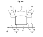
- a swing ring gear, a swing motor, and the like) for swing the upper frame 2 is mounted; left and right side plates 14 and 15 vertically welded on the base plate 13 to face each other and composed of inner and outer vertical plates 14a and 15a, and 14b and 15b to which a boom 5 and a boom cylinder 8 are rotatably fixed by fixing pins 16 and 17, and 18 and 19, respectively; and a joint connection plate 22 having both sides welded on inner sides of the inner vertical plates 14a and 15a and a lower end part welded on the base plate 13, and supporting the left and right side plates 14 and 15 by exhibiting rigidity and flexibility when reaction load from the boom 5 is generated on the fixing pins 16 and 17 due to load generated on the working device during working.
- the joint connection plate 22 is formed in a unit body and is welded on the base plate 13 and the inner vertical plates 14a and 15a.
- At least one bent part 23 is formed on the joint connection part 22.
- a cut part 24 is formed in the center of an upper end part of the joint connection plate 22.
- the both sides of the joint connection plate 22 are welded on the inner sides of the left and right side plates (i.e. the inner sides of the inner vertical plates 14a and 15a) to which the boom 5 and the boom cylinder 8 are rotatably fixed by the fixing pins 16 and 17, and 18 and 19, respectively.
- the lower end parts of the joint connection plate 22 i.e. three sides of the joint connection plate 22
- the fixing position of the joint connection plate 22 welded on the inner vertical plates 14a and 15a can be optimized.
- a safe rigidity and flexibility required for a working device can be secured by increasing the sectional area through the change of the thickness of the joint connection plate 22. Accordingly, it is not required to specially manufacture the corresponding components to order.
- the fatigue strength can be supplemented by increasing the sectional area of the plate-shaped joint connection plate 22 that can be easily supplied and demanded or optimizing the shape of the welded parts.
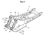
- the joint connection plate 22 is divided into a lower joint connection plate 22a welded on the base plate 13 and the inner vertical plates 14a and 15a, and an upper joint connection plate 22b welded on the inner vertical plates 14a and 15a, as shown in FIGS. 5 , 6 and 7 .
- at least one bent part 23 is formed on at least either of the lower joint connection plate 22a and the upper joint connection plate 22b of the joint connection plate 22.
- the welding position of the joint connection plate 22 on the inner vertical plates 14a and 15a (as shown in FIGS. 6 and 7 ) can be optimized, and the workability in manufacturing the joint connection plate 22 can be improved.
- the upper frame for construction equipment As described above, the upper frame for construction equipment according to the embodiments of the present invention has the following advantages.
- the reliability on the quality of the welded parts can be improved by welding the plate-shaped joint connection plate between the left and right side plates to which fixing pins for rotatably supporting the boom and the boom cylinder are coupled.
- a safe rigidity and flexibility required for the working device can be secured by changing the thickness of the joint connection plate. Accordingly, it is not required to specially manufacture the corresponding components to order, and thus the manufacturing cost of the construction equipment can be reduced.
- the shape of the welding member can be optimized by the plate-shaped joint connection plate that can be easily supplied and demanded, the fatigue strength can be supplemented by increasing the sectional area, and the manufacturing cost and the weight of the construction equipment can be reduced by cutting off the center part that is unnecessary in structural strength.
Landscapes
- Engineering & Computer Science (AREA)
- Structural Engineering (AREA)
- Mining & Mineral Resources (AREA)
- General Engineering & Computer Science (AREA)
- Civil Engineering (AREA)
- Chemical & Material Sciences (AREA)
- Mechanical Engineering (AREA)
- Transportation (AREA)
- Combustion & Propulsion (AREA)
- Architecture (AREA)
- Body Structure For Vehicles (AREA)
- Joining Of Building Structures In Genera (AREA)
- Shovels (AREA)
Applications Claiming Priority (1)
| Application Number | Priority Date | Filing Date | Title |
|---|---|---|---|
| KR1020080017908A KR100979429B1 (ko) | 2008-02-27 | 2008-02-27 | 건설기계의 상부프레임 |
Publications (2)
| Publication Number | Publication Date |
|---|---|
| EP2096213A2 true EP2096213A2 (fr) | 2009-09-02 |
| EP2096213A3 EP2096213A3 (fr) | 2013-06-05 |
Family
ID=40648327
Family Applications (1)
| Application Number | Title | Priority Date | Filing Date |
|---|---|---|---|
| EP09002498.5A Withdrawn EP2096213A3 (fr) | 2008-02-27 | 2009-02-21 | Cadre supérieur pour équipement de construction |
Country Status (5)
| Country | Link |
|---|---|
| US (1) | US7748485B2 (fr) |
| EP (1) | EP2096213A3 (fr) |
| JP (1) | JP2009202869A (fr) |
| KR (1) | KR100979429B1 (fr) |
| CN (1) | CN101519884A (fr) |
Families Citing this family (8)
| Publication number | Priority date | Publication date | Assignee | Title |
|---|---|---|---|---|
| JP4928087B2 (ja) * | 2005-03-14 | 2012-05-09 | ヤンマー株式会社 | 作業車両のフレーム構造 |
| JP5541705B2 (ja) * | 2010-06-11 | 2014-07-09 | 日立建機株式会社 | 建設機械 |
| JP2013221373A (ja) * | 2012-04-19 | 2013-10-28 | Caterpillar Sarl | 建設機械の旋回フレーム |
| JP5786885B2 (ja) * | 2013-04-09 | 2015-09-30 | コベルコ建機株式会社 | 建設機械のスイングブラケット |
| US10711435B2 (en) * | 2016-08-03 | 2020-07-14 | Caterpillar Inc. | Frame assembly for machine |
| WO2019144685A1 (fr) * | 2018-01-26 | 2019-08-01 | Guangxi Liugong Machinery Co., Ltd. | Agencement de levage pour chargeuse montée sur roues |
| JP7201536B2 (ja) * | 2019-05-31 | 2023-01-10 | ヤンマーパワーテクノロジー株式会社 | 建設機械 |
| CN114508148A (zh) * | 2022-02-28 | 2022-05-17 | 徐州徐工矿业机械有限公司 | 一种安装动力装置的框架结构及工程机械 |
Family Cites Families (24)
| Publication number | Priority date | Publication date | Assignee | Title |
|---|---|---|---|---|
| US2458271A (en) * | 1945-07-05 | 1949-01-04 | William M Huston | Rotating base for load handling machines |
| JPS5921192Y2 (ja) * | 1979-10-23 | 1984-06-21 | 株式会社加藤製作所 | パワ−シヨベル用クレ−ンブ−ム取付具 |
| GB2142312B (en) * | 1983-06-29 | 1986-06-18 | Fmc Corp | Modularised pedestal mount crane and method of disassembly |
| AU593719B2 (en) * | 1987-02-04 | 1990-02-15 | Kabushiki Kaisha Komatsu Seisakusho | Front frame of wheeled loader |
| JPH0359223U (fr) * | 1989-10-17 | 1991-06-11 | ||
| US5353940A (en) * | 1993-01-08 | 1994-10-11 | The Manitowoc Company, Inc. | Alignment system for crane works and method of alignment |
| US6003252A (en) * | 1998-08-05 | 1999-12-21 | Davis; Daniel E. | Conversion apparatus and method for use with excavator and crane devices |
| JP2001040706A (ja) * | 1999-08-03 | 2001-02-13 | Komatsu Ltd | 建設機械の旋回台 |
| JP4067070B2 (ja) * | 1999-03-12 | 2008-03-26 | 株式会社小松製作所 | 作業車両の作業機支持構造 |
| JP2001173017A (ja) | 1999-12-17 | 2001-06-26 | Hitachi Constr Mach Co Ltd | 建設機械 |
| JP3634723B2 (ja) | 2000-05-31 | 2005-03-30 | 日立建機株式会社 | 建設機械の旋回フレーム |
| PT1318242E (pt) * | 2001-12-06 | 2007-01-31 | Geith Patents Ltd | Engate para acoplar um acessório a um braço de escavadora e sistema de comando deste engate |
| JP3947009B2 (ja) * | 2002-01-18 | 2007-07-18 | 日立建機株式会社 | 建設機械の旋回フレーム |
| US6648582B2 (en) * | 2002-03-26 | 2003-11-18 | Deere & Company | Boom lock |
| JP3845039B2 (ja) * | 2002-05-20 | 2006-11-15 | ヤンマー株式会社 | 超小旋回作業車 |
| JP4016783B2 (ja) * | 2002-09-30 | 2007-12-05 | コベルコクレーン株式会社 | 移動式作業機械 |
| JP4316950B2 (ja) * | 2003-07-07 | 2009-08-19 | 日立建機株式会社 | 建設機械の旋回フレーム構造 |
| EP1653011B1 (fr) * | 2003-07-07 | 2012-09-26 | Hitachi Construction Machinery Co., Ltd. | Structure a chassis pivotant d'une machine de construction |
| JP4191585B2 (ja) * | 2003-12-15 | 2008-12-03 | 日立建機株式会社 | 建設機械用キャブ |
| JP4226546B2 (ja) * | 2004-03-29 | 2009-02-18 | 株式会社クボタ | 旋回作業機 |
| JP4217687B2 (ja) * | 2005-03-14 | 2009-02-04 | ヤンマー株式会社 | ローダの配管構造 |
| US7481168B2 (en) * | 2005-04-07 | 2009-01-27 | Lawrence Glenn Pike | Off-track railroad track undercutter apparatus |
| KR100689293B1 (ko) * | 2005-07-25 | 2007-03-02 | 볼보 컨스트럭션 이키프먼트 홀딩 스웨덴 에이비 | 건설기계의 운전실 캡을 지지하는 상부프레임 구조 |
| JP2007046374A (ja) * | 2005-08-11 | 2007-02-22 | Sumitomo (Shi) Construction Machinery Manufacturing Co Ltd | 建設機械の旋回フレーム |
-
2008
- 2008-02-27 KR KR1020080017908A patent/KR100979429B1/ko active Active
-
2009
- 2009-02-20 US US12/389,395 patent/US7748485B2/en active Active
- 2009-02-21 EP EP09002498.5A patent/EP2096213A3/fr not_active Withdrawn
- 2009-02-26 JP JP2009043544A patent/JP2009202869A/ja active Pending
- 2009-02-26 CN CN200910118609A patent/CN101519884A/zh active Pending
Also Published As
| Publication number | Publication date |
|---|---|
| KR100979429B1 (ko) | 2010-09-02 |
| US7748485B2 (en) | 2010-07-06 |
| US20090211833A1 (en) | 2009-08-27 |
| EP2096213A3 (fr) | 2013-06-05 |
| CN101519884A (zh) | 2009-09-02 |
| JP2009202869A (ja) | 2009-09-10 |
| KR20090092585A (ko) | 2009-09-01 |
Similar Documents
| Publication | Publication Date | Title |
|---|---|---|
| US7748485B2 (en) | Upper frame for construction equipment | |
| EP1903152A2 (fr) | Structure de cadre supérieur pour le support de la cabine pour machines de construction | |
| US20040161326A1 (en) | Boom structure of construction machine and manufacturing method thereof | |
| EP2065518B1 (fr) | Excavateur avec des réservoirs disposant de portes latérales | |
| US7874390B2 (en) | Working machine | |
| EP2011926A1 (fr) | Cadre supérieur pour excavateur | |
| EP2642032A1 (fr) | Cadre pivotant de machine de construction | |
| EP2078638A2 (fr) | Équipement de construction doté d'un moyen de fixation d'un rétroviseur latéral | |
| JP2009013778A5 (fr) | ||
| JP2007046396A (ja) | 建設機械のキャビン | |
| US7413241B2 (en) | Cab of a working machine | |
| JP5189011B2 (ja) | 建設機械の旋回フレーム | |
| EP2045400A1 (fr) | Appareil pour fixer des conduits hydrauliques pour un excavateur battant sans arrière | |
| JP4283761B2 (ja) | ブラケット構造体 | |
| JP5577015B2 (ja) | 作業機ブーム | |
| JP2011140854A (ja) | 建設機械の旋回フレーム | |
| CN101454512A (zh) | 滑行转向装载机的提升臂 | |
| US9334624B2 (en) | Articulated work machine | |
| EP2466016A1 (fr) | Cadre et son procédé de fabrication | |
| JP4446937B2 (ja) | 建設機械の旋回フレーム | |
| JP2004210500A (ja) | フォークリフトにおけるアウタマストのタイビーム構造 | |
| JP2006045976A (ja) | 建設機械 | |
| JP6101829B1 (ja) | シアプレートの取付構造およびシアプレートの取付方法 | |
| JP2002309607A (ja) | 油圧ショベルの作業機ブーム、アーム | |
| JP5160172B2 (ja) | 作業機部材 |
Legal Events
| Date | Code | Title | Description |
|---|---|---|---|
| PUAI | Public reference made under article 153(3) epc to a published international application that has entered the european phase |
Free format text: ORIGINAL CODE: 0009012 |
|
| AK | Designated contracting states |
Kind code of ref document: A2 Designated state(s): AT BE BG CH CY CZ DE DK EE ES FI FR GB GR HR HU IE IS IT LI LT LU LV MC MK MT NL NO PL PT RO SE SI SK TR |
|
| AX | Request for extension of the european patent |
Extension state: AL BA RS |
|
| PUAL | Search report despatched |
Free format text: ORIGINAL CODE: 0009013 |
|
| AK | Designated contracting states |
Kind code of ref document: A3 Designated state(s): AT BE BG CH CY CZ DE DK EE ES FI FR GB GR HR HU IE IS IT LI LT LU LV MC MK MT NL NO PL PT RO SE SI SK TR |
|
| AX | Request for extension of the european patent |
Extension state: AL BA RS |
|
| RIC1 | Information provided on ipc code assigned before grant |
Ipc: B66C 23/62 20060101ALI20130430BHEP Ipc: E02F 9/08 20060101AFI20130430BHEP Ipc: B62D 25/20 20060101ALI20130430BHEP |
|
| AKY | No designation fees paid | ||
| REG | Reference to a national code |
Ref country code: DE Ref legal event code: R108 |
|
| REG | Reference to a national code |
Ref country code: DE Ref legal event code: R108 Effective date: 20140212 |
|
| STAA | Information on the status of an ep patent application or granted ep patent |
Free format text: STATUS: THE APPLICATION IS DEEMED TO BE WITHDRAWN |
|
| 18D | Application deemed to be withdrawn |
Effective date: 20130606 |