EP2096271A2 - Système et procédé de refroidissement passif de composants de commande de moteur de turbine à gaz - Google Patents
Système et procédé de refroidissement passif de composants de commande de moteur de turbine à gaz Download PDFInfo
- Publication number
- EP2096271A2 EP2096271A2 EP09250455A EP09250455A EP2096271A2 EP 2096271 A2 EP2096271 A2 EP 2096271A2 EP 09250455 A EP09250455 A EP 09250455A EP 09250455 A EP09250455 A EP 09250455A EP 2096271 A2 EP2096271 A2 EP 2096271A2
- Authority
- EP
- European Patent Office
- Prior art keywords
- component
- duct
- cooling
- valve assembly
- valve
- Prior art date
- Legal status (The legal status is an assumption and is not a legal conclusion. Google has not performed a legal analysis and makes no representation as to the accuracy of the status listed.)
- Withdrawn
Links
- 238000001816 cooling Methods 0.000 title claims abstract description 33
- 238000000034 method Methods 0.000 title claims abstract description 12
- 238000004891 communication Methods 0.000 claims abstract description 9
- 239000012530 fluid Substances 0.000 claims abstract description 9
- 230000004044 response Effects 0.000 claims abstract description 7
- 239000007789 gas Substances 0.000 description 27
- 239000000463 material Substances 0.000 description 5
- 239000000446 fuel Substances 0.000 description 4
- 239000000567 combustion gas Substances 0.000 description 3
- 230000006870 function Effects 0.000 description 3
- 230000000712 assembly Effects 0.000 description 2
- 238000000429 assembly Methods 0.000 description 2
- 238000002485 combustion reaction Methods 0.000 description 2
- 230000001276 controlling effect Effects 0.000 description 2
- 230000005484 gravity Effects 0.000 description 2
- 238000009434 installation Methods 0.000 description 2
- 239000011156 metal matrix composite Substances 0.000 description 2
- 239000000203 mixture Substances 0.000 description 2
- 229920005989 resin Polymers 0.000 description 2
- 239000011347 resin Substances 0.000 description 2
- 238000009423 ventilation Methods 0.000 description 2
- 229920000178 Acrylic resin Polymers 0.000 description 1
- 239000004925 Acrylic resin Substances 0.000 description 1
- 229920000271 Kevlar® Polymers 0.000 description 1
- RTAQQCXQSZGOHL-UHFFFAOYSA-N Titanium Chemical compound [Ti] RTAQQCXQSZGOHL-UHFFFAOYSA-N 0.000 description 1
- 229910052782 aluminium Inorganic materials 0.000 description 1
- XAGFODPZIPBFFR-UHFFFAOYSA-N aluminium Chemical compound [Al] XAGFODPZIPBFFR-UHFFFAOYSA-N 0.000 description 1
- 229920003235 aromatic polyamide Polymers 0.000 description 1
- 230000008901 benefit Effects 0.000 description 1
- -1 but not limited to Substances 0.000 description 1
- QHIWVLPBUQWDMQ-UHFFFAOYSA-N butyl prop-2-enoate;methyl 2-methylprop-2-enoate;prop-2-enoic acid Chemical compound OC(=O)C=C.COC(=O)C(C)=C.CCCCOC(=O)C=C QHIWVLPBUQWDMQ-UHFFFAOYSA-N 0.000 description 1
- 239000003575 carbonaceous material Substances 0.000 description 1
- 229910010293 ceramic material Inorganic materials 0.000 description 1
- 230000008859 change Effects 0.000 description 1
- 238000010276 construction Methods 0.000 description 1
- 239000000356 contaminant Substances 0.000 description 1
- 239000000112 cooling gas Substances 0.000 description 1
- 125000004122 cyclic group Chemical group 0.000 description 1
- 230000001419 dependent effect Effects 0.000 description 1
- 238000005516 engineering process Methods 0.000 description 1
- 239000003822 epoxy resin Substances 0.000 description 1
- 239000000284 extract Substances 0.000 description 1
- 239000011152 fibreglass Substances 0.000 description 1
- 239000007770 graphite material Substances 0.000 description 1
- LNEPOXFFQSENCJ-UHFFFAOYSA-N haloperidol Chemical compound C1CC(O)(C=2C=CC(Cl)=CC=2)CCN1CCCC(=O)C1=CC=C(F)C=C1 LNEPOXFFQSENCJ-UHFFFAOYSA-N 0.000 description 1
- 230000001939 inductive effect Effects 0.000 description 1
- 239000004761 kevlar Substances 0.000 description 1
- 229910052751 metal Inorganic materials 0.000 description 1
- 239000002184 metal Substances 0.000 description 1
- 239000007769 metal material Substances 0.000 description 1
- 150000002739 metals Chemical class 0.000 description 1
- 239000004033 plastic Substances 0.000 description 1
- 229920003023 plastic Polymers 0.000 description 1
- 229920000647 polyepoxide Polymers 0.000 description 1
- 229920001225 polyester resin Polymers 0.000 description 1
- 239000004645 polyester resin Substances 0.000 description 1
- 239000002952 polymeric resin Substances 0.000 description 1
- 229920005749 polyurethane resin Polymers 0.000 description 1
- 238000001556 precipitation Methods 0.000 description 1
- 230000002028 premature Effects 0.000 description 1
- 230000001105 regulatory effect Effects 0.000 description 1
- 238000007789 sealing Methods 0.000 description 1
- 230000035939 shock Effects 0.000 description 1
- 229920003002 synthetic resin Polymers 0.000 description 1
- 229920001187 thermosetting polymer Polymers 0.000 description 1
- 239000010936 titanium Substances 0.000 description 1
- 229910052719 titanium Inorganic materials 0.000 description 1
- 230000007704 transition Effects 0.000 description 1
- 238000011144 upstream manufacturing Methods 0.000 description 1
- 229920001567 vinyl ester resin Polymers 0.000 description 1
Images


Classifications
-
- F—MECHANICAL ENGINEERING; LIGHTING; HEATING; WEAPONS; BLASTING
- F01—MACHINES OR ENGINES IN GENERAL; ENGINE PLANTS IN GENERAL; STEAM ENGINES
- F01D—NON-POSITIVE DISPLACEMENT MACHINES OR ENGINES, e.g. STEAM TURBINES
- F01D25/00—Component parts, details, or accessories, not provided for in, or of interest apart from, other groups
- F01D25/08—Cooling; Heating; Heat-insulation
- F01D25/12—Cooling
-
- F—MECHANICAL ENGINEERING; LIGHTING; HEATING; WEAPONS; BLASTING
- F02—COMBUSTION ENGINES; HOT-GAS OR COMBUSTION-PRODUCT ENGINE PLANTS
- F02C—GAS-TURBINE PLANTS; AIR INTAKES FOR JET-PROPULSION PLANTS; CONTROLLING FUEL SUPPLY IN AIR-BREATHING JET-PROPULSION PLANTS
- F02C7/00—Features, components parts, details or accessories, not provided for in, or of interest apart form groups F02C1/00 - F02C6/00; Air intakes for jet-propulsion plants
- F02C7/12—Cooling of plants
-
- H—ELECTRICITY
- H05—ELECTRIC TECHNIQUES NOT OTHERWISE PROVIDED FOR
- H05K—PRINTED CIRCUITS; CASINGS OR CONSTRUCTIONAL DETAILS OF ELECTRIC APPARATUS; MANUFACTURE OF ASSEMBLAGES OF ELECTRICAL COMPONENTS
- H05K7/00—Constructional details common to different types of electric apparatus
- H05K7/20—Modifications to facilitate cooling, ventilating, or heating
- H05K7/20009—Modifications to facilitate cooling, ventilating, or heating using a gaseous coolant in electronic enclosures
- H05K7/20136—Forced ventilation, e.g. by fans
-
- F—MECHANICAL ENGINEERING; LIGHTING; HEATING; WEAPONS; BLASTING
- F05—INDEXING SCHEMES RELATING TO ENGINES OR PUMPS IN VARIOUS SUBCLASSES OF CLASSES F01-F04
- F05D—INDEXING SCHEME FOR ASPECTS RELATING TO NON-POSITIVE-DISPLACEMENT MACHINES OR ENGINES, GAS-TURBINES OR JET-PROPULSION PLANTS
- F05D2270/00—Control
- F05D2270/50—Control logic embodiments
- F05D2270/54—Control logic embodiments by electronic means, e.g. electronic tubes, transistors or IC's within an electronic circuit
-
- Y—GENERAL TAGGING OF NEW TECHNOLOGICAL DEVELOPMENTS; GENERAL TAGGING OF CROSS-SECTIONAL TECHNOLOGIES SPANNING OVER SEVERAL SECTIONS OF THE IPC; TECHNICAL SUBJECTS COVERED BY FORMER USPC CROSS-REFERENCE ART COLLECTIONS [XRACs] AND DIGESTS
- Y02—TECHNOLOGIES OR APPLICATIONS FOR MITIGATION OR ADAPTATION AGAINST CLIMATE CHANGE
- Y02T—CLIMATE CHANGE MITIGATION TECHNOLOGIES RELATED TO TRANSPORTATION
- Y02T50/00—Aeronautics or air transport
- Y02T50/60—Efficient propulsion technologies, e.g. for aircraft
Definitions
- the technology described herein relates generally to gas turbine engines, and more particularly, to a system and method for cooling engine control components for such engines.
- At least one known gas turbine engine assembly includes a fan assembly that is mounted upstream from a core gas turbine engine. During operation, a portion of the airflow discharged from the fan assembly is channeled downstream to the core gas turbine engine wherein the airflow is further compressed. The compressed airflow is then channeled into a combustor, mixed with fuel, and ignited to generate hot combustion gases. The combustion gases are then channeled to a turbine, which extracts energy from the combustion gases for powering the compressor, as well as producing useful work to propel an aircraft in flight. The other portion of the airflow discharged from the fan assembly exits the engine through a fan stream nozzle.
- a variety of different control systems and methods are available for controlling the operation and performance of such aircraft gas turbine engines.
- One type of control system is commonly referred to as a FADEC (Full Authority Digital Engine Control), which is a generic name for a system for electronically controlling an aviation engine.
- a FADEC system includes a central computer system (often referred to as the FADEC) which receives information regarding the position of a throttle lever and other engine control devices operated by a pilot, as well as various information from various sensors fitted to the engine, and controls the engine so as to provide the required levels of performance such as engine thrust, fuel economy, etc.
- Engine control components such as FADEC units often include a number of small wires and electronic components such as computer chips and printed circuit boards.
- gas turbine aircraft engines are subject to a wide range of operating conditions such as high and low altitudes, high and low temperatures, and high and low speed airflows over, around, and through the engine.
- operating conditions such as high and low altitudes, high and low temperatures, and high and low speed airflows over, around, and through the engine.
- the aircraft, its engine(s), and engine control components may experience low speed, low altitude, and high temperature conditions during taxi, takeoff, and landing operations, as well as high speed, high altitude, and low temperature conditions during the cruise portion of the flight.
- Engine control components such as FADEC units are normally housed within the engine cowling or nacelle, where it is protected from precipitation, dirt, debris, and other contaminants which may pass over, around, or through the engine.
- housing the engine control components in close proximity to the engine itself exposes them to potentially high temperatures generated during normal engine operation.
- the engine control components may themselves generate heat which in a confined space tends to expose the unit to higher than desired operating temperatures.
- Ventilation is often provided to direct air which is cooler than the components onto the components to carry heat away and maintain the temperature of the component at a satisfactory operating level.
- cooling needs often vary greatly during the course of a flight or operating session. For example, a much greater degree of cooling may be needed on a hot day during ground operations at engine idle power settings than at high altitude during cruise conditions and high power settings.
- a system for cooling a gas turbine engine control component comprises a control component, at least one duct in fluid communication with the component and the atmosphere, and a valve assembly located with the duct for modulating airflow to the component.
- a method for cooling a gas turbine engine control component comprises the steps of: a) providing a system for cooling the component, the system comprising at least one duct in fluid communication with the component and the atmosphere and a valve assembly located with the duct for modulating airflow to the component; b) exposing the system to a first condition where cooling of the component is required; c) opening the valve assembly in response to the first condition; d) exposing the system to a second condition where cooling of the component is not required; and e) closing the valve assembly in response to the second condition.
- FIG. 1 is a cross-sectional schematic illustration of an exemplary gas turbine engine assembly 10 having a longitudinal axis 30.
- Gas turbine engine assembly 10 includes a fan assembly 14 and a core gas turbine engine 15.
- Core gas turbine engine 15 includes a high pressure compressor 18, a combustor 20, and a high pressure turbine 22.
- gas turbine engine assembly 10 also includes a low pressure turbine 24, and a multi-stage booster compressor 16, and a splitter 17 that substantially circumscribes booster 16.
- Fan assembly 14 includes an array of fan blades extending radially outward from a rotor disk, the forward portion of which is enclosed by a streamlined spinner.
- Gas turbine engine assembly 10 has an intake side 11 and an exhaust side 13.
- Fan assembly 14, booster 16, and turbine 24 are coupled together by a first rotor shaft 28, and compressor 18 and turbine 22 are coupled together by a second rotor shaft 26.
- incoming air 42 flows through fan assembly 14 and a first portion of the airflow is channeled through booster 16 and onward through internal flowpath 50 of core gas turbine engine 15.
- the compressed air that is discharged from booster 16 is channeled through compressor 18 wherein the airflow is further compressed and delivered to combustor 20.
- Hot products of combustion (not shown in Figure 1 ) from combustor 20 are utilized to drive turbines 22 and 24, and turbine 24 is utilized to drive fan assembly 14 and booster 16 by way of shaft 28.
- Air and combustion products flowing through internal flowpath 50 exit the core gas turbine engine 15 at the trailing edge 38 of the core cowl 36 as shown at 44.
- Gas turbine engine assembly 10 is operable at a range of operating conditions between design operating conditions and off-design operating conditions.
- bypass duct 40 extends between a fan casing or shroud, which forms a first or inner surface 31 of the engine nacelle 32 and the core cowl 36 which has a leading edge formed by splitter 17. Air flowing through bypass duct 40 exits the trailing edge 34 of the nacelle 32.
- Nacelle 32 encloses the major portion of the aircraft engine 10 and is secured to the aircraft by appropriate mounting apparatus. In the embodiment shown in Figure 1 , the nacelle 32 is secured to the aircraft wing 12 via mounting pylon 19.
- Gas turbine engine assembly 10 also includes a fan frame assembly 46 to provide structural support for fan assembly 14 and is also utilized to couple fan assembly 14 to core gas turbine engine 15.
- Fan frame assembly 46 includes a plurality of outlet guide vanes that extend substantially radially between a radially outer mounting flange and a radially inner mounting flange and are circumferentially-spaced within bypass duct 40.
- Fan frame assembly 46 may also include a plurality of struts that are coupled between a radially outer mounting flange and a radially inner mounting flange.
- fan frame assembly 46 is fabricated in arcuate segments in which flanges are coupled to outlet guide vanes and struts.
- outlet guide vanes and struts are coupled coaxially within bypass duct 40.
- outlet guide vanes may be coupled downstream from struts within bypass duct 40.
- Fan frame assembly 46 is one of various frame and support assemblies of gas turbine engine assembly 10 that are used to facilitate maintaining an orientation of various components within gas turbine engine assembly 10. More specifically, such frame and support assemblies interconnect stationary components and provide rotor bearing supports. Fan frame assembly 46 is coupled downstream from fan assembly 14 within bypass duct 40 such that outlet guide vanes and struts are circumferentially-spaced around the outlet of fan assembly 14 and extend across the airflow path discharged from fan assembly 14.
- a control component for gas turbine engine 10 such as a Full Authority Digital Engine Control (FADEC) is located within the engine nacelle 32 between the first or inner surface 31 and the second or outer surface 33.
- FADEC Full Authority Digital Engine Control
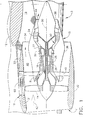
- FIG 2 is a partial cross-sectional elevational view of the forward portion of an exemplary aircraft gas turbine engine, such as depicted in Figure 1 , illustrating installation details of the engine control component 60.
- engine control component 60 is mounted in a compartment 62 within the nacelle 32, which may house other components (not shown) in addition to the engine control component 60.
- Compartment 62 is located between the inner and outer surfaces, 31 and 33, respectively, of the nacelle 32.
- compartment 62 is approximately midway between the leading and trailing edges of the nacelle.
- control component 60 is housed in a casing 61, which at least partially surrounds control component 60 to isolate it from the other elements and space inside of the compartment 62.
- Duct 63 provides fluid communication between an opening 66 on the inner surface 31 and the casing 61, such that air may flow through duct 63 between the casing 61 surrounding control component 60 and the inner surface 31.
- Duct 64 provides fluid communication between an opening 65 on the outer surface 33 and the casing 61, such that air may flow through duct 64 between the casing 61 surrounding control component and the outer surface 33. Accordingly, control component 60 may be exposed to airflow traveling through ducts 63 and 64 from inner surface 31 and/or outer surface 33.
- the elements of the compartment 62, controller casing 61, and ducts 63 and 64 are sized, shaped, adapted, and otherwise configured to suit the characteristics of the particular engine application desired.
- a valve assembly 67 is included to passively modulate airflow through the system and manage the operating temperatures experienced by the engine control component 60.
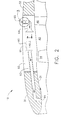
- FIGS 3 and 4 illustrate in greater detail the valve assembly 67 depicted in Figure 2 .
- the valve assembly 67 is in the open position, so that air flows in the direction of the arrows as shown. Accordingly, air flows from opening 65 on the second or outer surface 33 of the nacelle, through duct 64 with the valve assembly 67 in the open position, through casing 61 surrounding control component 60, through duct 63, and out through opening 66 on the first or inner surface 31 of the nacelle.
- This configuration and operating condition would be typical of a low speed, low Mach number, low altitude operating condition such as ground operations or takeoff. Under such conditions, the temperature differences between that of the air available at opening or port 65 and that of the air inside control component 60 are relatively small, and therefore unrestricted air flow through valve assembly 67 is permissible under thermal shock design considerations.
- the valve assembly 67 in the exemplary embodiment shown includes two semicircular valve flaps pivotally mounted with a hinge pin 68.
- the valve assembly 67 is installed such that, in the normal aircraft attitude, gravity acts upon the valve flaps to exert a force on them and bias them downward, to an open position, without any springs, solenoids, or other actuators being necessary.
- the valve flaps include a feature, such as wedges 70, which prevent the valve flaps from reaching a fully open (i.e., vertical as shown) position where the flaps would contact each other. This feature aids in preventing a flutter situation where dynamic forces of air flowing over the valve flaps could cause them to oscillate and potentially cause vibration and/or premature wear of parts of the valve assembly.
- a feature which maintains the valve flaps in a slightly closed (not fully open) position also aids in enabling the valve flaps to respond to a change in airflow direction and pressure, such that they respond and move to a closed condition more readily when the airflow reverses direction.
- the transition point (open/close) is a function of aircraft speed, aircraft angle of attack, and air density. This turning point can be changed by adding to the valve flaps a calibrated weight and changing the position with respect to the turning axis.
- the valve flaps also include a feature such as apertures 71 to permit a measured, minor amount of airflow through the system when the valve is in a closed position.
- valve stops 69 against which the valve flaps rest when in a fully closed condition, to limit their travel and prevent going over-center.
- the valve stop or stops 69 may also take the form of a complete annular ring, or ring segments, since with the presence of apertures 71 it is not necessary for any particular amount of clearance to be provided at the edges of the valve flaps for the passage of air in the closed position.
- a bumper or seal 72 may be provided in association with the valve stop or stops 69 to reduce vibration and reduce or prevent air leaks when the valve is closed.
- the bumper or seal 72 is also discontinuous, while for a valve stop in the form of a continuous annular ring the bumper or seal 72 may be either continuous (forming an annular ring) or discontinuous (forming one or more annular segments).
- the degree of influence the bumper or seal 72 has on air passage, i.e., the degree of sealing capability, is dependent upon the degree of continuity of the seal 72. Where the bumper or seal 72 is discontinuous, it tends to function more as a bumper than as a seal.
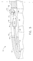
- Figures 5 , 6, and 7 correspond to Figures 2 , 3, and 4 , and illustrate comparable views of the same components but with Figures 5 , 6, and 7 illustrating the reversed airflow (as indicated by the arrows) and the valve assembly 67 in a closed condition.
- the valve flaps are against the valve stops 69, and the apertures 71 may be sized and adapted to provide a measured amount of airflow through the substantially closed valve assembly to maintain the engine control component 60 at a desired temperature during valve-closed operation.
- Apertures 71 are optional, and if desired could be omitted if a total obstruction to airflow through the system were desired.
- This configuration and operating condition would be typical of a high speed, high Mach number, high altitude operating condition such as cruise or other high speed flight. Under such conditions, the temperature of the air available to flow through the system is comparatively cool, therefore the amount of cooling air required to keep the control component 60 under normal operating temperature is relatively small.
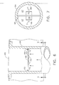
- Figure 8 illustrates a variation of the valve configuration described above.
- the valve flaps are sized so as to be smaller in diameter when fully closed than the diameter of the duct. This creates a gap 72, which functions similarly to the apertures 71 described above in terms of permitting a measured, comparatively small amount of airflow through and past the valve assembly 67.
- the valve stop or stops 69 preferably are discrete small elements or ring segments and do not form a complete annular ring, since with the presence of gap 72 it is necessary for clearance to be provided at the edges of the valve flaps for the passage of air in the closed position.
- valve assembly 67 in either duct 63 or duct 64 may be chosen, depending upon the characteristics of the particular application. However, orienting the valve assembly 67 as to take advantage of gravity as the biasing force to bias the valve to an open position eliminates the need for springs, solenoids, or other actuators being necessary so as to maintain a simple, reliable, lightweight design which operates automatically or passively in response to operating conditions without manual or system intervention.
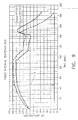
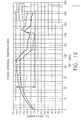
- FIGS 9 and 10 are graphical illustrations of internal operating temperatures experienced by a FADEC unit for one particular engine application during the course of an operating session.
- the maximum temperature difference, denoted by the reference identifier T in Figures 9 and 10 is approximately 60 degrees Fahrenheit in Figure 9 when operating with a conventional fixed ducting system where the airflow is not regulated and approximately 25 degrees Fahrenheit in Figure 10 when a system as described herein is employed.
- the ducts and casing may be a fiberglass material, a graphite material, a carbon material, a ceramic material, an aromatic polyamid material such as KEVLAR, a thin metallic material such as, but not limited to, titanium, aluminum, and/or a Metal Matrix Composite (MMC) material, and/or mixtures thereof.
- Any suitable thermosetting polymeric resin can be used in forming the ducts and casing, for example, vinyl ester resin, polyester resins, acrylic resins, epoxy resins, polyurethane resins, bismalimide resin, and mixtures thereof. Materials should be selected based on the temperature, vibration, and flexure considerations to which the components may be exposed.
- valve assembly may be constructed from a wide variety of suitable materials, including metals and plastics, particularly those of relatively light weight.
Landscapes
- Engineering & Computer Science (AREA)
- Microelectronics & Electronic Packaging (AREA)
- Mechanical Engineering (AREA)
- General Engineering & Computer Science (AREA)
- Chemical & Material Sciences (AREA)
- Combustion & Propulsion (AREA)
- Physics & Mathematics (AREA)
- Thermal Sciences (AREA)
- Turbine Rotor Nozzle Sealing (AREA)
- Structures Of Non-Positive Displacement Pumps (AREA)
Applications Claiming Priority (1)
| Application Number | Priority Date | Filing Date | Title |
|---|---|---|---|
| US12/040,126 US20090175718A1 (en) | 2007-12-31 | 2008-02-29 | System and method for passive cooling of gas turbine engine control components |
Publications (1)
| Publication Number | Publication Date |
|---|---|
| EP2096271A2 true EP2096271A2 (fr) | 2009-09-02 |
Family
ID=40581440
Family Applications (1)
| Application Number | Title | Priority Date | Filing Date |
|---|---|---|---|
| EP09250455A Withdrawn EP2096271A2 (fr) | 2008-02-29 | 2009-02-20 | Système et procédé de refroidissement passif de composants de commande de moteur de turbine à gaz |
Country Status (4)
| Country | Link |
|---|---|
| US (1) | US20090175718A1 (fr) |
| EP (1) | EP2096271A2 (fr) |
| JP (1) | JP2009209932A (fr) |
| CA (1) | CA2655842A1 (fr) |
Cited By (3)
| Publication number | Priority date | Publication date | Assignee | Title |
|---|---|---|---|---|
| FR2995497A1 (fr) * | 2012-09-10 | 2014-03-14 | Airbus Operations Sas | Systeme de refroidissement d'au moins un dispositif electronique d'un turbomoteur d'aeronef. |
| US9261112B2 (en) | 2012-04-24 | 2016-02-16 | General Electric Company | Dampers for fan spinners of aircraft engines |
| CN114856822A (zh) * | 2018-01-18 | 2022-08-05 | 通用电气公司 | 热保护的热塑性管道和组件 |
Families Citing this family (38)
| Publication number | Priority date | Publication date | Assignee | Title |
|---|---|---|---|---|
| FR2938293B1 (fr) * | 2008-11-12 | 2015-08-21 | Snecma | Dispositif de regulation du debit d'air alimentant une cavite de ventillation de turbine d'une section de turbine de turbomachine |
| US8991191B2 (en) * | 2009-11-24 | 2015-03-31 | General Electric Company | Thermally actuated passive gas turbine engine compartment venting |
| US9284887B2 (en) | 2009-12-31 | 2016-03-15 | Rolls-Royce North American Technologies, Inc. | Gas turbine engine and frame |
| FR2982588B1 (fr) * | 2011-11-10 | 2013-11-22 | Aircelle Sa | Panneau composite a ecope de prelevement integree |
| GB2497809B (en) | 2011-12-22 | 2014-03-12 | Rolls Royce Plc | Method of servicing a gas turbine engine |
| GB2498006B (en) | 2011-12-22 | 2014-07-09 | Rolls Royce Plc | Gas turbine engine systems |
| US9478896B2 (en) | 2011-12-22 | 2016-10-25 | Rolls-Royce Plc | Electrical connectors |
| FR2988978B1 (fr) * | 2012-03-28 | 2014-06-27 | Safran | Support boitier fadec en materiau composite |
| BR112014026637A2 (pt) * | 2012-04-27 | 2017-06-27 | Gen Electric | rotor de alta pressão de motor de turbina a gás. |
| WO2014022344A1 (fr) * | 2012-07-31 | 2014-02-06 | General Electric Company | Capot central en cmc et procédé de fabrication |
| US9429072B2 (en) | 2013-05-22 | 2016-08-30 | General Electric Company | Return fluid air cooler system for turbine cooling with optional power extraction |
| US9422063B2 (en) | 2013-05-31 | 2016-08-23 | General Electric Company | Cooled cooling air system for a gas turbine |
| US9617917B2 (en) | 2013-07-31 | 2017-04-11 | General Electric Company | Flow control assembly and methods of assembling the same |
| FR3009340B1 (fr) * | 2013-08-01 | 2018-03-09 | Safran Aircraft Engines | Ventilation d'un equipement de turbomachine |
| EP3009607A1 (fr) * | 2014-10-13 | 2016-04-20 | United Technologies Corporation | Aube fixe-variable avec enrobage dans l'interstice |
| US20170184026A1 (en) * | 2015-12-28 | 2017-06-29 | General Electric Company | System and method of soakback mitigation through passive cooling |
| US10927763B2 (en) * | 2016-04-05 | 2021-02-23 | Raytheon Technologies Corporation | Conditioned low pressure compressor compartment for gas turbine engine |
| US20180149086A1 (en) * | 2016-11-29 | 2018-05-31 | General Electric Company | Turbine engine and method of cooling thereof |
| US10557416B2 (en) * | 2017-06-12 | 2020-02-11 | United Technologies Corporation | Flow modulating airfoil apparatus |
| FR3072724A1 (fr) * | 2017-10-24 | 2019-04-26 | Airbus Operations (S.A.S.) | Turbomachine d'aeronef comprenant un compartiment muni d'un ensemble de ventilation |
| US10954814B2 (en) * | 2018-09-26 | 2021-03-23 | Honeywell International Inc. | System with thin walled cooling plate for an electronic enclosure |
| GB2587669A (en) * | 2019-10-02 | 2021-04-07 | Advanced Mobility Res And Development Ltd | Systems and methods for aircraft |
| GB202001821D0 (en) * | 2020-02-11 | 2020-03-25 | Rolls Royce Plc | Gas turbine engine cooling system |
| US11047306B1 (en) | 2020-02-25 | 2021-06-29 | General Electric Company | Gas turbine engine reverse bleed for coking abatement |
| US12031484B2 (en) | 2021-01-28 | 2024-07-09 | General Electric Company | Gas turbine engine cooling system control |
| CZ309432B6 (cs) * | 2022-01-20 | 2023-01-04 | První brněnská strojírna Velká Bíteš, a.s | Chladící zařízení pro výkonové prvky řídicí jednotky turbínového motoru |
| US12392290B2 (en) | 2022-11-01 | 2025-08-19 | General Electric Company | Gas turbine engine |
| US12503980B2 (en) | 2022-11-01 | 2025-12-23 | General Electric Company | Gas turbine engine |
| US12535033B2 (en) | 2022-11-01 | 2026-01-27 | General Electric Company | Gas turbine engine |
| US12196131B2 (en) | 2022-11-01 | 2025-01-14 | General Electric Company | Gas turbine engine |
| US12410753B2 (en) | 2022-11-01 | 2025-09-09 | General Electric Company | Gas turbine engine |
| US12428992B2 (en) | 2022-11-01 | 2025-09-30 | General Electric Company | Gas turbine engine |
| US11834993B1 (en) * | 2023-03-29 | 2023-12-05 | Pratt & Whitney Canada Corp. | Engine exhaust reverse flow prevention |
| US12221927B2 (en) | 2023-04-21 | 2025-02-11 | Pratt & Whitney Canada Corp. | Flammable fluid reservoir |
| US12044173B1 (en) | 2023-04-28 | 2024-07-23 | Pratt & Whitney Canada Corp. | Engine exhaust reverse flow prevention |
| US12326092B2 (en) | 2023-05-16 | 2025-06-10 | Pratt & Whitney Canada Corp. | Engine exhaust reverse flow prevention |
| US12203415B2 (en) | 2023-06-20 | 2025-01-21 | Pratt & Whitney Canada Corp. | Engine exhaust reverse flow prevention |
| US12540551B1 (en) | 2025-07-01 | 2026-02-03 | General Electric Company | Gas turbine engines including splittered airfoils |
Family Cites Families (14)
| Publication number | Priority date | Publication date | Assignee | Title |
|---|---|---|---|---|
| US3023771A (en) * | 1960-03-08 | 1962-03-06 | John K Hinds | Check valve |
| US4006775A (en) * | 1974-03-07 | 1977-02-08 | Avrea Walter C | Automatic positive anti-aeration system for engine cooling system |
| US4457670A (en) * | 1978-09-28 | 1984-07-03 | General Electric Company | Methods and apparatus for pumping compressible dynamoelectric machine lubricant material |
| US4351150A (en) * | 1980-02-25 | 1982-09-28 | General Electric Company | Auxiliary air system for gas turbine engine |
| US4504030A (en) * | 1982-12-06 | 1985-03-12 | United Technologies Corporation | Cooling means |
| JPS59208800A (ja) * | 1983-05-12 | 1984-11-27 | 株式会社日立製作所 | 自動車用電子装置 |
| JPH0712671Y2 (ja) * | 1987-04-29 | 1995-03-29 | 本田技研工業株式会社 | 内燃機関の排気装置 |
| US5400215A (en) * | 1993-01-27 | 1995-03-21 | Chung; Pao-Lang | Support structure for a vehicle-data recorder having a bearing plate with casters |
| US5301709A (en) * | 1993-04-01 | 1994-04-12 | Gulf Valve Company | Check valve and method of assembly |
| EP0655881A1 (fr) * | 1993-11-26 | 1995-05-31 | Siemens Aktiengesellschaft | Boîtier |
| GB2302994B (en) * | 1995-07-01 | 1999-06-09 | British Aerospace | Thermal and shock resistant data recorder assembly |
| US6851255B2 (en) * | 2002-12-18 | 2005-02-08 | Pratt & Whitney Canada Corp. | Normally open reverse flow flapper valve |
| US7448219B2 (en) * | 2004-06-21 | 2008-11-11 | Boeing Co | Hingeless flapper valve for flow control |
| US7493770B2 (en) * | 2004-08-09 | 2009-02-24 | General Electric Company | Methods and apparatus for regulating airflow supply systems |
-
2008
- 2008-02-29 US US12/040,126 patent/US20090175718A1/en not_active Abandoned
-
2009
- 2009-02-20 EP EP09250455A patent/EP2096271A2/fr not_active Withdrawn
- 2009-02-25 JP JP2009041707A patent/JP2009209932A/ja active Pending
- 2009-02-26 CA CA002655842A patent/CA2655842A1/fr not_active Abandoned
Cited By (3)
| Publication number | Priority date | Publication date | Assignee | Title |
|---|---|---|---|---|
| US9261112B2 (en) | 2012-04-24 | 2016-02-16 | General Electric Company | Dampers for fan spinners of aircraft engines |
| FR2995497A1 (fr) * | 2012-09-10 | 2014-03-14 | Airbus Operations Sas | Systeme de refroidissement d'au moins un dispositif electronique d'un turbomoteur d'aeronef. |
| CN114856822A (zh) * | 2018-01-18 | 2022-08-05 | 通用电气公司 | 热保护的热塑性管道和组件 |
Also Published As
| Publication number | Publication date |
|---|---|
| JP2009209932A (ja) | 2009-09-17 |
| CA2655842A1 (fr) | 2009-08-29 |
| US20090175718A1 (en) | 2009-07-09 |
Similar Documents
| Publication | Publication Date | Title |
|---|---|---|
| EP2096271A2 (fr) | Système et procédé de refroidissement passif de composants de commande de moteur de turbine à gaz | |
| US11788470B2 (en) | Gas turbine engine thermal management | |
| CN107893701B (zh) | 用于整流罩下分流冷却的方法和设备 | |
| CA2768929C (fr) | Derivation du prerefroidisseur d'alimentation d'un systeme de conditionnement d'air | |
| US5505587A (en) | RAM air turbine generating apparatus | |
| CN106986035B (zh) | 用于飞行器的后发动机 | |
| US20080010969A1 (en) | Gas turbine engine and method of operating same | |
| EP3219957B1 (fr) | Système de gestion thermique de dégivrage d'aéronef avec restricteur de flux en fonction de la température | |
| EP3608228B1 (fr) | Ensemble de ventilateur électrique pré-refroidisseur | |
| EP3290659B1 (fr) | Air de refroidissement supplémentaire pour composants et surfaces d'échappement de turbine | |
| US20170191420A1 (en) | Method and system for equipment compartment cooling | |
| US10927963B2 (en) | Direct-acting valve | |
| CN116122970A (zh) | 燃气涡轮发动机降噪 | |
| US9790794B2 (en) | Propeller comprising a moveable dynamic scoop | |
| US11215295B2 (en) | Controller assembly | |
| US20200088097A1 (en) | Ported shroud system for turboprop inlets | |
| US10556702B2 (en) | Aircraft having an airflow duct | |
| US11807379B2 (en) | Turbofan engine, nacelle thereof, and associated method of operation | |
| US20110138814A1 (en) | Aircraft Engine Airflow Modulation Apparatus and Method for Engine Bay Cooling and Cycle Flow Matching | |
| CN118532280A (zh) | 减小边界层引起的畸变的具有开式风扇的发动机 | |
| US12312997B2 (en) | Turbine engine having a bleed system | |
| US12276229B2 (en) | Method of operating a turbine engine having a bleed system | |
| JPS60228731A (ja) | 空気制御装置 | |
| Decher | Bypass and Other Engines | |
| Rowe | The design and development of the CJ610 turbojet and the CF700 turbofan engines for use in business jet aircraft |
Legal Events
| Date | Code | Title | Description |
|---|---|---|---|
| PUAI | Public reference made under article 153(3) epc to a published international application that has entered the european phase |
Free format text: ORIGINAL CODE: 0009012 |
|
| AK | Designated contracting states |
Kind code of ref document: A2 Designated state(s): AT BE BG CH CY CZ DE DK EE ES FI FR GB GR HR HU IE IS IT LI LT LU LV MC MK MT NL NO PL PT RO SE SI SK TR |
|
| AX | Request for extension of the european patent |
Extension state: AL BA RS |
|
| STAA | Information on the status of an ep patent application or granted ep patent |
Free format text: STATUS: THE APPLICATION IS DEEMED TO BE WITHDRAWN |
|
| 18D | Application deemed to be withdrawn |
Effective date: 20130903 |