EP2096321B1 - Compresseur - Google Patents
Compresseur Download PDFInfo
- Publication number
- EP2096321B1 EP2096321B1 EP07851000.5A EP07851000A EP2096321B1 EP 2096321 B1 EP2096321 B1 EP 2096321B1 EP 07851000 A EP07851000 A EP 07851000A EP 2096321 B1 EP2096321 B1 EP 2096321B1
- Authority
- EP
- European Patent Office
- Prior art keywords
- casing
- compressor
- struts
- rotor shaft
- outer casing
- Prior art date
- Legal status (The legal status is an assumption and is not a legal conclusion. Google has not performed a legal analysis and makes no representation as to the accuracy of the status listed.)
- Revoked
Links
- 239000012530 fluid Substances 0.000 claims description 11
- 230000002093 peripheral effect Effects 0.000 claims description 6
- 238000011144 upstream manufacturing Methods 0.000 claims description 6
- 239000007789 gas Substances 0.000 description 13
- 239000000567 combustion gas Substances 0.000 description 7
- 238000002485 combustion reaction Methods 0.000 description 3
- 230000006835 compression Effects 0.000 description 2
- 238000007906 compression Methods 0.000 description 2
- 230000007423 decrease Effects 0.000 description 2
- 239000000446 fuel Substances 0.000 description 2
- 238000001816 cooling Methods 0.000 description 1
- 230000000694 effects Effects 0.000 description 1
- 238000004299 exfoliation Methods 0.000 description 1
- 239000002737 fuel gas Substances 0.000 description 1
- 238000009434 installation Methods 0.000 description 1
- 238000000926 separation method Methods 0.000 description 1
- 230000003068 static effect Effects 0.000 description 1
Images




Classifications
-
- F—MECHANICAL ENGINEERING; LIGHTING; HEATING; WEAPONS; BLASTING
- F04—POSITIVE - DISPLACEMENT MACHINES FOR LIQUIDS; PUMPS FOR LIQUIDS OR ELASTIC FLUIDS
- F04D—NON-POSITIVE-DISPLACEMENT PUMPS
- F04D29/00—Details, component parts, or accessories
- F04D29/40—Casings; Connections of working fluid
- F04D29/52—Casings; Connections of working fluid for axial pumps
- F04D29/54—Fluid-guiding means, e.g. diffusers
-
- F—MECHANICAL ENGINEERING; LIGHTING; HEATING; WEAPONS; BLASTING
- F04—POSITIVE - DISPLACEMENT MACHINES FOR LIQUIDS; PUMPS FOR LIQUIDS OR ELASTIC FLUIDS
- F04D—NON-POSITIVE-DISPLACEMENT PUMPS
- F04D29/00—Details, component parts, or accessories
- F04D29/40—Casings; Connections of working fluid
- F04D29/52—Casings; Connections of working fluid for axial pumps
- F04D29/522—Casings; Connections of working fluid for axial pumps especially adapted for elastic fluid pumps
-
- F—MECHANICAL ENGINEERING; LIGHTING; HEATING; WEAPONS; BLASTING
- F02—COMBUSTION ENGINES; HOT-GAS OR COMBUSTION-PRODUCT ENGINE PLANTS
- F02C—GAS-TURBINE PLANTS; AIR INTAKES FOR JET-PROPULSION PLANTS; CONTROLLING FUEL SUPPLY IN AIR-BREATHING JET-PROPULSION PLANTS
- F02C7/00—Features, components parts, details or accessories, not provided for in, or of interest apart form groups F02C1/00 - F02C6/00; Air intakes for jet-propulsion plants
- F02C7/04—Air intakes for gas-turbine plants or jet-propulsion plants
-
- F—MECHANICAL ENGINEERING; LIGHTING; HEATING; WEAPONS; BLASTING
- F04—POSITIVE - DISPLACEMENT MACHINES FOR LIQUIDS; PUMPS FOR LIQUIDS OR ELASTIC FLUIDS
- F04D—NON-POSITIVE-DISPLACEMENT PUMPS
- F04D29/00—Details, component parts, or accessories
- F04D29/40—Casings; Connections of working fluid
- F04D29/52—Casings; Connections of working fluid for axial pumps
- F04D29/54—Fluid-guiding means, e.g. diffusers
- F04D29/541—Specially adapted for elastic fluid pumps
- F04D29/542—Bladed diffusers
- F04D29/544—Blade shapes
-
- F—MECHANICAL ENGINEERING; LIGHTING; HEATING; WEAPONS; BLASTING
- F04—POSITIVE - DISPLACEMENT MACHINES FOR LIQUIDS; PUMPS FOR LIQUIDS OR ELASTIC FLUIDS
- F04D—NON-POSITIVE-DISPLACEMENT PUMPS
- F04D29/00—Details, component parts, or accessories
- F04D29/66—Combating cavitation, whirls, noise, vibration or the like; Balancing
- F04D29/661—Combating cavitation, whirls, noise, vibration or the like; Balancing especially adapted for elastic fluid pumps
- F04D29/663—Sound attenuation
-
- F—MECHANICAL ENGINEERING; LIGHTING; HEATING; WEAPONS; BLASTING
- F04—POSITIVE - DISPLACEMENT MACHINES FOR LIQUIDS; PUMPS FOR LIQUIDS OR ELASTIC FLUIDS
- F04D—NON-POSITIVE-DISPLACEMENT PUMPS
- F04D29/00—Details, component parts, or accessories
- F04D29/66—Combating cavitation, whirls, noise, vibration or the like; Balancing
- F04D29/661—Combating cavitation, whirls, noise, vibration or the like; Balancing especially adapted for elastic fluid pumps
- F04D29/666—Combating cavitation, whirls, noise, vibration or the like; Balancing especially adapted for elastic fluid pumps by means of rotor construction or layout, e.g. unequal distribution of blades or vanes
-
- F—MECHANICAL ENGINEERING; LIGHTING; HEATING; WEAPONS; BLASTING
- F04—POSITIVE - DISPLACEMENT MACHINES FOR LIQUIDS; PUMPS FOR LIQUIDS OR ELASTIC FLUIDS
- F04D—NON-POSITIVE-DISPLACEMENT PUMPS
- F04D29/00—Details, component parts, or accessories
- F04D29/66—Combating cavitation, whirls, noise, vibration or the like; Balancing
- F04D29/661—Combating cavitation, whirls, noise, vibration or the like; Balancing especially adapted for elastic fluid pumps
- F04D29/667—Combating cavitation, whirls, noise, vibration or the like; Balancing especially adapted for elastic fluid pumps by influencing the flow pattern, e.g. suppression of turbulence
Definitions
- the present invention relates to a compressor that compresses air.
- combustion gas for rotating a turbine in a gas turbine is generated by a combustor combusting fuel gas with compressed air that is compressed with a compressor.
- An intake duct that draws in air from the open air is installed at the inlet of the compressor that generates this compressed air.
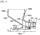
- an intake duct 100 is formed to have a single suction structure with the upper side being opened so as to draw in the open air along with having a ring shape at the periphery of a rotor shaft 5 at the distal end of the rotor shaft 5 at which a rotor blade 12 of a compressor 101 is installed.
- an intake casing 100a on the side of the rotor shaft 5 connects with an inner casing 101 a that covers the periphery of the rotor shaft 5, and an outer side intake casing 100b connects with an outer casing 101b that is disposed on the outer periphery of the inner casing 101 a.
- an annular space that is enclosed by the inner casing 101a and the outer casing 101b serves as an air flow path 101c, and a stator blade 11 and the rotor blade 12 are alternately arranged. Then, air that has been drawn in through the intake duct 100 is compressed by rotation of the rotor blade 12 via the rotor shaft 5.
- a bell mouth shape is formed in which the distal end of the intake casing 100b and the outer casing 101b are curved in the outer peripheral direction, and this curved portion 101d is swelled toward the inner wall of the intake casing 100a.
- the intake casing 100b is connected to the distal end of the curved portion 101d of the outer casing 101b.
- the intake duct 100 is constituted by the intake casings 100a, 100b, the inner casing 101a, and the outer casing 101b, but the inner casing 101a is constituted by being extended further toward the distal end of the rotor shaft 5 than the outer casing 101b.
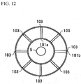
- a plurality of struts 103 are provided in a radial pattern centered on the rotor shaft 5. Conventionally, these plurality of struts 103 have always been disposed at an equal spacings with respect to the circumferential direction of the rotor shaft 5 as shown in FIG. 12 (refer to JP H07-17994 , page 4 and Figs. 4 , 5 ).
- WO 2005 119028A discloses a gas turbine compression system that forms part of a gas turbine engine.
- a plurality of struts are provided within the flow channel between the respective stages of the compressor which are not only structural struts connecting the inner and outer components of the casing but simultaneously have an aerodynamic function in that they are provided with a cambered airfoil shape for turning the gas flow in a particular direction between the stator and rotor blades.
- JP S57-176400A on which the preamble portion of the new claim 1 is based, discloses a gas turbine which has a suction part of a compressor section formed as an integral structure of inner and outer portions of a casing defining the air inlet without any supporting struts.
- the suction part further has an annular mouth ring curved to a bell shape for taking in air.
- a slit is provided on the mouth ring to provide a communication between an upstream area of an air inlet with high static pressure and a downstream curved part of the suction part.
- the intake duct 100 is constituted as shown in FIG 11 , it is constituted as the single suction structure that draws in open air from a direction perpendicular to the rotor shaft 5. Accordingly, since the air that is distributed in the circumferential direction of the rotor shaft 5 in the annular space 102 does not have a balanced flow rate with respect to the flow path area in the circumferential direction, a drift in the circumferential direction exists in the flow of that air.
- forming the curved portion 101d near the connection portion between the intake casing 100b and the outer casing 101b into a smooth bell mouth shape accelerates the flow of air that flows along the wall surface formed by the intake casing 100b and the outer casing 101b.
- the flow that flows into the struts 103 has a three-dimensional drift that is distributed in the span direction as well.
- the profile loss increases at locations where the flow of air becomes fast. This is because the profile loss is proportional to the square of the velocity.
- the present invention was achieved in view of the above circumstances, and has as its object to provide a compressor having a high degree of freedom of blade design and having a high compression efficiency.
- a compressor of the present invention comprises the features of claim 1.
- n struts may be arranged in the circumferential direction of the rotor shaft (n being an integer of 2 or more) and the difference between the maximum value and the minimum value of the angle expressing the spacings of the adjacent struts when centered on the rotor shaft may be at least 120 degrees/n.
- the intake duct of the compressor of the present invention may be further provided with a first casing that is connected to the inner casing at the entrance end of the fluid flow path, and a second casing that is connected to the outer casing at the entrance end of the fluid flow path; in which a curved portion that curves so as to project toward the first casing may be formed at the connection portion of the outer casing with the second casing.
- the curved portion may have: a flat portion that is adjacent to the second casing and consists of a surface that is approximately parallel with the peripheral surface of the rotor shaft; and a curved surface that smoothly curves inward in the radial direction of the rotor shaft from the distal end of the flat portion, in which a cross-section of the curved portion may form an approximate U-shape that projects toward the first casing.
- connection portions of the struts with the outer casing may be positioned further to the downstream in the axial direction of the rotor shaft than the distal end of the curved portion.
- the length in the axial direction of a portion adjacent to an open air suction port that is formed at the distal end of the first casing and the second casing may be longer than the length in the axial direction of another portion that is positioned further from the suction port than the portion.
- the distal end of a portion that is adjacent to an open air suction port that is formed at the distal end of the first casing and the second casing may project further toward the first casing than the distal end of another portion that is positioned further from the suction port than the portion.
- connection portions of the struts with the outer casing may be positioned further downstream in the axial direction of the rotor shaft than the connection portions of the struts with the inner casing.
- the distance in the axial direction of the connection portion between the struts with the outer casing and the distance in the axial direction of the connection portion between the struts with the inner casing may be longer the closer the struts are to the suction port.
- the spacings between the struts in the circumferential direction of the rotor shaft are unequal. Accordingly, it is possible to reduce the harmonic component that occurs in the case of the struts being arranged at equal spacings as before. That is, within the compressor, it is possible to distribute the exciting force at each frequency in a frequency distribution of fluids that flow to the downstream of the struts. By doing so, since it is possible to reduce the harmonic component that has occurred in a conventional shape, it is possible to increase the degree of freedom of blade design in the compressor.
- the flat portion that consists of a surface that is approximately parallel with the peripheral surface of the rotor shaft at the curved portion in the connection portion of the second casing and the outer casing, it is possible to stop the flow of fluid that flows from the periphery of the inner wall of the second casing. Thereby, it is possible to flow the fluid in the circumferential direction of the rotor shaft along this flat portion, and it is possible to make the flow of the fluid that flows from the distal end of the curved portion nearly the same condition in the circumferential direction of the rotor shaft. Thereby it is possible to reduce drifts in flow supplied to the compressor and possible to suppress a drop in efficiency of the compressor.
- connection position of the struts with the outer casing becoming a removed position with respect to the connection portion of the second casing and the outer casing, it is possible to make the flow of fluid that flows into periphery in the radial direction of the rotor shaft with respect to the struts more uniform.
- it is possible to reduce the pressure loss at the periphery with respect to the radial direction of the rotor shaft in the struts it is possible to suppress a drop in efficiency of the compressor.
- FIG. 1 is an outline sectional view that shows the constitution of the gas turbine.
- the gas turbine is provided with a compressor 1 that compresses air, a combustor 2 that performs a combustion operation with air that is compressed by the compressor 1 and a fuel being supplied, and a turbine 3 that is rotationally driven by combustion gas from the combustor 2.
- the compressor 1 and the turbine 3 are respectively covered by the cabins 40a, 40b, and a plurality of the combustors 2 are provided at equal spacings on the periphery of a rotor shaft 5 that makes the compressor 1 and the turbine 3 a single axis.
- an intake duct 6 of a single suction structure that is provided with a suction port 7 for drawing in air, to be supplied to the compressor 1 from the open air, in a direction perpendicular to the rotor shaft 5 (the radial direction of the rotor shaft 5) is arranged in the upstream of the compressor 1.
- the cabin 40a is constituted by an inner casing 4a and an outer casing 4b that are respectively formed on the inner side and the outer side with respect to the radial direction of the rotor shaft 5.
- this intake duct 6 is constituted by an intake casing (first casing) 6a and an intake casing (second casing) 6b that are respectively connected to the inner casing 4a and an outer casing 4b.
- the intake duct 6 has a structure that is provided with an annular space 10 by the intake casings 6a, 6b of a concentric annular shape, and the open air is supplied from the suction port 7 that is open in the radial direction of the rotor shaft 5 in the space that is formed by the intake casings 6a, 6b.
- the suction port 7 is provided at the upside, but the suction port 7 is not limited to the upside, but may be open in any radial direction of the rotor shaft 5.
- the cabin 40a has a double pipe structure by the inner casing 4a and the outer casing 4b of concentric cylinder shape, and a compressed air flow path 13 is constituted in the space between the inner casing 4a and the outer casing 4b.
- a strut 8 for supporting the inner casing 4a and the outer casing 4b is provided at an inlet side of the compressor 1. That is, the strut 8 is provided at a stage prior to a stator blade 11 of the first stage that is an IGV (inlet guide vane) of the compressor 1.
- the first stage stator blade 11 that serves as the IGV is a movable blade that can be opened and closed, and it is possible to set a flow rate that is supplied to the compressor 1 from the intake duct 6 with this first stage stator blade 11.
- stator blade 11 that is fixed to the outer casing 4b and the rotor blade 12 that is fixed to the rotor shaft 5 are alternately arranged in the compressed air flow path 13, and air from open air that is drawn in by the intake duct 6 is supplied.
- a stator blade 31 that is fixed to the turbine cabin 40b and a rotor blade 32 that is fixed to the rotor shaft 5 are alternately arranged in a turbine flow path 33, and combustion gas that is produced by the combustor 2 is supplied.
- the air that is compressed by the compressor 1 is supplied to the combustor 2. Then, the compressed air that is supplied to the combustor 2 is used in the combustion of the fuel that is supplied to the combustor 2. A portion of the compressed air is used for cooling of the stator blade 31 that is fixed to the turbine cabin 40b and the rotor blade 32 that is fixed to the rotor shaft 5, which are exposed to high temperature by the combustion gas from the combustor 2.
- the combustion gas that is generated by the combustion operation in the combustor 2 is supplied to the turbine 3, and the turbine 3 is rotationally driven by the combustion gas alternately passing the rotor blade 32 and the stator blade 31.
- the compressor 1 is thus rotationally driven by the rotational driving of the turbine 3 being transmitted to the compressor 1 via the rotor shaft 5.
- the compressor 1 by the rotation of the rotor blade 12 that is fixed to the rotor shaft 5, air that flows in the space that is formed by the stator blade 11 that is fixed to the cabin 40a and the rotor blade 12 is compressed.
- Embodiments of the compressor 1 of the gas turbine 3 constituted in this way shall be described below.
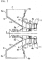
- FIG. 2 is an outline sectional view that shows the constitution around the intake duct of the compressor of the present embodiment.
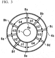
- FIG. 3 is a drawing that shows the arrangement relationship of the struts, which are used in the compressor of the present invention, in the circumferential direction of the rotor shaft.
- the inner casing 4a extends until the distal end of the rotor shaft 5, with the distal end thereof having a bent structure toward the peripheral direction, and the annular intake casing 6a is connected to this bent distal end.
- the outer casing 4b is curved closer to the side of the compressor 1 than the inner casing 4a, with a curved portion 41 having a bell mouth structure that is swollen toward the inside wall of the intake casing 6a.
- the respective side surfaces of the intake casings 6a, 6b are connected, and the intake duct 6 is formed provided with the annular space 10 by the intake casings 6a, 6b, the inner casing 4a, and the outer casing 4b.
- the suction port 7 for drawing in open air from the upside is formed by forming the upside of this intake duct 6 open.
- the struts 8 that are provided in a radial pattern centered on the rotor shaft 5 are connected to the inner side of the curved portion 41 of the outer casing 4b as well as the inner casing 4a. With these struts 8, the inner casing 4a and the outer casing 4b are supported at the inlet of the compressor 1. Also, the respective connection positions of the struts 8 with the inner casing 4a and the outer casing 4b are mostly in agreement in the axial direction of the rotor shaft 5.
- the spacing of struts 8a, 8b and struts 8e, 8f is angle ⁇ 1
- the spacing of struts 8b, 8c and struts 8f, 8g is angle ⁇ 2
- the spacing of struts 8c, 8d and struts 8g, 8h is angle ⁇ 3
- the spacing of struts 8d, 8e and struts 8h, 8a is angle ⁇ 4.
- angles ⁇ 1 to ⁇ 3 are 40 degrees, and the angle ⁇ 4 is 60 degrees, so that the difference between the value of angle ⁇ min that is the minimum value in angles ⁇ 1 to 04 and the value of angle ⁇ max the maximum value is set to at least 15 degrees.
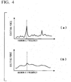
- FIG. 4 expressed by the exciting force the frequency distribution of the total pressure of the air that flows into the downstream of the struts 8, that is, shows the frequency distribution of variance amplitudes of the total pressure of the flow downstream of the struts and upstream of the IGV.
- the number of the struts 8 it is not limited to eight, and so long as a number is provided that is capable of sufficiently supporting the inner casing 4a and the outer casing 4b, it may be more than or less than eight. Note that since a pressure drop occurs due to the wake generated by the struts 8 as described above, it is preferable for the number of the struts 8 to be as few as possible in order to reduce the pressure drop of the air that is flowed into the compressor 1.
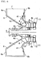
- FIG. 6 is an outline sectional view that shows the constitution around the intake duct of the compressor of the present embodiment. Those portions that are the same as the constitution of FIG 2 are denoted by the same reference numerals, and so a detailed description thereof shall be omitted.
- the strut 8 has a shape that, heading toward the periphery of the rotor shaft 5, slopes to the downstream in the axial direction of the rotor shaft 5 so that the connection position A of the strut 8 at the inner casing 4a is further upstream compared to the connection position B at the outer casing 4b.
- a distance d from the distal end of the curved portion 41 of the outer casing 4b to the connection position B of the strut 8 at the outer casing 4b becomes longer compared to the case of the constitution of FIG 2 .
- the shape of the strut 8 slope toward the trailing edge (the downstream in the axial direction of the rotor shaft 5) as in FIG. 6 , it is possible to lengthen the distance from the entrance of the air flow path 13 to the strut 8, heading from the inner casing 4a side to the outer casing 4b. Therefore, it is possible to put the flow velocity distribution of air at the leading edge of the strut 8 (the edge at the upstream in the axial direction of the rotor shaft 5) in an approximately equivalent state. Thereby, it is possible to make the flow of air that flows into the strut 8 a more uniform flow, and it is possible to reduce pressure loss at the side of the connection position with the outer casing 4b (the tip side).
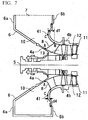
- connection position B with the outer casing 4b is positioned further to the downstream compared to the connection position A with the inner casing 4a. Accordingly, in the plurality of the struts 8, the distance d from the distal end C of the curved portion 41 of the outer casing 4b to the connection position B is the same.
- the distance d1 may be made longer than the distance d4.
- the harmonic component in the frequency component distribution of the total pressure of the air that flows in to the downstream of the strut 8 may be reduced, and the degree of freedom in the blade design of the compressor 1 may be increased.
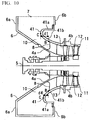
- FIG 9 is an outline sectional view that shows the constitution around the intake duct of the compressor of the present embodiment. Those portions that are the same as the constitution of FIG 2 are denoted by the same reference numerals, and so a detailed description thereof shall be omitted.
- the curved portion 41 of the outer casing 4b has a constitution of projecting further to the side of the intake casing 6a. Accordingly, in the periphery side of the curved portion 41, a flat portion 41a is formed that becomes a surface that is approximately parallel with the peripheral surface of the rotor shaft 5 (a surface approximately perpendicular to the intake casing 6b).
- a cross section of the flat portion 41 a from the distal end of the intake casing 6a side toward the inner side thereof forms a curved surface portion 41b having a U-shape in which the distal end thereof faces the side of the intake casing 6a.
- the flat portion 41a is provided in the curved portion 41 so as to project into the intake duct 6. Since it is possible to put the distribution of the flow of air that flows into the air flow path 13 into a state of being approximately even with respect to the radial direction and circumferential direction of the rotor shaft 5 and reduce drifts, it is possible to suppress a drop in efficiency of the compressor.
- the curved portion 41 of the outer casing 4b is made to have the same cross-sectional shape with respect to the circumferential direction of the rotor shaft 5. But as shown in FIG. 10 , the length in the axial direction of the flat portion 41a at a position near the suction port 7 may be made to become longer than the length in the axial direction of the flat portion 41a at a portion far from the suction port 7.
- the distance d1 becomes longer than the distance d4.
- the position that is far from the suction port 7 may be made into the same bell mouth shape as in FIG. 2 without the flat portion 41 a being constituted in the curved portion 41.
- the distance d when changing the distance d from the distal end C of the curved portion 41 of the outer casing 4b to the connection position B with the outer casing 4b depending on the position in the circumferential direction of the curved portion 41, it may be arranged in the following manner.
- the harmonic component in the frequency component distribution of the total pressures of the air that flows in to the downstream of the strut 8 may be reduced, and the degree of freedom in the blade design of the compressor 1 may be increased.
- the flow velocity distribution of air at the leading edge of the strut 8 may be put in an approximately equivalent state by the connection position B of the strut 8 with the outer casing 4b being positioned further downstream compared to the connection position A thereof with the inner casing 4a.
- the compressor of the present invention can be applied to a compressor having a single suction structure provided with an annular space centered on a rotor shaft and with a suction port opened at one side. Also, it may be applied to a compressor that is constituted to have the same axis as a gas turbine that is rotationally driven by combustion gas.
Landscapes
- Engineering & Computer Science (AREA)
- Mechanical Engineering (AREA)
- General Engineering & Computer Science (AREA)
- Chemical & Material Sciences (AREA)
- Combustion & Propulsion (AREA)
- Physics & Mathematics (AREA)
- Geometry (AREA)
- Structures Of Non-Positive Displacement Pumps (AREA)
Claims (11)
- Compresseur (1) comprenant :un carter (4a) intérieur disposé de manière à recouvrir un arbre (5) de rotor ;un carter (4b) extérieur disposé de manière à recouvrir le carter (4a) intérieur et à former un trajet (13) d'écoulement de fluide autour de l'arbre (5) du rotor etune aube (11) statorique d'un premier étage du compresseur (1) ;caractérisé en ce quele compresseur (1) comprend une pluralité d'entretoises (8) montées dans l'entrée du trajet (13) d'écoulement de fluide à un étage avant l'aube (11) statorique du premier étage du compresseur (1) et entre le carter (4a) intérieur et le carter (4b) extérieur, pour supporter le carter (4a) intérieur et le carter (4b) extérieur,dans lequel la pluralité d'entretoises (8) est disposée suivant une configuration radiale centrée sur l'arbre (5) du rotor et les intervalles entre au moins certaines des entretoises (8) voisines dans la direction circonférentielle de l'arbre (58) du rotor sont inégaux.
- Compresseur suivant la revendication 1, dans lequel n entretoises sont disposées dans la direction circonférentielle de l'arbre (5) du rotor, n étant un nombre entier supérieur ou égal à 2 et
la différence entre la valeur maximum et la valeur minimum de l'angle (θ) exprimant les intervalles des entretoises (8) voisines ramené au centre de l'arbre (5) du rotor est d'au moins 120 degrés/n. - Compresseur (1) suivant la revendication 1 ou la revendication 2, comprenant, en outre :un premier carter (6a), qui est relié au carter (4a) intérieur à l'extrémité d'entrée du trajet (13) d'écoulement de fluide etun deuxième carter (6b), qui est relié au carter (4b) extérieur à l'extrémité d'entrée du trajet (13) d'écoulement de fluide, dans lequel une partie (41) incurvée, qui s'incurve de manière à faire saillie vers le premier carter (6a), est formée à la partie de liaison du carter (4b) extérieur au deuxième carter (6b).
- Compresseur (1) suivant la revendication 3, dans lequel la partie (41) incurvée comprend, en outre :une partie (41a) plane, qui est voisine du deuxième carter (6b) et qui consiste en une surface qui est à peu près parallèle à la surface périphérique de l'arbre (5) du rotor etune surface (41b) incurvée, qui s'incurve doucement vers l'intérieur dans la direction radiale de l'arbre (5) du rotor à partir de l'extrémité distale de la partie (41a) plane, dans lequelune section transversale de la partie (41) incurvée forme à peu près un U, qui fait saillie vers le premier carter (6a).
- Compresseur (1) suivant la revendication 3 ou la revendication 4, dans lequel les parties de liaison des entretoises (8) au carter (4b) extérieur sont placées plus vers l'aval dans la direction axiale de l'arbre (5) du rotor que l'extrémité distale de la partie (41) incurvée.
- Compresseur (1) suivant la revendication 4 ou la revendication 5, dans lequel, dans la partie (41a) plane, qui est formée sous une forme annulaire dans la direction circonférentielle de l'arbre (5) du rotor, la longueur dans la direction axiale d'une première partie voisine d'un orifice (7) ouvert d'aspiration d'air, qui est formée à l'extrémité distale du premier carter (6a) et du deuxième carter (6b), est plus grande que la longueur dans la direction axiale d'une deuxième partie, qui est placée plus loin de l'orifice (7) d'aspiration que ne l'est la première partie.
- Compresseur (1) suivant l'une quelconque des revendications 3 à 6, dans lequel, dans la partie (41) incurvée, qui est formée sous une forme annulaire dans la direction circonférentielle de l'arbre (5) du rotor, l'extrémité distale d'une/de la première partie, qui est voisine d'un/de l'orifice (7) ouvert d'aspiration d'air, qui est formé à l'extrémité distale du premier carter (6a) et du deuxième carter (6b), fait saillie davantage vers le premier carter (6a) que l'extrémité distale d'une/de la deuxième partie, qui est placée plus loin de l'orifice (7) d'aspiration que ne l'est la première partie.
- Compresseur (1) suivant l'une quelconque des revendications 1 à 7, dans lequel les parties de liaison des entretoises (8) au carter (4b) extérieur sont placées plus en aval dans la direction axiale de l'arbre (5) du rotor que les parties de liaison des entretoises (8) au carter (4a) intérieur.
- Compresseur (1) suivant la revendication 8, dans lequel les entretoises (8) sont d'autant plus proches d'un/de l'orifice (7) d'aspiration d'air atmosphérique, qui est formé à l'extrémité distale d'un/ du premier carter (6a) et d'un/du deuxième carter (6b), que la distance dans la direction axiale de la partie de liaison des entretoises (8) au carter (4b) extérieur et que la distance dans la direction axiale de la partie de liaison des entretoises (8) au carter (4a) intérieur sont plus grandes.
- Compresseur (1) suivant l'une quelconque des revendications 1 à 9, dans lequel un conduit (6) d'admission d'une structure unique d'aspiration qui est pourvu d'un orifice (7) d'aspiration pour aspirer de l'air, à envoyer au compresseur (1) à partir de l'air atmosphérique, dans une direction perpendiculaire à l'arbre (5) du rotor, est disposé en amont au compresseur (1).
- Turbine à gaz équipée d'un compresseur (1) suivant l'une quelconque des revendications 1 à 10.
Applications Claiming Priority (2)
| Application Number | Priority Date | Filing Date | Title |
|---|---|---|---|
| JP2006343814 | 2006-12-21 | ||
| PCT/JP2007/074575 WO2008075747A1 (fr) | 2006-12-21 | 2007-12-20 | Compresseur |
Publications (3)
| Publication Number | Publication Date |
|---|---|
| EP2096321A1 EP2096321A1 (fr) | 2009-09-02 |
| EP2096321A4 EP2096321A4 (fr) | 2013-06-05 |
| EP2096321B1 true EP2096321B1 (fr) | 2017-03-22 |
Family
ID=39536375
Family Applications (1)
| Application Number | Title | Priority Date | Filing Date |
|---|---|---|---|
| EP07851000.5A Revoked EP2096321B1 (fr) | 2006-12-21 | 2007-12-20 | Compresseur |
Country Status (6)
| Country | Link |
|---|---|
| US (1) | US8206097B2 (fr) |
| EP (1) | EP2096321B1 (fr) |
| JP (1) | JP5222152B2 (fr) |
| KR (1) | KR101191060B1 (fr) |
| CN (1) | CN101542129B (fr) |
| WO (1) | WO2008075747A1 (fr) |
Cited By (1)
| Publication number | Priority date | Publication date | Assignee | Title |
|---|---|---|---|---|
| EP4177442A1 (fr) * | 2021-11-03 | 2023-05-10 | Pratt & Whitney Canada Corp. | Entretoise d'entrée d'air pour moteur d'aéronef |
Families Citing this family (15)
| Publication number | Priority date | Publication date | Assignee | Title |
|---|---|---|---|---|
| JP5479021B2 (ja) * | 2009-10-16 | 2014-04-23 | 三菱重工業株式会社 | 排気ターボ過給機のコンプレッサ |
| US8684685B2 (en) * | 2010-10-20 | 2014-04-01 | General Electric Company | Rotary machine having grooves for control of fluid dynamics |
| US8678752B2 (en) * | 2010-10-20 | 2014-03-25 | General Electric Company | Rotary machine having non-uniform blade and vane spacing |
| JP5804745B2 (ja) * | 2011-03-30 | 2015-11-04 | 三菱重工業株式会社 | 流体機械の吸込ケーシングおよび流体機械 |
| US9091206B2 (en) * | 2011-09-14 | 2015-07-28 | General Electric Company | Systems and methods for inlet fogging control |
| WO2014203368A1 (fr) * | 2013-06-20 | 2014-12-24 | 三菱重工業株式会社 | Appareil de guidage de gaz et équipement le comportant |
| JP6134628B2 (ja) | 2013-10-17 | 2017-05-24 | 三菱重工業株式会社 | 軸流式の圧縮機、及びガスタービン |
| DE102013224081B4 (de) * | 2013-11-26 | 2015-11-05 | Man Diesel & Turbo Se | Verdichter |
| US10094223B2 (en) | 2014-03-13 | 2018-10-09 | Pratt & Whitney Canada Corp. | Integrated strut and IGV configuration |
| JP6661323B2 (ja) * | 2015-10-14 | 2020-03-11 | 川崎重工業株式会社 | 圧縮機の吸気構造 |
| CN105508015B (zh) * | 2016-01-22 | 2020-04-24 | 上海博泽电机有限公司 | 一种低旋转噪声的汽车发动机冷却风扇 |
| DE102017200754A1 (de) | 2017-01-18 | 2018-07-19 | Siemens Aktiengesellschaft | Einströmleitgitter, Einströmungsanordnung, Turbomaschine |
| US12060891B2 (en) * | 2021-10-25 | 2024-08-13 | Pratt & Whitney Canada Corp. | Centrifugal compressor having a bellmouth with a stiffening member |
| KR102786958B1 (ko) * | 2022-02-25 | 2025-03-27 | 두산에너빌리티 주식회사 | 공기 인렛 매니폴드 및 이를 포함하는 가스터빈 |
| JP7657358B1 (ja) * | 2024-10-22 | 2025-04-04 | 三菱重工業株式会社 | 吸気ケーシング、この吸気ケーシングを備える軸流圧縮機、この軸流圧縮機を備えるガスタービン |
Citations (5)
| Publication number | Priority date | Publication date | Assignee | Title |
|---|---|---|---|---|
| US5342167A (en) | 1992-10-09 | 1994-08-30 | Airflow Research And Manufacturing Corporation | Low noise fan |
| WO2002092969A1 (fr) | 2001-05-11 | 2002-11-21 | Snecma Moteurs | Structure comprenant un rotor et des sources de perturbations fixes et procede de reduction de vibrations dans cette structure |
| WO2004022980A1 (fr) | 2002-09-06 | 2004-03-18 | Honeywell International Inc. | Pattes aperiodiques pour de meilleures reponses des pales |
| EP1621741A1 (fr) | 2004-07-28 | 2006-02-01 | Hitachi, Ltd. | Turbine à gaz |
| US20060257252A1 (en) | 2005-05-13 | 2006-11-16 | Valeo Electrical Systems, Inc. | Fan shroud supports which increase resonant frequency |
Family Cites Families (11)
| Publication number | Priority date | Publication date | Assignee | Title |
|---|---|---|---|---|
| US3116789A (en) * | 1960-03-14 | 1964-01-07 | Rolls Royce | Heat exchange apparatus, e. g. for use in gas turbine engines |
| JPS4924005B1 (fr) * | 1967-09-28 | 1974-06-20 | ||
| JPS5525555A (en) * | 1978-08-12 | 1980-02-23 | Hitachi Ltd | Impeller |
| JPS57176400A (en) * | 1981-04-24 | 1982-10-29 | Hitachi Ltd | Axial flow compressor |
| JPH06146922A (ja) * | 1992-10-30 | 1994-05-27 | Toshiba Corp | 空気圧縮機のケーシング |
| JPH0717994A (ja) | 1993-06-30 | 1995-01-20 | Tokyo Yatsuka Univ | デオキシリボヌクレオシド誘導体の合成法 |
| JPH0717994U (ja) | 1993-08-27 | 1995-03-31 | 三菱重工業株式会社 | 圧縮機の片吸い込み型吸気ケーシング |
| JP3567086B2 (ja) * | 1998-07-28 | 2004-09-15 | 株式会社東芝 | 送風羽根及び回転電機 |
| JP2000145699A (ja) * | 1998-11-11 | 2000-05-26 | Ishikawajima Harima Heavy Ind Co Ltd | ターボ形圧縮機 |
| US6439838B1 (en) * | 1999-12-18 | 2002-08-27 | General Electric Company | Periodic stator airfoils |
| ATE395506T1 (de) * | 2004-06-01 | 2008-05-15 | Volvo Aero Corp | Gasturbinen-kompressionssystem und verdichterstruktur |
-
2007
- 2007-12-20 KR KR1020097010371A patent/KR101191060B1/ko active Active
- 2007-12-20 JP JP2008550188A patent/JP5222152B2/ja active Active
- 2007-12-20 US US12/447,985 patent/US8206097B2/en active Active
- 2007-12-20 WO PCT/JP2007/074575 patent/WO2008075747A1/fr not_active Ceased
- 2007-12-20 CN CN2007800431015A patent/CN101542129B/zh active Active
- 2007-12-20 EP EP07851000.5A patent/EP2096321B1/fr not_active Revoked
Patent Citations (5)
| Publication number | Priority date | Publication date | Assignee | Title |
|---|---|---|---|---|
| US5342167A (en) | 1992-10-09 | 1994-08-30 | Airflow Research And Manufacturing Corporation | Low noise fan |
| WO2002092969A1 (fr) | 2001-05-11 | 2002-11-21 | Snecma Moteurs | Structure comprenant un rotor et des sources de perturbations fixes et procede de reduction de vibrations dans cette structure |
| WO2004022980A1 (fr) | 2002-09-06 | 2004-03-18 | Honeywell International Inc. | Pattes aperiodiques pour de meilleures reponses des pales |
| EP1621741A1 (fr) | 2004-07-28 | 2006-02-01 | Hitachi, Ltd. | Turbine à gaz |
| US20060257252A1 (en) | 2005-05-13 | 2006-11-16 | Valeo Electrical Systems, Inc. | Fan shroud supports which increase resonant frequency |
Non-Patent Citations (2)
| Title |
|---|
| JÖRG SEUME: "Stationäre Gasturbinen", 2003, SPRINGER-VERLAG, pages: 48-52,674 - 680,719-723, XP055443549 |
| SIEMENS AG: "Gasturbinen und Gasturbinenkraftwerke", PROSPEKT A19100-U111-A210, October 1990 (1990-10-01), pages 15, XP055443535 |
Cited By (2)
| Publication number | Priority date | Publication date | Assignee | Title |
|---|---|---|---|---|
| EP4177442A1 (fr) * | 2021-11-03 | 2023-05-10 | Pratt & Whitney Canada Corp. | Entretoise d'entrée d'air pour moteur d'aéronef |
| US11719165B2 (en) | 2021-11-03 | 2023-08-08 | Pratt & Whitney Canada Corp. | Air inlet strut for aircraft engine |
Also Published As
| Publication number | Publication date |
|---|---|
| KR20090074082A (ko) | 2009-07-03 |
| JPWO2008075747A1 (ja) | 2010-04-15 |
| CN101542129A (zh) | 2009-09-23 |
| KR101191060B1 (ko) | 2012-10-15 |
| US8206097B2 (en) | 2012-06-26 |
| US20100068044A1 (en) | 2010-03-18 |
| JP5222152B2 (ja) | 2013-06-26 |
| WO2008075747A1 (fr) | 2008-06-26 |
| EP2096321A4 (fr) | 2013-06-05 |
| CN101542129B (zh) | 2012-12-19 |
| EP2096321A1 (fr) | 2009-09-02 |
Similar Documents
| Publication | Publication Date | Title |
|---|---|---|
| US8206097B2 (en) | Compressor | |
| JP6067095B2 (ja) | 遠心圧縮機 | |
| US10480531B2 (en) | Axial flow compressor, gas turbine including the same, and stator blade of axial flow compressor | |
| CN102119268B (zh) | 燃气轮机中使用的具有带排气口的线性流动路径的过渡件 | |
| EP2096319B1 (fr) | Compresseur centrifuge | |
| US20090317232A1 (en) | Blade shroud with aperture | |
| US8834116B2 (en) | Fluid flow machine with peripheral energization near the suction side | |
| EP3159504B1 (fr) | Turbine axiale de type radiale et turbocompresseur de suralimentation | |
| JP2005524800A (ja) | 独立通路ディフューザ | |
| US20160115971A1 (en) | Diffuser pipe with splitter vane | |
| EP3176442B1 (fr) | Dispositif à écoulement axial avec traitement du carter et moteur à réaction | |
| WO2018146753A1 (fr) | Compresseur centrifuge et turbocompresseur | |
| JP2017519154A (ja) | 遠心圧縮機用のディフューザ | |
| KR20140099200A (ko) | 축류 터빈 및 이를 포함하는 터보 과급기 | |
| EP3708804B1 (fr) | Cavité de pointe d'hélice | |
| CN112177949A (zh) | 多级离心压缩机 | |
| EP3705698B1 (fr) | Turbine et turbocompresseur | |
| EP3705697A1 (fr) | Turbine et turbocompresseur | |
| CN110312852A (zh) | 涡轮及燃气轮机 | |
| JP2018135815A (ja) | 遠心回転機械 | |
| CN115427665B (zh) | 涡轮以及具备该涡轮的涡轮增压器 | |
| US10975881B2 (en) | Centrifugal impeller for a turbine engine | |
| JP5781461B2 (ja) | 圧縮機 | |
| JP7643214B2 (ja) | 遠心式回転装置 | |
| JP7651986B2 (ja) | 遠心式回転装置 |
Legal Events
| Date | Code | Title | Description |
|---|---|---|---|
| PUAI | Public reference made under article 153(3) epc to a published international application that has entered the european phase |
Free format text: ORIGINAL CODE: 0009012 |
|
| 17P | Request for examination filed |
Effective date: 20090428 |
|
| AK | Designated contracting states |
Kind code of ref document: A1 Designated state(s): AT BE BG CH CY CZ DE DK EE ES FI FR GB GR HU IE IS IT LI LT LU LV MC MT NL PL PT RO SE SI SK TR |
|
| DAX | Request for extension of the european patent (deleted) | ||
| REG | Reference to a national code |
Ref country code: DE Ref legal event code: R079 Ref document number: 602007050327 Country of ref document: DE Free format text: PREVIOUS MAIN CLASS: F04D0029540000 Ipc: F04D0029520000 |
|
| A4 | Supplementary search report drawn up and despatched |
Effective date: 20130507 |
|
| RIC1 | Information provided on ipc code assigned before grant |
Ipc: F04D 29/66 20060101ALI20130430BHEP Ipc: F04D 29/54 20060101ALI20130430BHEP Ipc: F04D 29/52 20060101AFI20130430BHEP |
|
| RAP1 | Party data changed (applicant data changed or rights of an application transferred) |
Owner name: MITSUBISHI HITACHI POWER SYSTEMS, LTD. |
|
| RAP1 | Party data changed (applicant data changed or rights of an application transferred) |
Owner name: MITSUBISHI HITACHI POWER SYSTEMS, LTD. |
|
| 17Q | First examination report despatched |
Effective date: 20160520 |
|
| GRAP | Despatch of communication of intention to grant a patent |
Free format text: ORIGINAL CODE: EPIDOSNIGR1 |
|
| INTG | Intention to grant announced |
Effective date: 20161024 |
|
| GRAS | Grant fee paid |
Free format text: ORIGINAL CODE: EPIDOSNIGR3 |
|
| STAA | Information on the status of an ep patent application or granted ep patent |
Free format text: STATUS: GRANT OF PATENT IS INTENDED |
|
| GRAA | (expected) grant |
Free format text: ORIGINAL CODE: 0009210 |
|
| STAA | Information on the status of an ep patent application or granted ep patent |
Free format text: STATUS: THE PATENT HAS BEEN GRANTED |
|
| AK | Designated contracting states |
Kind code of ref document: B1 Designated state(s): AT BE BG CH CY CZ DE DK EE ES FI FR GB GR HU IE IS IT LI LT LU LV MC MT NL PL PT RO SE SI SK TR |
|
| REG | Reference to a national code |
Ref country code: GB Ref legal event code: FG4D |
|
| REG | Reference to a national code |
Ref country code: CH Ref legal event code: EP |
|
| REG | Reference to a national code |
Ref country code: AT Ref legal event code: REF Ref document number: 878081 Country of ref document: AT Kind code of ref document: T Effective date: 20170415 |
|
| REG | Reference to a national code |
Ref country code: IE Ref legal event code: FG4D |
|
| REG | Reference to a national code |
Ref country code: DE Ref legal event code: R096 Ref document number: 602007050327 Country of ref document: DE |
|
| REG | Reference to a national code |
Ref country code: NL Ref legal event code: MP Effective date: 20170322 |
|
| PG25 | Lapsed in a contracting state [announced via postgrant information from national office to epo] |
Ref country code: LT Free format text: LAPSE BECAUSE OF FAILURE TO SUBMIT A TRANSLATION OF THE DESCRIPTION OR TO PAY THE FEE WITHIN THE PRESCRIBED TIME-LIMIT Effective date: 20170322 Ref country code: FI Free format text: LAPSE BECAUSE OF FAILURE TO SUBMIT A TRANSLATION OF THE DESCRIPTION OR TO PAY THE FEE WITHIN THE PRESCRIBED TIME-LIMIT Effective date: 20170322 Ref country code: GR Free format text: LAPSE BECAUSE OF FAILURE TO SUBMIT A TRANSLATION OF THE DESCRIPTION OR TO PAY THE FEE WITHIN THE PRESCRIBED TIME-LIMIT Effective date: 20170623 |
|
| REG | Reference to a national code |
Ref country code: LT Ref legal event code: MG4D |
|
| REG | Reference to a national code |
Ref country code: AT Ref legal event code: MK05 Ref document number: 878081 Country of ref document: AT Kind code of ref document: T Effective date: 20170322 |
|
| PG25 | Lapsed in a contracting state [announced via postgrant information from national office to epo] |
Ref country code: SE Free format text: LAPSE BECAUSE OF FAILURE TO SUBMIT A TRANSLATION OF THE DESCRIPTION OR TO PAY THE FEE WITHIN THE PRESCRIBED TIME-LIMIT Effective date: 20170322 Ref country code: BG Free format text: LAPSE BECAUSE OF FAILURE TO SUBMIT A TRANSLATION OF THE DESCRIPTION OR TO PAY THE FEE WITHIN THE PRESCRIBED TIME-LIMIT Effective date: 20170622 Ref country code: LV Free format text: LAPSE BECAUSE OF FAILURE TO SUBMIT A TRANSLATION OF THE DESCRIPTION OR TO PAY THE FEE WITHIN THE PRESCRIBED TIME-LIMIT Effective date: 20170322 |
|
| PG25 | Lapsed in a contracting state [announced via postgrant information from national office to epo] |
Ref country code: NL Free format text: LAPSE BECAUSE OF FAILURE TO SUBMIT A TRANSLATION OF THE DESCRIPTION OR TO PAY THE FEE WITHIN THE PRESCRIBED TIME-LIMIT Effective date: 20170322 |
|
| PG25 | Lapsed in a contracting state [announced via postgrant information from national office to epo] |
Ref country code: AT Free format text: LAPSE BECAUSE OF FAILURE TO SUBMIT A TRANSLATION OF THE DESCRIPTION OR TO PAY THE FEE WITHIN THE PRESCRIBED TIME-LIMIT Effective date: 20170322 Ref country code: IT Free format text: LAPSE BECAUSE OF FAILURE TO SUBMIT A TRANSLATION OF THE DESCRIPTION OR TO PAY THE FEE WITHIN THE PRESCRIBED TIME-LIMIT Effective date: 20170322 Ref country code: RO Free format text: LAPSE BECAUSE OF FAILURE TO SUBMIT A TRANSLATION OF THE DESCRIPTION OR TO PAY THE FEE WITHIN THE PRESCRIBED TIME-LIMIT Effective date: 20170322 Ref country code: ES Free format text: LAPSE BECAUSE OF FAILURE TO SUBMIT A TRANSLATION OF THE DESCRIPTION OR TO PAY THE FEE WITHIN THE PRESCRIBED TIME-LIMIT Effective date: 20170322 Ref country code: CZ Free format text: LAPSE BECAUSE OF FAILURE TO SUBMIT A TRANSLATION OF THE DESCRIPTION OR TO PAY THE FEE WITHIN THE PRESCRIBED TIME-LIMIT Effective date: 20170322 Ref country code: EE Free format text: LAPSE BECAUSE OF FAILURE TO SUBMIT A TRANSLATION OF THE DESCRIPTION OR TO PAY THE FEE WITHIN THE PRESCRIBED TIME-LIMIT Effective date: 20170322 Ref country code: SK Free format text: LAPSE BECAUSE OF FAILURE TO SUBMIT A TRANSLATION OF THE DESCRIPTION OR TO PAY THE FEE WITHIN THE PRESCRIBED TIME-LIMIT Effective date: 20170322 |
|
| PG25 | Lapsed in a contracting state [announced via postgrant information from national office to epo] |
Ref country code: PT Free format text: LAPSE BECAUSE OF FAILURE TO SUBMIT A TRANSLATION OF THE DESCRIPTION OR TO PAY THE FEE WITHIN THE PRESCRIBED TIME-LIMIT Effective date: 20170724 Ref country code: IS Free format text: LAPSE BECAUSE OF FAILURE TO SUBMIT A TRANSLATION OF THE DESCRIPTION OR TO PAY THE FEE WITHIN THE PRESCRIBED TIME-LIMIT Effective date: 20170722 Ref country code: PL Free format text: LAPSE BECAUSE OF FAILURE TO SUBMIT A TRANSLATION OF THE DESCRIPTION OR TO PAY THE FEE WITHIN THE PRESCRIBED TIME-LIMIT Effective date: 20170322 |
|
| REG | Reference to a national code |
Ref country code: DE Ref legal event code: R026 Ref document number: 602007050327 Country of ref document: DE |
|
| PLBI | Opposition filed |
Free format text: ORIGINAL CODE: 0009260 |
|
| PLAX | Notice of opposition and request to file observation + time limit sent |
Free format text: ORIGINAL CODE: EPIDOSNOBS2 |
|
| 26 | Opposition filed |
Opponent name: SIEMENS AKTIENGESELLSCHAFT Effective date: 20171212 |
|
| PG25 | Lapsed in a contracting state [announced via postgrant information from national office to epo] |
Ref country code: DK Free format text: LAPSE BECAUSE OF FAILURE TO SUBMIT A TRANSLATION OF THE DESCRIPTION OR TO PAY THE FEE WITHIN THE PRESCRIBED TIME-LIMIT Effective date: 20170322 |
|
| PG25 | Lapsed in a contracting state [announced via postgrant information from national office to epo] |
Ref country code: SI Free format text: LAPSE BECAUSE OF FAILURE TO SUBMIT A TRANSLATION OF THE DESCRIPTION OR TO PAY THE FEE WITHIN THE PRESCRIBED TIME-LIMIT Effective date: 20170322 |
|
| PLAF | Information modified related to communication of a notice of opposition and request to file observations + time limit |
Free format text: ORIGINAL CODE: EPIDOSCOBS2 |
|
| PLBB | Reply of patent proprietor to notice(s) of opposition received |
Free format text: ORIGINAL CODE: EPIDOSNOBS3 |
|
| REG | Reference to a national code |
Ref country code: CH Ref legal event code: PL |
|
| GBPC | Gb: european patent ceased through non-payment of renewal fee |
Effective date: 20171220 |
|
| REG | Reference to a national code |
Ref country code: IE Ref legal event code: MM4A |
|
| PG25 | Lapsed in a contracting state [announced via postgrant information from national office to epo] |
Ref country code: LU Free format text: LAPSE BECAUSE OF NON-PAYMENT OF DUE FEES Effective date: 20171220 Ref country code: MT Free format text: LAPSE BECAUSE OF NON-PAYMENT OF DUE FEES Effective date: 20171220 |
|
| REG | Reference to a national code |
Ref country code: FR Ref legal event code: ST Effective date: 20180831 |
|
| REG | Reference to a national code |
Ref country code: BE Ref legal event code: MM Effective date: 20171231 |
|
| PG25 | Lapsed in a contracting state [announced via postgrant information from national office to epo] |
Ref country code: IE Free format text: LAPSE BECAUSE OF NON-PAYMENT OF DUE FEES Effective date: 20171220 Ref country code: FR Free format text: LAPSE BECAUSE OF NON-PAYMENT OF DUE FEES Effective date: 20180102 |
|
| PG25 | Lapsed in a contracting state [announced via postgrant information from national office to epo] |
Ref country code: LI Free format text: LAPSE BECAUSE OF NON-PAYMENT OF DUE FEES Effective date: 20171231 Ref country code: BE Free format text: LAPSE BECAUSE OF NON-PAYMENT OF DUE FEES Effective date: 20171231 Ref country code: CH Free format text: LAPSE BECAUSE OF NON-PAYMENT OF DUE FEES Effective date: 20171231 Ref country code: GB Free format text: LAPSE BECAUSE OF NON-PAYMENT OF DUE FEES Effective date: 20171220 |
|
| PG25 | Lapsed in a contracting state [announced via postgrant information from national office to epo] |
Ref country code: MC Free format text: LAPSE BECAUSE OF FAILURE TO SUBMIT A TRANSLATION OF THE DESCRIPTION OR TO PAY THE FEE WITHIN THE PRESCRIBED TIME-LIMIT Effective date: 20170322 Ref country code: HU Free format text: LAPSE BECAUSE OF FAILURE TO SUBMIT A TRANSLATION OF THE DESCRIPTION OR TO PAY THE FEE WITHIN THE PRESCRIBED TIME-LIMIT; INVALID AB INITIO Effective date: 20071220 |
|
| REG | Reference to a national code |
Ref country code: DE Ref legal event code: R064 Ref document number: 602007050327 Country of ref document: DE Ref country code: DE Ref legal event code: R103 Ref document number: 602007050327 Country of ref document: DE |
|
| RDAF | Communication despatched that patent is revoked |
Free format text: ORIGINAL CODE: EPIDOSNREV1 |
|
| PG25 | Lapsed in a contracting state [announced via postgrant information from national office to epo] |
Ref country code: CY Free format text: LAPSE BECAUSE OF NON-PAYMENT OF DUE FEES Effective date: 20170322 |
|
| RDAG | Patent revoked |
Free format text: ORIGINAL CODE: 0009271 |
|
| STAA | Information on the status of an ep patent application or granted ep patent |
Free format text: STATUS: PATENT REVOKED |
|
| PGFP | Annual fee paid to national office [announced via postgrant information from national office to epo] |
Ref country code: DE Payment date: 20191210 Year of fee payment: 13 |
|
| 27W | Patent revoked |
Effective date: 20190903 |
|
| REG | Reference to a national code |
Ref country code: FI Ref legal event code: MGE |
|
| PG25 | Lapsed in a contracting state [announced via postgrant information from national office to epo] |
Ref country code: TR Free format text: LAPSE BECAUSE OF FAILURE TO SUBMIT A TRANSLATION OF THE DESCRIPTION OR TO PAY THE FEE WITHIN THE PRESCRIBED TIME-LIMIT Effective date: 20170322 |