EP2096396A2 - Caloporteur pour milieux liquides - Google Patents
Caloporteur pour milieux liquides Download PDFInfo
- Publication number
- EP2096396A2 EP2096396A2 EP09153885A EP09153885A EP2096396A2 EP 2096396 A2 EP2096396 A2 EP 2096396A2 EP 09153885 A EP09153885 A EP 09153885A EP 09153885 A EP09153885 A EP 09153885A EP 2096396 A2 EP2096396 A2 EP 2096396A2
- Authority
- EP
- European Patent Office
- Prior art keywords
- heat exchanger
- flow
- channels
- exchanger according
- channel
- Prior art date
- Legal status (The legal status is an assumption and is not a legal conclusion. Google has not performed a legal analysis and makes no representation as to the accuracy of the status listed.)
- Withdrawn
Links
Images




Classifications
-
- F—MECHANICAL ENGINEERING; LIGHTING; HEATING; WEAPONS; BLASTING
- F28—HEAT EXCHANGE IN GENERAL
- F28D—HEAT-EXCHANGE APPARATUS, NOT PROVIDED FOR IN ANOTHER SUBCLASS, IN WHICH THE HEAT-EXCHANGE MEDIA DO NOT COME INTO DIRECT CONTACT
- F28D9/00—Heat-exchange apparatus having stationary plate-like or laminated conduit assemblies for both heat-exchange media, the media being in contact with different sides of a conduit wall
- F28D9/0025—Heat-exchange apparatus having stationary plate-like or laminated conduit assemblies for both heat-exchange media, the media being in contact with different sides of a conduit wall the conduits being formed by zig-zag bend plates
-
- B—PERFORMING OPERATIONS; TRANSPORTING
- B21—MECHANICAL METAL-WORKING WITHOUT ESSENTIALLY REMOVING MATERIAL; PUNCHING METAL
- B21D—WORKING OR PROCESSING OF SHEET METAL OR METAL TUBES, RODS OR PROFILES WITHOUT ESSENTIALLY REMOVING MATERIAL; PUNCHING METAL
- B21D53/00—Making other particular articles
- B21D53/02—Making other particular articles heat exchangers or parts thereof, e.g. radiators, condensers fins, headers
-
- F—MECHANICAL ENGINEERING; LIGHTING; HEATING; WEAPONS; BLASTING
- F24—HEATING; RANGES; VENTILATING
- F24F—AIR-CONDITIONING; AIR-HUMIDIFICATION; VENTILATION; USE OF AIR CURRENTS FOR SCREENING
- F24F12/00—Use of energy recovery systems in air conditioning, ventilation or screening
- F24F12/001—Use of energy recovery systems in air conditioning, ventilation or screening with heat-exchange between supplied and exhausted air
- F24F12/006—Use of energy recovery systems in air conditioning, ventilation or screening with heat-exchange between supplied and exhausted air using an air-to-air heat exchanger
-
- F—MECHANICAL ENGINEERING; LIGHTING; HEATING; WEAPONS; BLASTING
- F24—HEATING; RANGES; VENTILATING
- F24F—AIR-CONDITIONING; AIR-HUMIDIFICATION; VENTILATION; USE OF AIR CURRENTS FOR SCREENING
- F24F13/00—Details common to, or for air-conditioning, air-humidification, ventilation or use of air currents for screening
- F24F13/30—Arrangement or mounting of heat-exchangers
-
- F—MECHANICAL ENGINEERING; LIGHTING; HEATING; WEAPONS; BLASTING
- F28—HEAT EXCHANGE IN GENERAL
- F28F—DETAILS OF HEAT-EXCHANGE AND HEAT-TRANSFER APPARATUS, OF GENERAL APPLICATION
- F28F9/00—Casings; Header boxes; Auxiliary supports for elements; Auxiliary members within casings
- F28F9/02—Header boxes; End plates
-
- Y—GENERAL TAGGING OF NEW TECHNOLOGICAL DEVELOPMENTS; GENERAL TAGGING OF CROSS-SECTIONAL TECHNOLOGIES SPANNING OVER SEVERAL SECTIONS OF THE IPC; TECHNICAL SUBJECTS COVERED BY FORMER USPC CROSS-REFERENCE ART COLLECTIONS [XRACs] AND DIGESTS
- Y02—TECHNOLOGIES OR APPLICATIONS FOR MITIGATION OR ADAPTATION AGAINST CLIMATE CHANGE
- Y02B—CLIMATE CHANGE MITIGATION TECHNOLOGIES RELATED TO BUILDINGS, e.g. HOUSING, HOUSE APPLIANCES OR RELATED END-USER APPLICATIONS
- Y02B30/00—Energy efficient heating, ventilation or air conditioning [HVAC]
- Y02B30/56—Heat recovery units
Definitions
- the invention relates to a heat exchanger for fluid media, in particular air, with in the direction of extension alternately successive channels for a first flow system and a second flow system, wherein the channels are formed by meandering folding a sheet material, with an edge cover in the region of the fold edges, and with a central cover in the central region of the Faltens decisivtel, wherein the media supply of the flow systems is transverse to the channels.
- Such a heat exchanger is for example from the DE 35 02 972 A1 known. Since channels with low channel heights or low flow velocities are required for good heat transfer, many channels must be connected in parallel to achieve high flow. In conventional plate heat exchangers, the individual plates in the edge areas must be tightly interconnected. Leakage often occurs here, which leads to undesirable heat losses. In the known heat exchanger, a plurality of edges is already well sealed by the fact that the sheet material is folded meander-shaped and thus a dense execution automatically takes place in the region of the folding saddles. The flow takes place in the known heat exchanger transversely to the individual channels and across Extension direction of the heat exchanger. In this way, a heat exchanger with a plurality of flow channels create that are each flowed evenly. A disadvantage of the known heat exchanger is that a large number of channels makes a large cross-section of the flow system at the location of the heat exchanger required. This leads to a large amount of space and still limits the number of usable channels in the heat exchanger.
- the problem underlying the invention is to provide a heat exchanger with which there is a good heat transfer at the same time high flow of the fluid medium and small footprint for the installation of the heat exchanger.
- a heat exchanger with a plurality of thin channels can be arranged quasi longitudinally in the flow channels of the flow system.
- the flow channels of the flow system need not be expanded in cross section. Since the location of the arrangement of the heat exchanger is almost arbitrary, can almost always find a flow channel piece with a suitable length.
- a development of the invention is characterized in that the media supply takes place by means of a flow distributor whose cross-section decreases depending on the total cross-section of the channels to be supplied supply side in the direction of current and increases downstream in the flow direction.
- the flow distributor may, for example, have an inclined partition wall in the region of the central cover.
- the cross section of the flow distributor can be progressively tapered progressively after branching off individual channels on the supply side or be further and further extended on the discharge side when the channels are opened.
- small channel thicknesses should be used. For example, with half the channel thickness, the same efficiency and the same pressure loss can be achieved with a quarter of the volume requirement for the heat exchanger to reach. For air, a channel thickness of less than 1.5 mm and for water less than 0.5 mm should be selected.
- Another development of the invention is characterized in that the channels are arranged parallel to each other. This parallel arrangement allows a simple and geometrically easily manageable construction. Preferably, the channels are operated in countercurrent. In this way, the best possible transfer of heat can be achieved.
- An advantageous embodiment of the invention is characterized in that the channels have such a cross section that an equal pressure loss is achieved for different streamlines.
- a deterioration of the efficiency of the heat exchanger can be prevented by a different entry of streamlines into the channels, as short flow paths and thus a short residence time in the channel a small channel thickness and long flow paths in the channel, that is, a long residence time large channel thickness is assigned.
- the channels at the closed end in the region of the folding saddles have a greater width than at the open end.
- means for achieving the desired pressure loss may be, for example, internals or profiles.
- the sheet material has poor heat conduction. In this way it is ensured that a heat transfer between the fluid media takes place in two adjacent channels. A deterioration of the heat transfer by an unwanted longitudinal line along the sheet material is thus prevented. It is advantageous if the sheet material has a small thickness and in particular is a film. Such thin materials and in particular films, for example of a suitable synthetic resin material, have a low heat conduction.
- the sheet material may consist of sheet metal, copper, aluminum, stainless steel, plastic, fabric or paper or be formed of multi-layered.
- the materials mentioned can be easily processed as continuous material and have the desired properties for a heat exchanger with a suitable selection. It is also possible to use a media-permeable material, for example a semipermeable membrane, for the sheet material. Another advantageous embodiment results in a coating of the sheet material with a hydrophobic layer.
- An advantageous embodiment of the invention results from spacers for a defined distance of the channel walls from each other. In this way it is ensured that the individual channels have similar characteristics and that the overall result of the heat exchanger is not adversely affected by individual malfunctioning channels.
- the sheet material may for example have an embossing. This embodiment is particularly easy to produce technical.
- the edge covers, the central covers and / or possibly present frontal covers are formed as housing plates or consist of self-adhesive film.
- the housing plates may be soldered together and / or with the fold package. This results in a stable, also for liquids particularly suitable embodiment. In this way, a robust and easy-to-assemble construction and, especially in the case of the embodiment with the self-adhesive film, a low material requirement and a simple construction of the heat exchanger result.
- a development of the invention is characterized by an arrangement in a flow channel, wherein the channels are arranged transversely to the flow channel.
- This arrangement makes the assembly, construction and parts requirements of the flow system particularly simple, while at the same time requiring only little space.
- an arrangement of the heat exchanger may be provided in a muffler housing. Since heat recovery systems in low energy houses generally have mufflers to reduce the noise pollution, here an arrangement of the heat exchanger in the muffler housing is almost appropriate. On the one hand, a simple assembly is possible here and, on the other hand, the heat exchanger already acts as a silencer, so that an extremely desirable additional effect arises here.
- Another development of the invention relates to a heat exchanger with a flow connection for connection to the first and / or the second flow system.
- the heat exchanger can be easily connected to the flow systems, without in this case a malfunction of the individual channels is possible.
- the flow connection in this case has an obliquely extending to the extension direction channel section. In this way, the flow systems can be easily separated from each other. This is the case in particular when the channel section assigned to the first flow system runs transversely to the channel section assigned to the second flow system.
- a heat exchanger module system can be produced with a plurality of modular heat exchangers. In this way can be created by parallel or optionally in series switching of several heat exchangers, a total heat exchanger with the desired characteristics in a small footprint and high efficiency.
- the smaller the channel thickness the smaller the space requirement of the heat exchanger, but in return with a smaller channel thickness the required number of channels increases.
- the heat exchanger according to the invention can be used particularly advantageously for a heat recovery system of a ventilation system.
- the space required for a new building can be significantly reduced.
- such a heat exchanger can be arranged in the region of a suspended ceiling without the false ceiling area needing to be particularly large here.
- due to the small space requirement such a heat exchanger can also be used simply in the energetic renovation of old buildings.
- a further aspect of the invention relates to a method for producing a heat exchanger with the invention features, in which a continuous sheet material is heated in a first heating station for plastic deformation, the endless material is provided in a stamping station by means of two counter-rotating rollers with a stamping as a spacer, the Continuous material is heated in a second heating station for plastic deformation, the continuous material is arranged in a folding station in adjacent folds, and in which the sheet material is cut to the desired number of folds.
- Fig. 1 shows a perspective schematic representation of a heat exchanger 10 with the features of the invention.
- the heat exchanger 10 is arranged in a flow channel 11.
- the heat exchanger 10 has a folded packet 12, which is provided on the front side with covers 13, of which only one cover 13 can be seen in the figure.
- central covers 14 are provided in the middle region of the folding saddles, of which only one central cover 14 can be seen in the figure again.
- flow distributors 15, 16 are provided for uniform flow against the channels of the pleat pack 12.
- the flow distributors are provided as partitions 15, 16, which extend in the region of the central covers 14 and are arranged obliquely to the fold packet 12.
- a first fluid A flows on the upper side of the heat exchanger 10 into the flow channel 11 and is guided by the partition wall 15 to the channels of the pleat package 12. It takes the Flow distributor formed by the partition wall 15 and the outer walls of the flow channel 11 from the cross section in the flow direction further and further, the more channels of the pleat pack 12 have already been flown.
- the fluid A then flows through the channels of the pleat pack 12 and exits on the back of the partition wall 15 again from the channels, wherein the cross section formed by the partition wall 15 and the walls of the flow channel 11 in turn widened more, the more channels in the thus formed flow distributor are opened.
- a second fluid B on the underside of the heat exchanger 10 enters channels of the pleat pack 12, passes through these channels and exits therefrom at the opposite end of the channels and is directed out of the heat exchanger as indicated by an arrow B.
- a flow distributor is formed by the partition 16 and the housing of the flow channel 11 in turn feed side and discharge side, the cross-section depending on the still-to-use channels rejuvenated more and more depending on the alreadylichmannten channels on the discharge side more and more expanded. In this way, the fluids A, B in the channels in countercurrent flow past each other, so that a good heat transfer from the fluid A to the fluid B or vice versa is possible.
- Fig. 2 shows a schematic partial view of the heat exchanger 10 of Fig. 1 With removed flow channel 11 and removed partitions 15, 16.
- the fold package is provided in the region of its fold edges with edge covers 17.
- edge covers 17 Clearly visible is the central cover 14 in the middle region of the folding saddles.
- a supply or removal of the fluids A, B in the lower or upper region of the respective folding saddles is ensured in this way.
- Fig. 3 shows a schematic partial view of a pleat package 12.
- the folded package 12 consists of a sheet material 18, in the present case a plastic film 18. As the figure can be seen, are formed on each other and parallel to each other by the sheet material 18 channels 19, 20, wherein the channels 19 in the orientation of Fig. 2 the fluid A and the channels 20 would be assigned to the fluid B. As can also be seen from the figure, the fold package 12 is delimited laterally by the fold calipers 21.
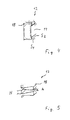
- Fig. 4 shows that in a vortex-free flow a different entry point into the respective flow channel has a different length flow line in the region of the respective channel result.
- two flow lines S 1 and S 2 are shown, wherein the flow line S 1 enters the channel further outward than the flow line S 2 .
- the flow line S 1 much longer than the flow line S 2nd So that this does not lead to an inhomogeneous distribution of the mass flow of the fluids A, B, which in turn would worsen the efficiency of the heat exchanger 10, the distances of the partitions, so the duct ceiling can be adjusted transversely to the flow direction.
- the channel thickness is advantageously chosen so that always the same pressure loss occurs for all streamlines.
- Fig. 5 shows an embodiment of the pleat package, in which the channel thickness h is correspondingly smaller where the streamlines are shorter, and in which the channel thickness H is correspondingly larger where the streamlines are longer.
- the pressure loss can also be achieved geometrically, for example, by means of installations or profiles.
- the desired channel heights h and H can be achieved, for example, by embossing the sheet material 18.
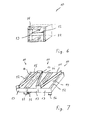
- Fig. 6 shows a schematic representation of another installation variant of the heat exchanger 10.
- the heat exchanger 10 is integrated in the embodiment shown in a muffler housing 22. In this way can be achieved with the heat exchanger 10 in addition to the heat transfer and a reduction of noise emission.
- Fig. 7 shows the modular structure of a heat transfer for large flow of several heat exchangers 10.
- the individual heat exchanger 10 are each connected in parallel.
- the partitions 15, 16 When installed in a flow channel with transverse to the flow direction channels of the pleat package 12 is obtained by the partitions 15, 16 each have a uniform flow of the channels.
- Fig. 8 shows a schematic representation of an apparatus for producing a heat exchanger 10 with the features of the invention.
- the manufacturing station 23 shown has a supply of the sheet material 18, namely a film roll 24. By means of this film roll 24, the sheet material 18 is provided for further processing.
- the film roll 24 is followed by a first heating station 25, an embossing station 26, a second heating station 27 and a folding station 28.
- the embossing station 26 has in the embodiment shown two counter-rotating rollers 29, 30.
- the sheet material is thereby provided by the film roll 24 and brought by means of the first heating station to a temperature for plastic deformation.
- This heated film is then passed between the counter-rotating rollers 29, 30 of the embossing station, wherein projections on the rollers 29, 30 produce embossments on the sheet material 18.
- the sheet material 18 thus provided with the embossings 31 is in turn heated in the second heating station for plastic deformation and laid in the folding station 28 in uniform folds.
- the fold packets 12 thus produced are cut to the desired length.
- the pleat packets 12 can then be provided with the covers 13, 17 and the central covers 14. In this way, the heat exchanger 10 are ready for installation.
- Fig. 9 shows a modular expandable heat exchanger package 32 in a perspective view.
- the heat exchanger package 32 has two similar to those in FIG. 7
- the heat exchanger package 32 has side walls 33, 34.
- flow ports 35, 36 are provided in the direction of extension to the heat exchanger 10 .
- the flow ports 35, 36 each have a partition wall 37 for separating the media A, B of the two flow systems from each other and laterally delimiting channel walls 38.
- channel sections 39, 40 are formed for the media A and B of the flow systems, respectively ,
- a plurality of heat exchanger packets 32 can be stacked one above the other, whereby the channel sections 39 and 40 correspond to one another with a suitable structure of the heat exchanger packages 32 such that two channel sections 39 and 40, a channel for connection to the respective flow system is created.
- the heat exchanger packages 32 are quasi modular expandable and at the same time easily connectable to the flow systems.
Landscapes
- Engineering & Computer Science (AREA)
- Mechanical Engineering (AREA)
- General Engineering & Computer Science (AREA)
- Chemical & Material Sciences (AREA)
- Combustion & Propulsion (AREA)
- Physics & Mathematics (AREA)
- Thermal Sciences (AREA)
- Heat-Exchange Devices With Radiators And Conduit Assemblies (AREA)
Applications Claiming Priority (1)
| Application Number | Priority Date | Filing Date | Title |
|---|---|---|---|
| DE102008011970A DE102008011970A1 (de) | 2008-02-29 | 2008-02-29 | Wärmeübertrager für fluide Medien |
Publications (2)
| Publication Number | Publication Date |
|---|---|
| EP2096396A2 true EP2096396A2 (fr) | 2009-09-02 |
| EP2096396A3 EP2096396A3 (fr) | 2009-12-02 |
Family
ID=40729094
Family Applications (1)
| Application Number | Title | Priority Date | Filing Date |
|---|---|---|---|
| EP09153885A Withdrawn EP2096396A3 (fr) | 2008-02-29 | 2009-02-27 | Caloporteur pour milieux liquides |
Country Status (2)
| Country | Link |
|---|---|
| EP (1) | EP2096396A3 (fr) |
| DE (1) | DE102008011970A1 (fr) |
Cited By (1)
| Publication number | Priority date | Publication date | Assignee | Title |
|---|---|---|---|---|
| FR3083592A1 (fr) * | 2018-07-06 | 2020-01-10 | Commissariat A L'energie Atomique Et Aux Energies Alternatives | Dispositif de recuperation d'energie entre fluides gazeux, et procede de fabrication d'un tel dispositif |
Citations (2)
| Publication number | Priority date | Publication date | Assignee | Title |
|---|---|---|---|---|
| US4042018A (en) | 1975-09-29 | 1977-08-16 | Des Champs Laboratories Incorporated | Packaging for heat exchangers |
| DE3502972A1 (de) | 1983-08-01 | 1986-07-31 | Karlheinz Dipl.-Phys. Dr. 3300 Braunschweig Raetz | Waermeaustauscher fuer die rueckgewinnung von waerme aus luft und gasen |
Family Cites Families (4)
| Publication number | Priority date | Publication date | Assignee | Title |
|---|---|---|---|---|
| GB1201715A (en) * | 1967-04-19 | 1970-08-12 | Mtu Muenchen Gmbh | Improved heat exchanger |
| SE440275B (sv) * | 1979-03-21 | 1985-07-22 | Svante Thunberg | Vermevexlare till anleggningar for ventilering av lokaler |
| US5470531A (en) * | 1992-11-03 | 1995-11-28 | Cobe Laboratories, Inc. | Exchanger and method for manufacturing the same |
| WO2008037079A1 (fr) * | 2006-09-29 | 2008-04-03 | Dpoint Technologies Inc. | Échangeur de chaleur et d'humidite plissé avec des éléments à champ d'écoulement |
-
2008
- 2008-02-29 DE DE102008011970A patent/DE102008011970A1/de not_active Withdrawn
-
2009
- 2009-02-27 EP EP09153885A patent/EP2096396A3/fr not_active Withdrawn
Patent Citations (2)
| Publication number | Priority date | Publication date | Assignee | Title |
|---|---|---|---|---|
| US4042018A (en) | 1975-09-29 | 1977-08-16 | Des Champs Laboratories Incorporated | Packaging for heat exchangers |
| DE3502972A1 (de) | 1983-08-01 | 1986-07-31 | Karlheinz Dipl.-Phys. Dr. 3300 Braunschweig Raetz | Waermeaustauscher fuer die rueckgewinnung von waerme aus luft und gasen |
Cited By (2)
| Publication number | Priority date | Publication date | Assignee | Title |
|---|---|---|---|---|
| FR3083592A1 (fr) * | 2018-07-06 | 2020-01-10 | Commissariat A L'energie Atomique Et Aux Energies Alternatives | Dispositif de recuperation d'energie entre fluides gazeux, et procede de fabrication d'un tel dispositif |
| EP3594586A1 (fr) * | 2018-07-06 | 2020-01-15 | Commissariat à l'énergie atomique et aux énergies alternatives | Dispositif de récuperation d'énergie entre fluides gazeux et procédé de fabrication d'un tel dispositif |
Also Published As
| Publication number | Publication date |
|---|---|
| DE102008011970A1 (de) | 2009-09-03 |
| EP2096396A3 (fr) | 2009-12-02 |
Similar Documents
| Publication | Publication Date | Title |
|---|---|---|
| EP2150757B1 (fr) | Échangeur de chaleur | |
| DE102012013755B4 (de) | Wärmetauscherplatteneinheit, Wärmetauscher und Verfahren zur Herstellung eines Wärmetauschers | |
| DE1601216A1 (de) | Plattenwaermeaustauscher | |
| EP3957940B1 (fr) | Module d'échangeur de chaleur à plaque à contre-courant et échangeur de chaleur à plaque à contre-courant | |
| DE202012012919U1 (de) | Rohrwärmetauscher nach dem Gegenstromprinzip mit parallelen Strömungskanälen mit vergrösserter wärmeübertragender Oberfläche | |
| DE19709601C5 (de) | Plattenwärmeübertrager | |
| DE9490288U1 (de) | Kanalwärmetauscher | |
| DE3241842A1 (de) | Plattenfoermiger waermetauscher | |
| DE2722288A1 (de) | Plattenfoermiger verdampfer | |
| DE29614186U1 (de) | Wärmetauscher, insbesondere Wäschetrocknerkondensator, und zu dessen Herstellung bestimmte Rohranordnung | |
| EP1625339B1 (fr) | Echangeur de chaleur | |
| DE202011109859U1 (de) | Flachrohr mit Turbulenzeinlage für einen Wärmetauscher, Wärmetauscher mit derartigen Flachrohren, sowie Vorrichtung zur Herstellung eines derartigen Flachrohres | |
| DE69602025T2 (de) | Verbesserter wärmetauscher | |
| DE202017102436U1 (de) | Wärmetauscher mit Mikrokanal-Struktur oder Flügelrohr-Struktur | |
| EP3786532B1 (fr) | Échangeur de chaleur de surface, système et procédé | |
| DE102008011970A1 (de) | Wärmeübertrager für fluide Medien | |
| DE10013437C1 (de) | Folienpaket für einen aus Folien aufgebauten Verdampfer | |
| EP0268831B1 (fr) | Lamelle | |
| EP1588114B1 (fr) | Échangeur de chaleur à couches à contre-courant et courant croisé | |
| DE102010063074B3 (de) | Mikrofluidisches Bauteil, Reaktor aus mehreren solchen Bauteilen und Verfahren zu deren Herstellung | |
| DE19743427B4 (de) | Wärmeübertrager | |
| DE19846346C1 (de) | Wärmeaustauscher | |
| EP3499167B1 (fr) | Dispositif de mise en température d'un espace ainsi que procédé de son fabrication | |
| DE102017217567A1 (de) | Wärmeübertrager | |
| DE10361421B4 (de) | Raumbegrenzungselement |
Legal Events
| Date | Code | Title | Description |
|---|---|---|---|
| PUAI | Public reference made under article 153(3) epc to a published international application that has entered the european phase |
Free format text: ORIGINAL CODE: 0009012 |
|
| AK | Designated contracting states |
Kind code of ref document: A2 Designated state(s): AT BE BG CH CY CZ DE DK EE ES FI FR GB GR HR HU IE IS IT LI LT LU LV MC MK MT NL NO PL PT RO SE SI SK TR |
|
| AX | Request for extension of the european patent |
Extension state: AL BA RS |
|
| PUAL | Search report despatched |
Free format text: ORIGINAL CODE: 0009013 |
|
| AK | Designated contracting states |
Kind code of ref document: A3 Designated state(s): AT BE BG CH CY CZ DE DK EE ES FI FR GB GR HR HU IE IS IT LI LT LU LV MC MK MT NL NO PL PT RO SE SI SK TR |
|
| AX | Request for extension of the european patent |
Extension state: AL BA RS |
|
| 17P | Request for examination filed |
Effective date: 20100602 |
|
| 17Q | First examination report despatched |
Effective date: 20100629 |
|
| AKX | Designation fees paid |
Designated state(s): AT BE BG CH CY CZ DE DK EE ES FI FR GB GR HR HU IE IS IT LI LT LU LV MC MK MT NL NO PL PT RO SE SI SK TR |
|
| GRAP | Despatch of communication of intention to grant a patent |
Free format text: ORIGINAL CODE: EPIDOSNIGR1 |
|
| INTG | Intention to grant announced |
Effective date: 20130328 |
|
| GRAJ | Information related to disapproval of communication of intention to grant by the applicant or resumption of examination proceedings by the epo deleted |
Free format text: ORIGINAL CODE: EPIDOSDIGR1 |
|
| GRAP | Despatch of communication of intention to grant a patent |
Free format text: ORIGINAL CODE: EPIDOSNIGR1 |
|
| INTG | Intention to grant announced |
Effective date: 20130614 |
|
| STAA | Information on the status of an ep patent application or granted ep patent |
Free format text: STATUS: THE APPLICATION IS DEEMED TO BE WITHDRAWN |
|
| 18D | Application deemed to be withdrawn |
Effective date: 20131025 |