EP3786532B1 - Échangeur de chaleur de surface, système et procédé - Google Patents
Échangeur de chaleur de surface, système et procédé Download PDFInfo
- Publication number
- EP3786532B1 EP3786532B1 EP20159462.9A EP20159462A EP3786532B1 EP 3786532 B1 EP3786532 B1 EP 3786532B1 EP 20159462 A EP20159462 A EP 20159462A EP 3786532 B1 EP3786532 B1 EP 3786532B1
- Authority
- EP
- European Patent Office
- Prior art keywords
- heat exchanger
- wing
- heat conducting
- mounting plate
- surface heat
- Prior art date
- Legal status (The legal status is an assumption and is not a legal conclusion. Google has not performed a legal analysis and makes no representation as to the accuracy of the status listed.)
- Active
Links
Images


Classifications
-
- F—MECHANICAL ENGINEERING; LIGHTING; HEATING; WEAPONS; BLASTING
- F24—HEATING; RANGES; VENTILATING
- F24D—DOMESTIC- OR SPACE-HEATING SYSTEMS, e.g. CENTRAL HEATING SYSTEMS; DOMESTIC HOT-WATER SUPPLY SYSTEMS; ELEMENTS OR COMPONENTS THEREFOR
- F24D3/00—Hot-water central heating systems
- F24D3/12—Tube and panel arrangements for ceiling, wall, or underfloor heating
- F24D3/16—Tube and panel arrangements for ceiling, wall, or underfloor heating mounted on, or adjacent to, a ceiling, wall or floor
- F24D3/165—Suspended radiant heating ceiling
-
- F—MECHANICAL ENGINEERING; LIGHTING; HEATING; WEAPONS; BLASTING
- F24—HEATING; RANGES; VENTILATING
- F24F—AIR-CONDITIONING; AIR-HUMIDIFICATION; VENTILATION; USE OF AIR CURRENTS FOR SCREENING
- F24F5/00—Air-conditioning systems or apparatus not covered by F24F1/00 or F24F3/00, e.g. using solar heat or combined with household units such as an oven or water heater
- F24F5/0089—Systems using radiation from walls or panels
- F24F5/0092—Systems using radiation from walls or panels ceilings, e.g. cool ceilings
-
- F—MECHANICAL ENGINEERING; LIGHTING; HEATING; WEAPONS; BLASTING
- F24—HEATING; RANGES; VENTILATING
- F24F—AIR-CONDITIONING; AIR-HUMIDIFICATION; VENTILATION; USE OF AIR CURRENTS FOR SCREENING
- F24F13/00—Details common to, or for air-conditioning, air-humidification, ventilation or use of air currents for screening
- F24F13/24—Means for preventing or suppressing noise
-
- F—MECHANICAL ENGINEERING; LIGHTING; HEATING; WEAPONS; BLASTING
- F24—HEATING; RANGES; VENTILATING
- F24F—AIR-CONDITIONING; AIR-HUMIDIFICATION; VENTILATION; USE OF AIR CURRENTS FOR SCREENING
- F24F2221/00—Details or features not otherwise provided for
- F24F2221/54—Heating and cooling, simultaneously or alternatively
-
- Y—GENERAL TAGGING OF NEW TECHNOLOGICAL DEVELOPMENTS; GENERAL TAGGING OF CROSS-SECTIONAL TECHNOLOGIES SPANNING OVER SEVERAL SECTIONS OF THE IPC; TECHNICAL SUBJECTS COVERED BY FORMER USPC CROSS-REFERENCE ART COLLECTIONS [XRACs] AND DIGESTS
- Y02—TECHNOLOGIES OR APPLICATIONS FOR MITIGATION OR ADAPTATION AGAINST CLIMATE CHANGE
- Y02B—CLIMATE CHANGE MITIGATION TECHNOLOGIES RELATED TO BUILDINGS, e.g. HOUSING, HOUSE APPLIANCES OR RELATED END-USER APPLICATIONS
- Y02B30/00—Energy efficient heating, ventilation or air conditioning [HVAC]
Definitions
- the present invention relates to surface heat exchangers, in particular those for air conditioning rooms. These typically comprise at least one mounting plate and a pipe system arranged thereon, which conducts a heated or cooled medium along the mounting plate.
- the mounting plate is typically secured to the mounting plate by means of at least one strip-like heat conducting plate spanning the pipe system.
- Fig. 1 shows a corresponding surface heat exchanger of the prior art, which cannot be documented in printed form.
- the illustrated surface heat exchanger 10' is of the cassette type, since the illustrated carrier plate 11' lies in a cassette 12', which is arranged on a room or space ceiling 15.
- the carrier plate 11' is glued on its underside to the inside of the cassette and is located approximately centrally.
- a pipe system 13' is arranged on the carrier plate 11' and fastened with the aid of a strip-like heat conducting plate 14'.
- the strip-like heat conducting plate 14' overlaps the pipe 13' and is glued to the carrier plate 11' on both sides.
- the surface heat exchanger shown can be modified: For example, it is known to insert insulating material into the interior 17' of the cassette, i.e. on the surface of the carrier plate 11', or to fill the entire cavity 17' with insulating material in order to ensure acoustic insulation.
- Wings according to the invention can be used particularly advantageously in open systems (for example in so-called ceiling sails), since they can ensure the convection required for the system.
- At least one blade is assigned to a heat conducting plate.
- at least or exactly two blades are assigned to a heat conducting plate, which are arranged or configured axially symmetrically to one another.
- the heat conducting plate is assigned a wing on each side, with respect to the pipe section covered by the heat conducting plate.
- Each heat conducting plate has a strip-like shape.
- the wings are provided by a separate element, in particular in the form of an attachment element which can be placed on the heat conducting plate (or an element spaced from the heat conducting plate).
- the attachment element (like the heat conducting plate) typically also has a substantially identical bead (possibly slightly enlarged) so that the attachment element can be placed on the heat conducting plate in the area of the bead.
- the attachment element only sits on a (flat) fastening section of the heat conducting plate and does not overlap the bead of the heat conducting plate.
- the blade typically protrudes from the mounting plate at a predetermined angle. If two (particularly axially symmetric) blades are assigned to the heat conducting plate, they typically protrude from the mounting plate at the same or mirror-symmetrical angle. Depending on the application, however, the two blades can also be formed or positioned at different angles.
- the wing can preferably be designed in a strip-like manner, in particular in such a way that the entire strip protrudes from the mounting plate at a homogeneous angle and this angle does not change or substantially does not change over the axial extent of the wing or the heat conducting plate.
- the mounting plate within the meaning of the present invention can be referred to in particular as the support plate described above with reference to the prior art:
- the pipe system is typically first attached to a support plate with the aid of heat conducting plates, in particular by gluing the heat conducting plate or plates to the support plate.
- the carrier plate can in particular also have a perforation, for example between the areas which are acted upon by the heat conducting plates.
- the carrier plate can be inserted later or directly (e.g. at the factory) into a holding cassette or a so-called sail and fastened there, in particular by gluing.
- the invention also encompasses the fact that the carrier plate is not (yet) inserted into a cassette or a sail at the factory, but is provided with an activatable adhesive layer on the side facing away from the pipe system.
- the intermediate product produced in this way can then be transported to an assembly site, for example, and activated on site (for example by removing a protective film over the adhesive layer) and glued into a corresponding cassette or sail.
- the invention also encompasses surface heat exchangers in which a surface of the holding cassette (or sail) provides the mounting plate.
- a surface of the holding cassette (or sail) provides the mounting plate.
- the heat-conducting plates are inserted directly into a holding cassette or a sail without a carrier plate and secured, in particular glued, there.
- the mounting plate is then provided from the inside of the corresponding cassette or sail.
- a surface heat exchanger within the meaning of the invention is therefore considered to be a structural unit.
- the surface heat exchanger already includes the support cassette or the corresponding (typically open-topped) housing as a structural unit.
- the pipe system is usually in the form of meandering pipes, consisting of straight sections and curved sections (especially of about 180°).
- a heat conducting plate is assigned to each of the straight sections of a meandering pipe.
- the straight sections of the pipe system can each be overlapped or fixed by a heat conducting plate.
- the pipe or pipe system is preferably made of copper.
- At least the straight sections of the pipe system have a D-shape in cross-section and the bent sections can, for example, have a circular shape (or a D-shape).
- other pipe cross-sections are naturally also encompassed by the invention, such as non-circular (for example, substantially triangular) or continuously circular cross-sections.
- the blade according to the invention can typically be flat, i.e., flat and closed.
- diffusers described later, can also be provided in the blade, which can ensure diffusion of the air flow, particularly in the case where air outlets for supplied air are provided in the area of the surface heat exchanger.
- the diffusers can be used in particular for turbulent air flow.
- the diffusers can be punched out, pressed out, bent out or similar from the heat conducting plate or the attachment element.
- the area between two straight pipe sections can also be referred to as a channel in this sense, as it is typically defined by two wings of a different heat conducting plate. In this sense, the mutually aligned wings of two adjacent heat conducting plates can form the channel.
- An air duct formed by vanes is typically (axially) essentially straight. For example, it may have a roughly W-shaped cross-section.
- a surface heat exchanger is typically a heat exchanger for building or room air conditioning.
- the invention also encompasses other surface heat exchangers. This is not limited to systems that utilize a heated medium: For example, heated water can be used in the pipe system via the surface heat exchanger.
- the wing is formed by the heat conducting plate (itself).
- the heat conducting plate can be rolled, bent, folded, or similarly shaped, for example in its edge regions.
- the edge or wing region can then protrude at a specific angle from the previous extension plane and/or from the extension plane of a fastening region of the heat conducting plate.
- the heat conducting plates with integrated wings can be machined in such a way that the stiffening is reduced, for example by providing material recesses (at defined intervals), in particular in the form of (thin) slots.
- Such plastic (attachment) elements are particularly cost-effective to produce.
- the plate should be arranged at a distance from the heat-conducting plate, essentially meaning that the plate should not touch it. However, even a minimal distance is sufficient for this purpose.
- such a separate element which is not designed as an attachment element, also provides, according to the invention, a wing protruding from the mounting or fastening plate.
- the separate element is arranged directly on the mounting or fastening plate, in particular glued there.
- Such a diffuser can be used in particular for turbulent air flow, in cases where this is desired.
- the diffuser (or diffusers) has a passage opening in the blade. This allows the air to be directed out of the channels formed by the blades.
- the diffuser is formed by the passage opening and, in other words, consists of a hole in the wing. To produce it, material (from the wing) can, in particular, be removed.
- the diffuser is formed in a material-neutral manner, i.e. no material is removed.
- the diffuser can, in particular, protrude from the plane of the wing with a projection. Cases in which the diffuser is pushed or pulled out of the plane, or similar, are conceivable.
- the invention is intended to encompass both cases in which no through-openings are formed in the wing as a result of the conversion into a protruding shape, as well as cases in which this does occur.
- the diffusers can be designed in a gill-like manner, for example according to Type of projection, the machining of which creates a (essentially identically shaped) passage opening.
- the wing has corresponding projections, it is particularly advantageous if these projections (and thus also the diffusers) of a wing have the same orientation.
- the openings of the wings can have any suitable shape, such as rectangular, square, round, triangular, trapezoidal or similar.
- the projections are preferably designed such that they protrude against the direction of air flow, thus allowing the air to flow particularly well through the through-openings.
- a reverse arrangement is also advantageous, in which the projections protrude in the direction of flow or are even arranged transversely to it.
- the projections are formed integrally with the wing, i.e., are essentially machined from the wing.
- the alternative namely projections made from a separate piece and arranged on the wing, is also encompassed in principle by the invention.
- a further special feature of the invention concerns the idea that the wings according to the invention provide a holding surface for an insulating element resting on them.
- the wings together with the insulation element and the mounting plate (and/or a heat conducting plate), can provide or form an air duct.
- the air duct can, as the name suggests, be used to conduct air beneath the insulation panel.
- the sash may have a bent edge to hold the insulation element.
- the invention further relates to a system comprising at least a first and a second surface heat exchanger, in particular according to one of the described claims.
- the special feature here is that the blade of the first surface heat exchanger has a different angle of attack to the mounting plate than the blade of the second surface heat exchanger.
- a system in which, depending on the application, a surface heat exchanger with different angles of attack can be used. In particular, depending on the height of the cassette or sail used, a different angle of attack may be advantageous. Depending on the application (air ducting, the best possible heat transfer, or the best possible acoustic insulation), a surface heat exchanger with a differently arranged or aligned blade or with a different angle of attack can also be used.
- the system allows in particular the storage of surface heat exchangers with different angles of attack (of the blades).
- the wings are formed by rolling, embossing, bending and/or folding and/or the application (or fastening) of the heat conducting plate and/or the separate (attachment) element is carried out by gluing and/or soldering and/or welding (in particular on the mounting plate).
- Fig. 2 Surface heat exchangers according to the invention are shown to be Fig. 2
- it is installed in the area of the ceiling 15 of a room 16 in a building in order to air-condition the room 16 from the ceiling.
- the air conditioning can serve, in particular, for heating or, alternatively, for cooling.
- cassette-type surface heat exchangers are often used.
- the actual functional components of the surface heat exchanger 10, such as the support plate or pipe system, are arranged in a holding cassette 12.
- Fig. 2 shows a surface heat exchanger system consisting of three surface heat exchangers 10a, 10b, 10c, whose holding cassettes are arranged essentially next to each other.
- the piping system is not shown.
- the pipes of all three heat exchangers 10a, 10b, and 10c can, for example, be assigned to a common inlet and/or outlet.
- Such an arrangement of surface heat exchangers 10 on a ceiling is basically known, which is why one or several of the Fig. 2
- the surface heat exchangers shown are also basically a surface heat exchanger of the state of the art according to Fig. 1 could act so that the Fig. 2 circled area is marked with the reference symbol I.
- FIG. 2 It should also be noted that this schematic representation does not show, in addition to the components of the surface heat exchanger, for example, air outlets - or corresponding output nozzles - which can be arranged in the area of the cassette 12.
- FIG. 3 A supervision that Fig. 2 elements not shown, shows Fig. 3 , according to which the carrier plate 11 is shown, but not the corresponding holding cassette 12.
- the carrier plate 11, as shown in Fig. 3 shown, can in particular be inserted into a sail or a holding cassette 12 and/or glued there.
- Fig. 3 shows in particular the meandering pipe system 13, of which Fig. 3 Two are shown as examples, also to clarify that a support plate 11 (or holding cassette 12) can have multiple pipe systems. What is not shown is that these pipe systems are typically connected or coupled to one another and each has a common water inlet and outlet.
- a typical pipe system 13 essentially comprises straight sections 17 as well as curved or bent sections 18 (wherein the curved or bent sections 18 may also comprise short, elongated sections, which in the sense of present invention, however, are not intended to be straight sections), which in particular provide a deflection of 180°.
- the straight sections 17 of the pipe system 13 are shown Fig. 3 each overlapped or secured by a so-called heat conducting plate 14, which fixes the pipe system 13 to the support plate 11.
- a wing element is assigned to the heat conducting plate 14, which in the plan view according to Fig. 3 but is not shown or visible for perspective reasons. This will be described in detail below.
- the carrier plate 11 in this embodiment represents the mounting plate.
- the carrier plate 11, or the Fig. 3 The intermediate product shown can be transported to a construction site as shown and glued into a mounting cassette. Alternatively, this can also be done at the factory. In this case, the flat surface of a mounting cassette or sail could also be referred to as a mounting plate.
- FIG. 3 typical openings 19 in the support plate 11 to improve air conditioning and possibly also acoustic improvement, which are typically arranged between the straight sections 17 of the pipe system 13.
- FIG. 4 in a perspective view the surface heat exchanger 10 according to the invention in a partially broken-off (sample) representation.
- the surface heat exchanger 10 according to the invention in a partially broken-off (sample) representation.
- only two straight sections 17 of a pipe system 13 are indicated.
- These straight Sections 17 are each attached to a support plate 11 by means of a heat conducting plate 14.
- the heat conducting plate 14 has a central bead 20 which overlaps the pipe system 13 or a straight section 17 thereof.
- the pipe system has a substantially D-shaped cross-section, particularly in the region of its straight sections 17, which is particularly well suited for contact with the carrier plate 11.
- the carrier plate 11 itself has, similar to Fig. 3 As shown, the heat-conducting surface 14 has a perforation or opening 19 between the heat-conducting surfaces and is inserted into a holding cassette 12, which is only partially shown for reasons of clarity.
- the holding cassette 12 has a holding surface 21 on which the carrier plate 11 rests flat and is glued there, for example.
- wings 22 are also assigned to the pipe system 13 or its straight sections 17.
- the wings 22 are in the embodiment according to Fig. 4 provided by separate attachment elements 23, which sit on the heat-conducting plate 14 in the region of the bead 20 and are glued there, for example.
- the attachment elements can also have beads that are almost identical to the beads 20 of the heat-conducting plate, but possibly have a slightly larger radius.
- Fig. 4 also shows that these attachment elements 23 are essentially formed from identical blanks as the heat conducting plates 14. Accordingly, they can in particular consist of the same material, for example aluminum (or alternatively steel).
- each straight section 17 or each heat-conducting plate 14 is assigned to each straight section 17 or each heat-conducting plate 14.
- These pairs 22a, 22b, 22c, and 22d each form an air duct 24 above the straight section 17 of the pipe system 13 or above the heat-conducting plate 14.
- the duct 24, like the wings 22, extends essentially in the axial direction A of the pipe system or the heat-conducting plates 14.
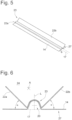
- Fig. 5 shows a corresponding heat conducting plate 14 and attachment element 23, according to Fig. 4 , but in a unique position with the dashed pipe system 13 and the straight section 17.
- Fig. 4 merely represents an exemplary section of a surface heat exchanger 10 with two exemplary straight sections 17. In practice, however, there may of course be many more straight sections.
- Fig. 6 shows a cross-sectional view of the Fig. 5 with the dashed section 17 of the pipe system 13, which has a D-shaped cross-section.
- the angle ⁇ is typically between 0° and 90°, for example between 30° and 60°, preferably between 40° and 50°. in particular of approximately 45°.
- the two angles designated by ⁇ can also be of different sizes (cf. comments on Fig. 13 ).
- Fig. 6 thus reveals an essentially axially symmetric cross-section to the longitudinal axis L; at different angles ⁇ the cross-section would of course be asymmetric.
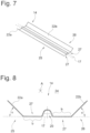
- the wings 22a, 22b are not provided by a separate attachment element, but are formed by the heat conducting plate 14 itself.
- the heat conducting plate 14 is therefore, in contrast to the one from the example according to the Figs. 5 and 6 , is not formed continuously flat on both sides of the bead 20, but bends in its edge regions 25 and 26 to form said wings 22.
- the wings 22, which in this embodiment are part of the heat conducting plate 14, form an angle of attack ⁇ (which in the embodiment according to the Figs. 7 and 8 the one according to the Figs. 5 and 6 corresponds to approximately 45°).
- the angle is not formed relative to the heat conducting plate, but relative to a Fig. 8 not shown mounting plate, which can be provided for example by the carrier plate or the holding plate of a holding cassette or a sail (in Fig. 8 the corresponding level is indicated by a dashed line).
- the cross-sectional view according to Fig. 8 clarifies that in this embodiment not according to the invention, the wings 22 do not directly adjoin a bead, but the heat conducting plate 14 forms flat holding areas 27 between the wings 22 and the bead 20, which, according to their width b, for example, correspond approximately to the holding areas 27 according to the embodiment according to the Figs. 5 and 6 or can be somewhat narrower (whereby these areas 27 according to the embodiment according to Figs. 7 and 8 then merge into the wings 22, while in the embodiment according to the Figs. 5 and 6 is not the case at the moment).
- the heat conducting plates 14 can also in this case be made of aluminum, for example, in particular of black painted aluminum, which can further improve the thermal conductivity.
- the heat conducting plates (and/or attachment elements) of the other embodiments can also be made of painted aluminum or of bare aluminum, in particular also the present embodiment.
- Double-sided adhesive tape could also be provided on the underside of the heat-conducting plate, for example, to advantageously attach it to a mounting plate. This also applies to the heat-conducting plates of the other embodiments, and possibly even to the attachment elements.
- the wings can be (permanently) connected to the pipe and/or the heat-conducting sheet in another way, for example by soldering, welding, gluing or similar.
- Both embodiments form between their flights according to the Fig. 6 and 8 one air duct 24 each.
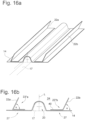
- the embodiment according to the Figs. 9 and 10 has more steeply pitched or inclined wings 22a and 22b, which thus form a larger angle of attack ⁇ .
- this angle ⁇ also lies in the range between 0° and 90°, it exceeds an angle of 45° and can, for example, be in the range between 45° and 90°.
- angles can also be greater than 90°, especially for air guidance.
- Fig. 9 The second, possibly even more significant, difference is particularly evident in Fig. 9 can be seen, and consists in that the wings 22 are provided with diffusers 28.
- the diffusers 28 consist merely of through-openings or perforations 29 in the wings 22.
- these openings 29 have, by way of example, a rectangular shape, but can also have any other suitable shape.
- the diffusers 28 are all identically oriented and aligned (although this does not necessarily have to be the case, depending on the application).
- the diffusers 28 enable a more turbulent air flow in the channel 24.
- the air from the channel 24 can pass through such a perforation 29 to the outer side 30 of the blades 22 (where the corresponding blade can then form a separate channel with a corresponding counter-blade of another heat conducting plate 14).
- FIG. 9 only exemplary designated 31 and essentially comprises the frame of two perforations, thus being more than twice as large as the other perforation according to Fig. 9 .
- FIG. 11 and 12 Another example is shown in the Figs. 11 and 12 .
- the embodiment essentially corresponds to that according to the Figs. 5 and 6 (to whose statements reference is made).
- the angle of attack ⁇ of the blades 22 in this embodiment is smaller than that in the embodiments according to the Fig. 5 to 8
- the angle ⁇ also ranges between 0° and 90°, in this example it is less than 45° and thus lies between 0° and 45°. This also illustrates that the angle of attack can vary depending on the application.
- the second difference (in contrast to the Figs. 5 and 6 ) also consists in this embodiment in that diffusers 28' are provided in the wings 22.
- the diffusers 28' according to Figs. 11 and 12 differ from the diffusers 28 according to the embodiment according to Figs. 9 and 10 essentially in that the diffuser 28' comprises, in addition to a recess 29', also a (material) projection 32.
- the diffuser 28' is thus essentially gill-like and the projection gill-valve-like.
- the difference between the diffuser 28' and the diffuser 28 is that the diffuser 28' is material-neutral, while the diffuser 28 (compared to the original state of the wing 22, but also to the diffuser 28') has less material (this was punched out for the recess or perforation 29, for example, or similar).
- the projection 32 can have substantially the same shape as the recess 29', since the machining of the projection 32 out of the wing 22 takes place precisely by emerging from the material plane of the wing 22, forming the recess 29'.
- a further special feature of the illustrated embodiment is that the projection 32 protrudes counter to the axial direction A (and thus the flow direction of the air to be guided). In this way, the air flowing in the axial direction A can be guided particularly well through the recesses or perforations 29' and thus out of the area of the air duct 24 to the outer side 30.
- the arrangement and orientation of the projections and/or perforations can be arbitrary, depending on the application, for example diagonally or similar.
- a second aspect of these vanes concerns improved air guidance, especially if air outlet nozzles are provided in the area of the surface heat exchanger.
- the vanes can, in particular, form air channels to direct or guide the air.
- turbulent air flow may also be desired, for which purpose diffusers are provided.
- plastic wings may be sufficient for this purpose. Even if this is not explicitly shown in the exemplary embodiments, an attachment element 23, as shown in the exemplary embodiment according to the Figs. 5 and 6 As shown, it can be made of plastic. This will be particularly useful in applications where the goal is not necessarily to improve thermal conductivity, but rather to influence the acoustics.
- FIG. 13 shows an embodiment which is essentially the same as that of Figs. 5 and 6 corresponds, wherein in addition to the first attachment element 23, a second attachment element 23' is provided.
- This second attachment element 23' is placed, for example, on the first attachment element 23 and fastened there, for example in the area of the bead 20.
- the wings 22a' and 22b' can be at different angles than the wings 22a and 22b, respectively.
- Fig. 13 shows a further special feature, which should be considered as disclosed not only in the case of two attachment elements:
- the first attachment element 23 has (two) flat contact areas 27', which should clarify that the attachment of an attachment element does not have to be carried out via the bead, but also via corresponding support areas (as for example from Fig. 8 also known from heat conducting plates themselves) is possible.
- Fig. 13 It should be noted that the illustrated embodiment with two (or more) wings (22a and 22a', or 22b and 22b') arranged substantially one above the other is not only intended to be disclosed for the version in which the heat-conducting plate has no wings. Rather, this idea (of several wings arranged substantially one above the other) is also intended to be disclosed for the embodiments in which the heat-conducting plate itself forms at least one wing.
- Fig. 13 In the embodiment according to Fig. 13 thus, in summary, four blades are disclosed. Of course, more blades (for example, 6 or 8 or even more) can be arranged on one pipe section.
- FIG. 14a to 14d This is how the Fig. 14a and 14b Views of non-inventive embodiments, for example according to Fig. 8
- Fig. 8 The difference compared to Fig. 8
- this essentially consists in the fact that the wings 22 each have a bent edge 34 in the wing 22, so that the wing 22 as a whole forms a holding surface for a merely in Fig. 14a indicated insulating element 35.
- the holding surface is provided by holding sections 36 of the respective wing 22, which are formed by the part of the wing 22 which is located beyond (or outside) the bent edge 34 or fold.
- the (air) channel formed by the wing elements 22 can be limited upwards by the insulating element 35. This can be a further, additional, positive effect of such an embodiment with a holding surface for an insulating element.
- the angle of attack ⁇ is, for example, approximately 90° (this can, by the way, apply to all embodiments of the application) and the bending angle ⁇ is also.
- Fig. 14b shows that the angle of attack ⁇ and the bend angle ⁇ do not have to be the same.
- the bend angle ⁇ greater than 90°, and more advantageously even greater than 180°.
- the idea of bending edges cannot, of course, be considered only at an angle ⁇ of 90°.
- Fig. 14c and 14d essentially correspond to a view roughly according to Fig. 6 , thus, in contrast to the Fig. 14a and 14b not from a heat-conducting plate with integrated wings, but from a heat-conducting plate 27 on which an attachment element 23 is provided.
- bent edges 34 are provided to form support surfaces.
- Fig. 14c This particularly illustrates that the bending angles ⁇ do not have to be identical in one embodiment.
- Fig. 14 It should be noted that the holding surface for holding the insulation material 35 does not, of course, have to consist only of horizontal holding sections 36, as in Fig. 14a and 14c Rather, sections 36 (as for example in Fig. 14b and 14d ) - depending on the shape of the insulation material - can also have other orientations.
- FIG. 15a and 15b A further embodiment according to the invention is shown in the Figures 15a and 15b .
- FIG. 15a and 15b are roughly in line with the views of, for example, Figs. 5 and 6 comparable.
- Fig. 15a under dashed indication of a straight pipe section 17, a heat conducting plate 14 overlapping this and a wing 22 arranged thereon.
- This wing 22 is shown Fig. 15b in this embodiment from a separate Attachment element 23" provided.
- the attachment element 23" is not designed such that it overlaps the bead 20 of the heat-conducting plate 14. Rather, it is arranged next to or to the side of the bead 20, in particular in or on a (flat) holding area 27 of the heat-conducting plate 14.
- This embodiment thus particularly illustrates that the separate element 23" providing the wing 22 can be designed as an attachment element for the heat conducting plate 14, but does not necessarily have to cover its bead 20.
- FIG. 15b an air duct 24 is indicated, which extends between the wing 22 and either another wing not shown (e.g. another heat conducting plate), or between the wing 22 and the bead 20.
- another wing not shown e.g. another heat conducting plate
- different air ducts 24 suitable for the application can be provided in this way.
- This embodiment also improves the heat transfer between the pipe and the environment thanks to the wings.
- the attachment element 23"b to the right of the bead is equipped with a wing 22b which does not protrude at a right angle from the heat conducting plate 14, but at an angle ⁇ between 0 and 90 degrees, for example of approximately 45 degrees.
- the embodiment should be designed according to the Fig. 16a and 16b make it clear that an attachment element, as shown in Fig. 15a and 15b shown, can also be fastened, in particular glued, to the heat conducting plate 14 on both sides of the bead 20.
- Fig. 16a and 16b that the two wings 22a and 22b can protrude "in the same direction". If the If wing 22b has an angle of attack ⁇ , then wing 22a has an angle of attack of 180 degrees - ⁇ . Therefore, Fig. 16b the inner angle of the attachment element 23"a is designated ⁇ , since this corresponds to the actual angle of attack or outer angle of the other attachment element 23"b.
- the invention also encompasses an embodiment in which the angles of attack of the two attachment elements are mirror-symmetrical (i.e., both have the value ⁇ ) or in which they each assume completely different angles of attack. All of these are intended to be encompassed by the invention.
- FIG. 17a A schematic, fragmentary top view of part of a surface heat exchanger consisting of a conventional carrier plate 11 with two heat conducting plates 14 mounted or glued thereon.
- a carrier plate 11 can, for example, be inserted into a sail or a holding cassette or glued therein.
- the plate 11 can also directly represent the inside of a holding cassette.
- the wings 22 in this example are not provided by a heat conducting plate 14. Rather, separate elements 23′′′ are provided, which provide the wings 22.
- a second separate element 23′′′b is shown, with, for example, an acute angle of attack ⁇ .
- This element 23′′′b is also arranged at a distance from the heat conducting plate closest to it.
- Both elements 23′′′ are fixed to the carrier plate 11, in particular glued there (preferably over the entire surface with their contact area).
Landscapes
- Engineering & Computer Science (AREA)
- Chemical & Material Sciences (AREA)
- Combustion & Propulsion (AREA)
- Mechanical Engineering (AREA)
- General Engineering & Computer Science (AREA)
- Physics & Mathematics (AREA)
- Thermal Sciences (AREA)
- Life Sciences & Earth Sciences (AREA)
- Sustainable Development (AREA)
- Heat-Exchange Devices With Radiators And Conduit Assemblies (AREA)
Claims (13)
- Échangeur de chaleur de surface (10), en particulier pour la climatisation de locaux (16), comprenant une plaque de montage (11, 12) et un système de tuyaux (13) pour guider un milieu le long de la plaque de montage (11, 12), dans lequel le système de tuyaux (13) est fixé à la plaque de montage (11) à l'aide de plaques thermoconductrices (14) en forme de lames chevauchant le système de tuyaux (13) de manière fermée des deux côtés, caractérisé en ce qu'au moins une ailette (22) qui fait saillie de la plaque de montage (11, 12) est associée respectivement aux plaques thermoconductrices (14) et conçue par un élément (23, 23', 23'', 23‴) distinct par rapport à la plaque thermoconductrice et à la plaque de montage (11, 12).
- Échangeur de chaleur de surface (10) selon la revendication 1, caractérisé en ce que les plaques thermoconductrices (14) et l'élément distinct (23) sont composés du même matériau, en particulier en aluminium.
- Échangeur de chaleur de surface (10) selon la revendication 1, caractérisé en ce que l'élément distinct (23, 23', 23'', 23‴) est composé de matière plastique.
- Échangeur de chaleur de surface (10) selon une des revendications précédentes, caractérisé en ce que l'ailette (22) présente au moins un diffuseur (28, 28') qui comprend en particulier une ouverture de passage d'ailette (29, 29') ou est formé par celle-ci.
- Échangeur de chaleur de surface (10) selon la revendication 4, caractérisé en ce que le diffuseur (28') présente une saillie (32), qui dépasse en particulier du plan d'ailette et qui de préférence coïncide sensiblement avec une ouverture de passage d'ailette (29') du diffuseur (28').
- Échangeur de chaleur de surface (10) selon une des revendications précédentes, caractérisé en ce que l'échangeur de chaleur de surface (10) présente plusieurs ailettes (22, 22') disposées sensiblement les unes au-dessus des autres, de préférence des deux côtés, respectivement une paire.
- Échangeur de chaleur de surface (10) selon une des revendications précédentes, caractérisé en ce que l'élément distinct est conçu sous la forme d'un élément de fixation (23, 23', 23").
- Échangeur de chaleur de surface (10) selon la revendication 7, caractérisé en ce que l'élément de fixation (23) se fixe, en particulier exclusivement, au niveau d'une nervure (20) d'une plaque thermoconductrice (14) sur cette dernière.
- Échangeur de chaleur de surface (10) selon la revendication 7, caractérisé en ce que l'élément de fixation (23', 23'') se fixe, en particulier exclusivement, au niveau d'une zone d'appui (27), en particulier plane, d'une plaque thermoconductrice (14) sur cette dernière.
- Échangeur de chaleur de surface (10) selon une des revendications 1 à 6, caractérisé en ce que l'élément distinct (23‴) est distant d'une plaque thermoconductrice (14).
- Système comprenant au moins un premier et un second échangeurs de chaleur de surface (10) selon une des revendications 1 à 10, dans lequel au moins une des ailettes (22) du premier échangeur de chaleur de surfaces présente un autre angle d'incidence (α, β, γ) par rapport à la plaque de montage (11, 12) qu'au moins une des ailettes (22) du second échangeur de chaleur de surfaces (10).
- Procédé destiné à guider de l'air et/ou transmettre de la chaleur le long d'un échangeur de chaleur de surface (10) selon une des revendications 1 à 10 et/ou à isoler de manière acoustique celui-ci, dans lequel un système de tuyaux (13), pour guider un milieu, est fixé à une plaque de montage (11) à l'aide de plaques thermoconductrices (14) chevauchant le système de tuyaux (13) de manière fermée des deux côtés, dans lequel au moins une ailette (22) qui fait saillie de la plaque de montage (11, 12) est associée respectivement aux plaques thermoconductrices (14) et guide l'air et/ou transmet la chaleur et/ou isole de manière acoustique.
- Procédé destiné à fabriquer un échangeur de chaleur de surface (10) selon une des revendications 1 à 10 en utilisant une plaque de montage (11, 12) et un système de tuyaux (13) pour guider un milieu le long de la plaque de montage (11, 12), dans lequel le système de tuyaux (13) est fixé à la plaque de montage (11) à l'aide de plaques thermoconductrices (14) chevauchant le système de tuyaux (13) de manière fermée des deux côtés, et dans lequel au moins une ailette (22) qui fait saillie de la plaque de montage (11, 12) est associée respectivement aux plaques thermoconductrices (14).
Applications Claiming Priority (1)
| Application Number | Priority Date | Filing Date | Title |
|---|---|---|---|
| DE102019123117.5A DE102019123117A1 (de) | 2019-08-28 | 2019-08-28 | Flächenwärmetauscher, System und Verfahren |
Publications (2)
| Publication Number | Publication Date |
|---|---|
| EP3786532A1 EP3786532A1 (fr) | 2021-03-03 |
| EP3786532B1 true EP3786532B1 (fr) | 2025-05-28 |
Family
ID=69740189
Family Applications (1)
| Application Number | Title | Priority Date | Filing Date |
|---|---|---|---|
| EP20159462.9A Active EP3786532B1 (fr) | 2019-08-28 | 2020-02-26 | Échangeur de chaleur de surface, système et procédé |
Country Status (2)
| Country | Link |
|---|---|
| EP (1) | EP3786532B1 (fr) |
| DE (1) | DE102019123117A1 (fr) |
Families Citing this family (2)
| Publication number | Priority date | Publication date | Assignee | Title |
|---|---|---|---|---|
| EP4220021B1 (fr) * | 2022-01-27 | 2025-08-06 | Schmöle GmbH | Déflecteur de chaleur et procédé de fabrication d'un tel déflecteur |
| DE102022121668A1 (de) * | 2022-08-26 | 2024-02-29 | Schmöle GmbH | Wärmeleitblech, Wärmetauscher und Verfahren zur Herstellung von Wärmeleitblechen |
Family Cites Families (9)
| Publication number | Priority date | Publication date | Assignee | Title |
|---|---|---|---|---|
| BE571490A (fr) * | 1900-01-01 | |||
| US3379241A (en) * | 1965-04-15 | 1968-04-23 | Gen Motors Corp | Refrigerator condenser apparatus with funnel shaped flue |
| FR2085165B1 (fr) * | 1969-12-05 | 1973-12-21 | Atar | |
| DE4031062A1 (de) * | 1990-10-02 | 1992-04-09 | Koester Helmut | Deckentraegerprofilschiene fuer heiz- und kuehlzwecke |
| DE9412349U1 (de) * | 1994-07-30 | 1994-10-06 | H. Krantz-Tkt Gmbh, 51465 Bergisch Gladbach | Kühldecke |
| US5957194A (en) * | 1996-06-27 | 1999-09-28 | Advanced Thermal Solutions, Inc. | Plate fin heat exchanger having fluid control means |
| DE202009017997U1 (de) * | 2009-01-13 | 2010-11-04 | Frenger Systemen BV Heiz- und Kühltechnik GmbH | Strahlflächenaufbau |
| DE202010010564U1 (de) * | 2010-07-23 | 2010-10-14 | Gib Gesellschaft Für Innovative Bautechnologie Mbh | Heiz- oder Kühlelement für einen Deckenaufbau |
| DE102017130081A1 (de) * | 2017-12-15 | 2019-06-19 | Krantz Gmbh | Vorrichtung zur Temperierung eines Raumes |
-
2019
- 2019-08-28 DE DE102019123117.5A patent/DE102019123117A1/de active Pending
-
2020
- 2020-02-26 EP EP20159462.9A patent/EP3786532B1/fr active Active
Also Published As
| Publication number | Publication date |
|---|---|
| EP3786532A1 (fr) | 2021-03-03 |
| DE102019123117A1 (de) | 2021-03-04 |
Similar Documents
| Publication | Publication Date | Title |
|---|---|---|
| EP0176729A1 (fr) | Echangeur de chaleur, ainsi que procédé et dispositif pour sa fabrication | |
| EP3499145B1 (fr) | Arrangement d'un dispositif de mise en température d'un espace sous un plafond | |
| EP1204816A1 (fr) | Element melangeur pour un fluide guide dans un tuyau | |
| EP0566899B1 (fr) | Echangeur de chaleur, notamment évaporateur | |
| WO2013139507A1 (fr) | Échangeur de chaleur, procédé de production correspondant et divers systèmes avec un tel échangeur de chaleur | |
| EP3786532B1 (fr) | Échangeur de chaleur de surface, système et procédé | |
| DE2306559A1 (de) | Konvektor und herstellungsverfahren | |
| DE29614186U1 (de) | Wärmetauscher, insbesondere Wäschetrocknerkondensator, und zu dessen Herstellung bestimmte Rohranordnung | |
| EP1640684A1 (fr) | echangeur de chaleur à tubes plats et ailettes ondulées | |
| DE202017102436U1 (de) | Wärmetauscher mit Mikrokanal-Struktur oder Flügelrohr-Struktur | |
| EP2167895B1 (fr) | Échangeur de chaleur | |
| DE102006002932B4 (de) | Wärmetauscher und Herstellungsverfahren für Wärmetauscher | |
| EP0225533B1 (fr) | Echangeur de chaleur plan | |
| DE10241635A1 (de) | Flachrohr-Wärmeübertrager sowie Herstellungsverfahren hierfür | |
| EP4375604A1 (fr) | Échangeur de chaleur à ailettes, son procédé de fabrication et système | |
| DE102014226713A1 (de) | Deckenradiatorprofil | |
| DE2156239B2 (de) | Konvektor mit einer Anzahl von parallelen, im wesentlichen ebenen Blechflanschen | |
| EP4538602A1 (fr) | Dispositif de thermorégulation d'une pièce | |
| DE102010053478B4 (de) | Wärmeübertrager und Herstellungsverfahren für Wärmeübertrager | |
| CH720433B1 (de) | Wärmetauscher und Verfahren zu dessen Herstellung | |
| DE102017130090A1 (de) | Vorrichtung sowie Verfahren zum Temperieren eines Raumes | |
| AT521396B1 (de) | Klimakanal | |
| DE8628175U1 (de) | Lamelle | |
| EP4400773A1 (fr) | Echangeur de chaleur et procédé pour son utilisation | |
| DE202023001602U1 (de) | Lamellen-Wärmeübertrager |
Legal Events
| Date | Code | Title | Description |
|---|---|---|---|
| PUAI | Public reference made under article 153(3) epc to a published international application that has entered the european phase |
Free format text: ORIGINAL CODE: 0009012 |
|
| STAA | Information on the status of an ep patent application or granted ep patent |
Free format text: STATUS: THE APPLICATION HAS BEEN PUBLISHED |
|
| AK | Designated contracting states |
Kind code of ref document: A1 Designated state(s): AL AT BE BG CH CY CZ DE DK EE ES FI FR GB GR HR HU IE IS IT LI LT LU LV MC MK MT NL NO PL PT RO RS SE SI SK SM TR |
|
| AX | Request for extension of the european patent |
Extension state: BA ME |
|
| STAA | Information on the status of an ep patent application or granted ep patent |
Free format text: STATUS: REQUEST FOR EXAMINATION WAS MADE |
|
| 17P | Request for examination filed |
Effective date: 20210705 |
|
| RBV | Designated contracting states (corrected) |
Designated state(s): AL AT BE BG CH CY CZ DE DK EE ES FI FR GB GR HR HU IE IS IT LI LT LU LV MC MK MT NL NO PL PT RO RS SE SI SK SM TR |
|
| STAA | Information on the status of an ep patent application or granted ep patent |
Free format text: STATUS: EXAMINATION IS IN PROGRESS |
|
| 17Q | First examination report despatched |
Effective date: 20230124 |
|
| GRAP | Despatch of communication of intention to grant a patent |
Free format text: ORIGINAL CODE: EPIDOSNIGR1 |
|
| STAA | Information on the status of an ep patent application or granted ep patent |
Free format text: STATUS: GRANT OF PATENT IS INTENDED |
|
| GRAJ | Information related to disapproval of communication of intention to grant by the applicant or resumption of examination proceedings by the epo deleted |
Free format text: ORIGINAL CODE: EPIDOSDIGR1 |
|
| STAA | Information on the status of an ep patent application or granted ep patent |
Free format text: STATUS: EXAMINATION IS IN PROGRESS |
|
| INTG | Intention to grant announced |
Effective date: 20241128 |
|
| GRAP | Despatch of communication of intention to grant a patent |
Free format text: ORIGINAL CODE: EPIDOSNIGR1 |
|
| STAA | Information on the status of an ep patent application or granted ep patent |
Free format text: STATUS: GRANT OF PATENT IS INTENDED |
|
| INTC | Intention to grant announced (deleted) | ||
| INTG | Intention to grant announced |
Effective date: 20250103 |
|
| GRAS | Grant fee paid |
Free format text: ORIGINAL CODE: EPIDOSNIGR3 |
|
| GRAA | (expected) grant |
Free format text: ORIGINAL CODE: 0009210 |
|
| STAA | Information on the status of an ep patent application or granted ep patent |
Free format text: STATUS: THE PATENT HAS BEEN GRANTED |
|
| AK | Designated contracting states |
Kind code of ref document: B1 Designated state(s): AL AT BE BG CH CY CZ DE DK EE ES FI FR GB GR HR HU IE IS IT LI LT LU LV MC MK MT NL NO PL PT RO RS SE SI SK SM TR |
|
| REG | Reference to a national code |
Ref country code: GB Ref legal event code: FG4D Free format text: NOT ENGLISH |
|
| REG | Reference to a national code |
Ref country code: CH Ref legal event code: EP |
|
| REG | Reference to a national code |
Ref country code: IE Ref legal event code: FG4D Free format text: LANGUAGE OF EP DOCUMENT: GERMAN Ref country code: DE Ref legal event code: R096 Ref document number: 502020011119 Country of ref document: DE |
|
| REG | Reference to a national code |
Ref country code: NL Ref legal event code: MP Effective date: 20250528 |
|
| PG25 | Lapsed in a contracting state [announced via postgrant information from national office to epo] |
Ref country code: FI Free format text: LAPSE BECAUSE OF FAILURE TO SUBMIT A TRANSLATION OF THE DESCRIPTION OR TO PAY THE FEE WITHIN THE PRESCRIBED TIME-LIMIT Effective date: 20250528 Ref country code: ES Free format text: LAPSE BECAUSE OF FAILURE TO SUBMIT A TRANSLATION OF THE DESCRIPTION OR TO PAY THE FEE WITHIN THE PRESCRIBED TIME-LIMIT Effective date: 20250528 |
|
| REG | Reference to a national code |
Ref country code: LT Ref legal event code: MG9D |
|
| PG25 | Lapsed in a contracting state [announced via postgrant information from national office to epo] |
Ref country code: NO Free format text: LAPSE BECAUSE OF FAILURE TO SUBMIT A TRANSLATION OF THE DESCRIPTION OR TO PAY THE FEE WITHIN THE PRESCRIBED TIME-LIMIT Effective date: 20250828 Ref country code: GR Free format text: LAPSE BECAUSE OF FAILURE TO SUBMIT A TRANSLATION OF THE DESCRIPTION OR TO PAY THE FEE WITHIN THE PRESCRIBED TIME-LIMIT Effective date: 20250829 |
|
| PG25 | Lapsed in a contracting state [announced via postgrant information from national office to epo] |
Ref country code: PL Free format text: LAPSE BECAUSE OF FAILURE TO SUBMIT A TRANSLATION OF THE DESCRIPTION OR TO PAY THE FEE WITHIN THE PRESCRIBED TIME-LIMIT Effective date: 20250528 Ref country code: NL Free format text: LAPSE BECAUSE OF FAILURE TO SUBMIT A TRANSLATION OF THE DESCRIPTION OR TO PAY THE FEE WITHIN THE PRESCRIBED TIME-LIMIT Effective date: 20250528 |
|
| PG25 | Lapsed in a contracting state [announced via postgrant information from national office to epo] |
Ref country code: BG Free format text: LAPSE BECAUSE OF FAILURE TO SUBMIT A TRANSLATION OF THE DESCRIPTION OR TO PAY THE FEE WITHIN THE PRESCRIBED TIME-LIMIT Effective date: 20250528 |
|
| PG25 | Lapsed in a contracting state [announced via postgrant information from national office to epo] |
Ref country code: HR Free format text: LAPSE BECAUSE OF FAILURE TO SUBMIT A TRANSLATION OF THE DESCRIPTION OR TO PAY THE FEE WITHIN THE PRESCRIBED TIME-LIMIT Effective date: 20250528 |
|
| PG25 | Lapsed in a contracting state [announced via postgrant information from national office to epo] |
Ref country code: RS Free format text: LAPSE BECAUSE OF FAILURE TO SUBMIT A TRANSLATION OF THE DESCRIPTION OR TO PAY THE FEE WITHIN THE PRESCRIBED TIME-LIMIT Effective date: 20250828 |
|
| PG25 | Lapsed in a contracting state [announced via postgrant information from national office to epo] |
Ref country code: IS Free format text: LAPSE BECAUSE OF FAILURE TO SUBMIT A TRANSLATION OF THE DESCRIPTION OR TO PAY THE FEE WITHIN THE PRESCRIBED TIME-LIMIT Effective date: 20250928 |
|
| PG25 | Lapsed in a contracting state [announced via postgrant information from national office to epo] |
Ref country code: LV Free format text: LAPSE BECAUSE OF FAILURE TO SUBMIT A TRANSLATION OF THE DESCRIPTION OR TO PAY THE FEE WITHIN THE PRESCRIBED TIME-LIMIT Effective date: 20250528 |
|
| PG25 | Lapsed in a contracting state [announced via postgrant information from national office to epo] |
Ref country code: SM Free format text: LAPSE BECAUSE OF FAILURE TO SUBMIT A TRANSLATION OF THE DESCRIPTION OR TO PAY THE FEE WITHIN THE PRESCRIBED TIME-LIMIT Effective date: 20250528 Ref country code: DK Free format text: LAPSE BECAUSE OF FAILURE TO SUBMIT A TRANSLATION OF THE DESCRIPTION OR TO PAY THE FEE WITHIN THE PRESCRIBED TIME-LIMIT Effective date: 20250528 |
|
| PG25 | Lapsed in a contracting state [announced via postgrant information from national office to epo] |
Ref country code: CZ Free format text: LAPSE BECAUSE OF FAILURE TO SUBMIT A TRANSLATION OF THE DESCRIPTION OR TO PAY THE FEE WITHIN THE PRESCRIBED TIME-LIMIT Effective date: 20250528 |
|
| PG25 | Lapsed in a contracting state [announced via postgrant information from national office to epo] |
Ref country code: EE Free format text: LAPSE BECAUSE OF FAILURE TO SUBMIT A TRANSLATION OF THE DESCRIPTION OR TO PAY THE FEE WITHIN THE PRESCRIBED TIME-LIMIT Effective date: 20250528 |
|
| PG25 | Lapsed in a contracting state [announced via postgrant information from national office to epo] |
Ref country code: SK Free format text: LAPSE BECAUSE OF FAILURE TO SUBMIT A TRANSLATION OF THE DESCRIPTION OR TO PAY THE FEE WITHIN THE PRESCRIBED TIME-LIMIT Effective date: 20250528 |
|
| PG25 | Lapsed in a contracting state [announced via postgrant information from national office to epo] |
Ref country code: IT Free format text: LAPSE BECAUSE OF FAILURE TO SUBMIT A TRANSLATION OF THE DESCRIPTION OR TO PAY THE FEE WITHIN THE PRESCRIBED TIME-LIMIT Effective date: 20250528 |
|
| REG | Reference to a national code |
Ref country code: DE Ref legal event code: R097 Ref document number: 502020011119 Country of ref document: DE |
|
| PLBE | No opposition filed within time limit |
Free format text: ORIGINAL CODE: 0009261 |
|
| STAA | Information on the status of an ep patent application or granted ep patent |
Free format text: STATUS: NO OPPOSITION FILED WITHIN TIME LIMIT |
|
| REG | Reference to a national code |
Ref country code: CH Ref legal event code: L10 Free format text: ST27 STATUS EVENT CODE: U-0-0-L10-L00 (AS PROVIDED BY THE NATIONAL OFFICE) Effective date: 20260409 |
|
| PGFP | Annual fee paid to national office [announced via postgrant information from national office to epo] |
Ref country code: DE Payment date: 20260225 Year of fee payment: 7 |