EP2096434B1 - Vorrichtung zum Feststellen der Verschlechterung von einem Schmieröl - Google Patents
Vorrichtung zum Feststellen der Verschlechterung von einem Schmieröl Download PDFInfo
- Publication number
- EP2096434B1 EP2096434B1 EP08171505.4A EP08171505A EP2096434B1 EP 2096434 B1 EP2096434 B1 EP 2096434B1 EP 08171505 A EP08171505 A EP 08171505A EP 2096434 B1 EP2096434 B1 EP 2096434B1
- Authority
- EP
- European Patent Office
- Prior art keywords
- oil
- electric
- current
- pump
- revolution
- Prior art date
- Legal status (The legal status is an assumption and is not a legal conclusion. Google has not performed a legal analysis and makes no representation as to the accuracy of the status listed.)
- Not-in-force
Links
- 238000006731 degradation reaction Methods 0.000 title claims description 58
- 230000015556 catabolic process Effects 0.000 title claims description 24
- 239000010687 lubricating oil Substances 0.000 title 1
- 238000005259 measurement Methods 0.000 claims description 34
- 239000003921 oil Substances 0.000 description 118
- 239000010705 motor oil Substances 0.000 description 14
- 230000005540 biological transmission Effects 0.000 description 13
- 238000001514 detection method Methods 0.000 description 8
- 238000010586 diagram Methods 0.000 description 7
- 238000000034 method Methods 0.000 description 6
- 230000000704 physical effect Effects 0.000 description 3
- 230000000694 effects Effects 0.000 description 2
- 230000010354 integration Effects 0.000 description 2
- 230000033001 locomotion Effects 0.000 description 2
- 238000005461 lubrication Methods 0.000 description 2
- 230000000593 degrading effect Effects 0.000 description 1
- 239000004973 liquid crystal related substance Substances 0.000 description 1
Images

Classifications
-
- G—PHYSICS
- G01—MEASURING; TESTING
- G01N—INVESTIGATING OR ANALYSING MATERIALS BY DETERMINING THEIR CHEMICAL OR PHYSICAL PROPERTIES
- G01N33/00—Investigating or analysing materials by specific methods not covered by groups G01N1/00 - G01N31/00
- G01N33/26—Oils; Viscous liquids; Paints; Inks
- G01N33/28—Oils, i.e. hydrocarbon liquids
- G01N33/2888—Lubricating oil characteristics, e.g. deterioration
-
- F—MECHANICAL ENGINEERING; LIGHTING; HEATING; WEAPONS; BLASTING
- F01—MACHINES OR ENGINES IN GENERAL; ENGINE PLANTS IN GENERAL; STEAM ENGINES
- F01M—LUBRICATING OF MACHINES OR ENGINES IN GENERAL; LUBRICATING INTERNAL COMBUSTION ENGINES; CRANKCASE VENTILATING
- F01M11/00—Component parts, details or accessories, not provided for in, or of interest apart from, groups F01M1/00 - F01M9/00
- F01M11/10—Indicating devices; Other safety devices
-
- F—MECHANICAL ENGINEERING; LIGHTING; HEATING; WEAPONS; BLASTING
- F01—MACHINES OR ENGINES IN GENERAL; ENGINE PLANTS IN GENERAL; STEAM ENGINES
- F01M—LUBRICATING OF MACHINES OR ENGINES IN GENERAL; LUBRICATING INTERNAL COMBUSTION ENGINES; CRANKCASE VENTILATING
- F01M1/00—Pressure lubrication
- F01M1/12—Closed-circuit lubricating systems not provided for in groups F01M1/02 - F01M1/10
- F01M2001/123—Closed-circuit lubricating systems not provided for in groups F01M1/02 - F01M1/10 using two or more pumps
-
- F—MECHANICAL ENGINEERING; LIGHTING; HEATING; WEAPONS; BLASTING
- F01—MACHINES OR ENGINES IN GENERAL; ENGINE PLANTS IN GENERAL; STEAM ENGINES
- F01M—LUBRICATING OF MACHINES OR ENGINES IN GENERAL; LUBRICATING INTERNAL COMBUSTION ENGINES; CRANKCASE VENTILATING
- F01M11/00—Component parts, details or accessories, not provided for in, or of interest apart from, groups F01M1/00 - F01M9/00
- F01M11/10—Indicating devices; Other safety devices
- F01M2011/14—Indicating devices; Other safety devices for indicating the necessity to change the oil
- F01M2011/1473—Indicating devices; Other safety devices for indicating the necessity to change the oil by considering temperature
-
- F—MECHANICAL ENGINEERING; LIGHTING; HEATING; WEAPONS; BLASTING
- F01—MACHINES OR ENGINES IN GENERAL; ENGINE PLANTS IN GENERAL; STEAM ENGINES
- F01M—LUBRICATING OF MACHINES OR ENGINES IN GENERAL; LUBRICATING INTERNAL COMBUSTION ENGINES; CRANKCASE VENTILATING
- F01M11/00—Component parts, details or accessories, not provided for in, or of interest apart from, groups F01M1/00 - F01M9/00
- F01M11/10—Indicating devices; Other safety devices
- F01M2011/14—Indicating devices; Other safety devices for indicating the necessity to change the oil
- F01M2011/148—Indicating devices; Other safety devices for indicating the necessity to change the oil by considering viscosity
Definitions
- the present invention relates to an apparatus for determining the degradation of oil circulated in and supplied to various parts of an engine. Especially, the present invention relates to an oil-degradation determination apparatus for determining the degradation of oil circulated in and supplied to the engine, on the basis of measured data on an electric pump used for circulating and supplying the oil, without using a sensor or the like to directly detect the viscosity or the like of the oil.
- Engine oil that is circulated and supplied to the cylinder-wall surfaces and the bearings of an engine mounted, for example, on an automobile or a motorcycle is gradually degraded as the vehicle travels. Accordingly, it has been conventionally recommended to change the oil to new one on the basis of either a travel distance or the period of its service.
- one of common ways of changing the engine oil is to record a travel distance and to change the oil once the vehicle has traveled a predetermined distance on the basis of the recorded travel distance (a travel-distance integration method). Another way thereof is to always detect the condition of the engine oil by use of a sensor, and to change the oil when the degradation of the oil is observed by the sensor (detection-by-sensor method). More specifically, as Patent Document 1 and Patent Document 2 describe, the condition of the engine oil is determined on the basis of physical properties of the oil, such as the viscosity and the non-permittivity of the oil, and the oil is changed when the oil is degraded. JP-A-3-26855 JP-T-2003-524169
- US2003/005751 discloses a method for determining oil viscosity comprising measuring an oil viscosity parameter value while an oil pump pumps oil through an engine lubrication system. Said value is then compared to an oil viscosity value stored in a look-up table. The oil viscosity parameter value is determined based on a power consumption value of the pump.
- DE10055420 discloses an apparatus used for measuring of the viscosity of engine oil to determine whether the oil needs changing using a pump previously calibrated with known viscosity oil.
- the degradation of the engine oil largely depends on the driving mode, that is, the way of using the engine including the way where the vehicle often runs on a road in traffic jam, or where the engine often runs at a high speed, for example.
- a sensor to detect the degradation of oil from the physical properties of the oil has to be placed at a position where the sensor can be in contact with the engine oil, thus resulting in a complex structure and a cost increase.
- An object of the present invention is to provide an oil-degradation determination apparatus for detecting the degradation of oil that is circulated in and supplied to an engine, on the basis of measured data on an electric pump that circulates and supplies the oil, without using a special sensor to detect the degradation of the oil.
- the present invention of claim 1 provides an oil-degradation determination apparatus for determining the degradation of oil that is circulated in and supplied to an engine on the basis of measured data on an electric pump that circulates the oil in and supplies the oil to the engine.
- a first feature of the oil-degradation determination apparatus according to the present invention of claim 1 is to include initial-value storing means, pump-driving-time data measurement means, comparison means, and determination means.
- the initial-value storing means is configured to measure an electric-current value of a driving current used to operate the electric pump at a predetermined constant revolution, and to store the electric-current value as an electric-current initial value.
- the pump-driving-time data measurement means is configured to collect data by measuring an electric-current value of a driving current used to operate the electric pump at the predetermined constant revolution when the engine is driven a predetermined time after the storing of the electric-current initial value.
- the comparison means is configured to compare the electric-current initial value with the electric-current value that is measured the predetermined time after the storing of the electric-current initial value.
- the determination means is configured to determine that the viscosity of the oil has become low. Such determination is made on condition that a difference between the two electric-current values compared by the comparison means is equal to or more than a predetermined value.
- the present invention of claim 2 provides an oil-degradation determination apparatus for determining the degradation of oil that is circulated in and supplied to an engine on the basis of measured data on an electric pump that circulates the oil in and supplies the oil to the engine.
- a second feature of the oil-degradation determination apparatus according to the present invention of claim 2 is to include initial-value storing means, pump-driving-time data measurement means, comparison means, and determination means.
- the initial-value storing means is configured to measure a revolution of the electric pump when the electric pump is operated with a predetermined constant electric current, and to store the revolution as a revolution initial value.
- the pump-driving-time data measurement means is configured to collect data by measuring a revolution of the electric pump while the electric pump is operated with the predetermined constant electric current when the engine is driven a predetermined time after the storing of the revolution initial value;
- the comparison means is configured to compare the revolution initial value with the revolution that is measured the predetermined time after the storing of the revolution initial value.
- the determination means is configured to determine that the viscosity of the oil has become low. Such determination is done on condition that a difference between the two revolutions compared by the comparison means is equal to or more than a predetermined value.
- the present invention of claims 1 and 2 also provides data recording means configured to record pieces of data measured at the regular intervals by the pump-driving-time data measurement means; and oil-change time calculating means configured to calculate, from the pieces of data stored in the data recording means, a time to change the oil.
- the oil-degradation determination apparatus determines the degraded state of the engine oil by comparing the electric-current initial value with the electric-current value of the driving current for the electric pump measured while the electric pump is constantly running at the predetermined revolution. Accordingly, the oil-degradation determination apparatus can appropriately determine when to change the oil without relying on any special sensor.
- the oil-degradation determination apparatus determines the degraded state of the engine oil by comparing the revolution initial value with the revolution value of the electric pump measured while the electric pump is constantly running with the predetermined electric current. Accordingly, the oil-degradation determination apparatus can appropriately determine when to change the oil without relying on any special sensor.
- the oil-degradation determination apparatus may be provided with the warning means which either displays or sounds a warning in a case of determining that the viscosity of the oil has become low. Accordingly, the user can be notified of the degradation of the oil.
- the pieces of data is measured at desired regular intervals. Accordingly, the degraded state of the oil can be determined for every predetermined time.
- Fig. 1 is a system general configuration diagram of a motorcycle on which an oil-degradation determination apparatus of the present invention is mounted.
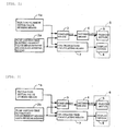
- Fig. 2 is a general block diagram of the oil-degradation determination apparatus according to the embodiment of the present invention.
- the oil-degradation determination apparatus shown in this embodiment is an apparatus for determining the degradation of oil that is circulated in and supplied to the engine of the motorcycle.
- the motorcycle includes an automatic manual transmission (hereafter, simply referred to as AMT) 20 that is joined to an engine 10, a hydraulic system 40 that controls the twin clutch of the AMT 20 as well as circulates and supplies oil to the engine 10, and an AMT control unit 60 that controls the AMT 20.
- AMT automatic manual transmission
- the oil-degradation determination apparatus is configured to determine the degradation of oil by inputting measured data on the electric-current value and the revolutions of an electric pump 41 used for re-circulating and supplying oil of the hydraulic system 40.
- the amount of oil supplied by an oil pump connected to and driven by the engine depends on the revolutions of the engine.
- the electric pump 41 used in the hydraulic system 40 is capable of preventing oil from being supplied excessively even when the engine revolves at a high speed, and of keeping the amount of circulated engine oil at an appropriate level, since the amount of oil to be circulated and supplied can be controlled by the driving current of the electric pump 41.
- the engine 10 includes a crankshaft 13 that is rotated by the reciprocating movement of multiple pistons 12 disposed in a cylinder block 11.
- a primary drive gear 31 is coupled to the crankshaft 13 which serves as the output shaft of the engine 10.
- the AMT 20 is an automatic manual transmission equipped with a twin clutch.
- the AMT 20 includes multiple-speed transmission gears 21, a first clutch 22, a second clutch 23, a shift drum 24, and a shift control motor 25.
- Each of the multiple gears included in the transmission gears 21 is either coupled to or loosely fitted to the corresponding one of a main shaft 26, a counter shaft 27, and a transmission-gear output shaft 28.
- the main shaft 26 includes an inner main shaft 26a and an outer main shaft 26b.
- the first clutch 22 is coupled to the inner main shaft 26a while the second clutch 23 is coupled to the outer main shaft 26b.
- Dog clutches (not illustrated) are provided respectively on the main shaft 26 and the counter shaft 27.
- the dog clutches thus provided are capable of being respectively displaced in the axial direction of the main shaft 26 and the counter shaft 27. Ends of each of shift forks 29 respectively engage with the dog clutch and a cam groove (not illustrated) formed in the shift drum 24.
- the primary drive gear 31 coupled to the crank shaft 13 of the engine 10 meshes with a primary driven gear 32 of the AMT 20.
- the primary driven gear 32 is connected to the inner main shaft 26a via the first clutch 22, and is also connected to the outer main shaft 26b via the second clutch 23.
- the hydraulic system 40 controls the connection of the first clutch 22 and the second clutch 23 to either the inner main shaft 26a or the outer main shaft 26b.
- a drive sprocket 35 is coupled to the counter shaft 27.
- the drive sprocket 35 is linked to a driven sprocket of the rear wheel of the motorcycle through a drive chain (not illustrated).
- the AMT 20 includes: an engine-revolution sensor 36 placed so as to face the outer circumference of the primary driven gear 32; a vehicle-speed sensor 37 placed so as to face the outer circumference of the gear coupled to the inner main shaft 26a subjected to the primary reduction; and a gear-position sensor 38 which detects the shift position accomplished by the shift drum 24.
- the hydraulic system 40 includes: an oil tank 42; a pipe 43 to feed the oil in the oil tank 42 to the first clutch 22 and to the second clutch 23; and a pipe 44 branched off from the pipe 43 so as to feed the oil to various parts of the engine 10.
- the hydraulic system 40 serves both as a hydraulic system to control the twin clutch of the AMT 20 and as a hydraulic system to circulate and supply the oil to the engine 10.
- the electric pump 41 is provided to the pipe 43 and the pipe 44 so that the oil in the oil tank 42 can be supplied both to the clutch side and to the engine side.
- the hydraulic pressure in each of the pipes 43 and 44 has to be kept below a certain value.
- a return pipe 46 is provided so as to return the oil to the oil tank via a regulator 45.
- the electric pump 41 is configured so that the amount of the oil supply may be determined by changing the revolutions of the pump in accordance with the value of the driving current.
- a data measurement apparatus 47 capable of detecting the value of the driving current and the revolutions of the pump is attached to the electric pump 41.
- a valve 55 is connected to the downstream side of the electric pump 41.
- the valve 55 includes two pressure chambers that make it possible to apply hydraulic pressure individually to the first clutch 22 and the second clutch 23. Additionally, return pipes 48 are connected respectively to the pressure chambers of the valve 55.
- a return pipe 49 is connected to the side of the engine 10, and allows the oil to be circulated in the engine 10 and supplied to the various parts of the engine.
- An oil-temperature sensor 50 to detect the temperature of the oil and a hydraulic-pressure sensor 51 to detect the pressure of the oil are provided in the pipe 43.
- an oil filter 52 to clean the circulated oil is provided between the electric pump 41 and the hydraulic-pressure sensor 51.
- An oil-amount detection sensor 53 to detect the amount of oil in the tank is provided on the bottom surface side of the oil tank 42.
- the oil-amount detection sensor can determine that an oil change has been done by detecting that the oil tank 42 has been emptied and then is filled again.
- a mode switch 61 and a shift-selector switch 62 are connected to the AMT control unit 60.
- the mode switch 61 is provided to switch between the automatic transmission (AT) and the manual transmission (MT).
- the shift-selector switch 62 designates either the up-shifting (UP) or the down-shifting (DN).
- the ATM control unit 60 receives information on the engine revolutions, the vehicle speed and the gear-shift position respectively obtained by the engine-revolution sensor 36, the vehicle-speed sensor 37, and the gear-position sensor 38 described above, information on the opening degree of the throttle obtained by a throttle sensor (not illustrated) provided on the throttle side, and the like.
- the AMT control unit 60 includes a micro computer (CPU).
- the AMT control unit 60 operates following a predetermined procedure in response to the output signals from the above-mentioned various sensors and switches, and thus controls the valve 55 and the shift control motor 25.
- the AMT control unit 60 controls the first clutch 22 and the second clutch 23 in response to the driving states, such as the vehicle speed, the engine revolutions, the gear position, and the throttle opening degree so as to automatically switch the transmission gears of the AMT 20.
- the AMT control unit 60 determines the degradation of the oil by detecting the measured data on the electric-current value and the revolutions by the data measurement apparatus 47 of the electric pump 41 and by detecting the temperature of oil by the oil-temperature sensor 50 provided in the pipe 43.
- the hydraulic pressure is applied either to the first clutch 22 or the second clutch 23, and the primary driven gear 32 is thus linked either to the inner main shaft 26a with the first clutch 22 or to the outer main shaft 26b with the second clutch 23.
- the primary driven gear 32 is biased, by each of return springs (not illustrated) that are built respectively in the first clutch 22 and the second clutch 23, to a direction such that the link with the inner main shaft 26a or the outer main shaft 26b can be disconnected.
- the shift control motor 25 moves rotatably the shift drum 24.
- the rotational motion of the shift drum 24 moves the shift forks 29 following the shape of the cam groove formed in the outer circumference of the shift drum 24.
- the shift forks 29 thus moved is displaced in the axial direction of the shift drum 24, and moves the dog clutches to select a different set of gears on the counter shaft 27 and the main shaft 26.
- the transmission gears 21 are either up-shifted or down-shifted.
- the AMT control unit 60 controls the first clutch 22 and the second clutch 23 in accordance with the driving conditions, such as the vehicle speed, the engine revolutions, the gear position, and the throttle opening degree so that the transmission gears 21 of the AMT 20 may be automatically up-shifted or down-shifted.
- the mode switch 61 is switched to "MT”
- the transmission gears 21 are up-shifted or down-shifted with the first clutch 22 and the second clutch 23 being operated in accordance with the driver's up-shifting or down-shifting operation of the selector switch 62.
- the electric-current initial-value storing means 1a is, in a case where the oil-amount detection sensor 53 detects that the oil tank 42 has been emptied of the oil and then is filled again with new oil (i.e. after an oil change has been done), configured to measure the electric-current value of the driving current for the electric pump 41 by using the data measurement apparatus 47 when the engine 10 is driven, and to store the value thus obtained as the electric-current initial value.
- the oil-degradation determination apparatus of this embodiment is configured to detect the change in the viscosity of oil by measuring the electric-current value of the above-mentioned driving current.
- the electric-current value for the electric pump 41 is measured while the engine is running, the electric pump 41 is constantly rotating at a predetermined rate, and the temperature of the oil detected by the oil-temperature sensor 50 is at a predetermined temperature.
- a revolution detecting device is provided in the data measurement apparatus 47 installed in the electric pump 41 so as to detect whether the electric pump 41 is being driven to rotate at the predetermined rate.
- the pump-driving-time electric-current value measurement means 2a is configured to collect data by measuring the electric-current value of the driving current of the electric pump 41 under conditions that the engine is being driven a predetermined time after the oil exchange, that the electric pump 41 is constantly rotating at the predetermined rate, and that the temperature of the oil is the same as that at the time when the electric-current initial value was measured.
- the revolution detecting device that is provided in the data measurement apparatus 47 installed in the electric pump 41 detects whether the electric pump 41 is being driven to rotate at the predetermined rate.
- the pump-driving-time electric-current value measurement means 2a is configured to be capable of collecting the data at desired regular intervals.
- the time elapsed after the change of the engine oil is managed by a built-in clock. Then, the data are collected, for example, at regular intervals set by the user or at regular intervals having been predetermined in advance (for example, for every ten days).
- the comparison means 3 is configured to compare the electric-current initial value stored in the electric-current initial-value storing means 1a and the electric-current value measured by the pump-driving-time electric-current value measurement means 2a.
- the determination means 4 determines that the viscosity of the oil has been lowered. Then, the determination means 4 outputs a signal to this effect to a warning device 5 connected to the determination means 4.
- the warning device 5 includes display means for showing visually the information by using light-emitting elements, a liquid crystal, or the like that is provided in a meter 6.
- the warning device 5 notifies the user of the degradation of the oil by lighting the display means (monitor lamp) in the meter 6 in response to the signal thus received.
- the lighting of the display by means of the display means may be replaced by or used together with a sound generating device that generates a warning sound.
- the oil-degradation determination apparatus is provided with data recording means that records pieces of data measured at regular intervals by the pump-driving-time electric-current value measurement means 2a. These pieces of data stored in the data recording means and the electric-current initial value stored in the electric-current initial-value storing means 1a are respectively outputted to oil-change time calculating means 7.
- the oil-change time calculating means 7 calculates how long it will take for the oil to reach a degraded state that requires the changing of oil (i.e., when to change the oil) by using a function having been stored in advance and used for obtaining the time at which the oil will be degraded.
- the user can be notified of the time of oil change thus calculated by displaying the information on a display device 8 in the meter 6.
- the measured data stored in the data recording means of the pump-driving-time electric-current value measurement means 2a and the electric-current initial value recorded in the electric-current initial-value storing means 1a are reset when the oil-amount detection sensor 53 detects that the oil tank is emptied of the oil.
- Fig. 3 is a general block diagram of an oil-degradation determination apparatus according to another embodiment of the present invention.
- the revolution initial-value storing means 1b is configured to measure the revolution of the electric pump 41 under conditions that the electric pump is running with a predetermined electric current, and that the temperature of oil detected by the oil-temperature sensor 50 is at a predetermined temperature, and to store therein the revolution thus measured as a revolution initial value.
- the pump-driving-time revolution measurement means 2b is configured to collect data by measuring the revolution of the electric pump 41 under conditions that the electric pump 41 is running with the predetermined electric current, and that the temperature of oil detected by the oil-temperature sensor 50 is the same as that at the time when the revolution initial value was measured.
- the oil-degradation determination apparatus of this embodiment is configured to detect the change in the viscosity of the oil by measuring the above-mentioned revolution.
- the revolution of the electric pump 41 is measured, when the engine is driven, under the conditions that the value of the driving current for the electric pump 41 is kept constantly at the predetermined electric-current value, and that the temperature of oil detected by the oil-temperature sensor 50 is kept constantly at the predetermined temperature. This excludes factors other than the degradation of the oil from the factors that may influence the revolution initial value and the revolution measured value of the electric pump 41 with the pump being driven, so that the degradation of the oil can be accurately reflected in the difference between the two revolutions.
- the comparison means 3 is configured to compare the revolution initial value and the revolution measured with the pump being driven. When the difference between the revolutions compared by the comparison means 3 is equal to or larger than a predetermined value, it is determined that the viscosity of the oil has become low.
- An electric-current detecting device is provided in the data measurement apparatus 47 installed in the electric pump 41 so as to detect whether the driving current for the electric pump 41 is kept constantly at the predetermined electric-current value during the driving of the electric pump 41.
- the electric pump 41 is configured to serve both as an electric pump for controlling the twin clutch and as an electric pump for circulating and supplying oil to the engine.
- two dedicated electric pumps may be respectively provided individually.
- the data measurement apparatus 47 which measures data to be outputted to the oil-degradation determination apparatus of the AMT control unit 60 and which serves both as the revolution detection device and the electric-current detection device, is provided on the side of the electric pump that circulates and supplies oil to the engine.
- the detection of the degradation of the engine oil does not rely on a special sensor that is in contact with the oil.
- the degradation of the oil can be determined by detecting the state of oil through the comparison either between the measured electric-current value for the electric pump and its initial value or between the measured revolution of the electric pump and its initial value. Accordingly, it is not necessary to install a sensor to detect physical properties of the oil. Consequently, the oil-degradation determination apparatus can have a simpler structure and can be manufactured at a lower cost.
Landscapes
- Engineering & Computer Science (AREA)
- Chemical & Material Sciences (AREA)
- Health & Medical Sciences (AREA)
- Life Sciences & Earth Sciences (AREA)
- Medicinal Chemistry (AREA)
- Biochemistry (AREA)
- Oil, Petroleum & Natural Gas (AREA)
- Chemical Kinetics & Catalysis (AREA)
- General Engineering & Computer Science (AREA)
- Food Science & Technology (AREA)
- Mechanical Engineering (AREA)
- Physics & Mathematics (AREA)
- Analytical Chemistry (AREA)
- General Chemical & Material Sciences (AREA)
- General Health & Medical Sciences (AREA)
- General Physics & Mathematics (AREA)
- Immunology (AREA)
- Pathology (AREA)
- Lubrication Details And Ventilation Of Internal Combustion Engines (AREA)
- Lubrication Of Internal Combustion Engines (AREA)
- Investigating Or Analyzing Materials By The Use Of Electric Means (AREA)
Claims (6)
- Ölverschlechterungsfeststellungsvorrichtung zum Feststellen der Verschlechterung von Öl, das in einem Motor (10) zirkuliert und diesem zugeführt wird, auf der Grundlage von gemessenen Daten an einer Elektropumpe (41), die das Öl in dem Motor (10) zirkuliert und diesem das Öl zuführt, wobei die Ölverschlechterungsfeststellungsvorrichtung aufweist:einen Öltemperaturfühler (50) zum Erfassen der Temperatur des Öls;eine Ausgangswertspeichereinrichtung, die einen elektrischen Stromwert eines Antriebsstroms misst, der zum Betreiben der Elektropumpe (41) mit einer vorgegebenen konstanten Umdrehung und einer vorgegebenen Öltemperatur eingesetzt wird, und den elektrischen Stromwert als einen elektrischen Ausgangsstromwert speichert;eine Messeinrichtung für Pumpenantriebszeitdaten, die Daten durch die Messung eines elektrischen Stromwertes eines Antriebsstroms erfasst, der zum Betreiben der Elektropumpe (41) mit der vorgegebenen konstanten Umdrehung und bei der vorgegebenen Öltemperatur eingesetzt wird, wenn der Motor (10) eine vorgegebene Zeit nach dem Speichern des elektrischen Ausgangsstromwertes angetrieben wird;eine Vergleichseinrichtung (3), die den elektrischen Ausgangsstromwert mit dem elektrischen Stromwert vergleicht, der in der vorgegebenen Zeit nach dem Speichern des elektrischen Ausgangsstromwertes gemessen wird;eine Feststellungseinrichtung (4), die feststellt, dass die Viskosität des Öls abgenommen hat unter der Bedingung, dass ein Unterschied zwischen den beiden von der Vergleichseinrichtung (3) verglichenen elektrischen Stromwerten gleich einem oder größer als ein vorgegebener Wert ist,
gekennzeichnet durch eine Datenaufzeichnungseinrichtung, die Teile von Daten aufzeichnet, die in regelmäßigen Abständen von der Messeinrichtung für Pumpenantriebszeitdaten gemessen werden; sowie
eine Berechnungseinrichtung der Ölwechselzeit (7), die aus den in der Datenaufzeichnungseinrichtung gespeicherten Datenteilen eine Zeit für den Ölwechsel berechnet. - Ölverschlechterungsfeststellungsvorrichtung zum Feststellen der Verschlechterung von Öl, das in einem Motor (10) zirkuliert und diesem zugeführt wird, auf der Grundlage von gemessenen Daten an einer Elektropumpe (41), die das Öl in dem Motor (10) zirkuliert und diesem das Öl zuführt, wobei die Ölverschlechterungsfeststellungsvorrichtung aufweist:einen Öltemperatursensor (50) zum Erfassen der Temperatur des Öls;eine Ausgangswertspeichereinrichtung, die eine Umdrehung der Elektropumpe (41) misst, wenn die Elektropumpe (41) mit einem vorgegebenen konstanten elektrischen Strom und bei einer vorgegebenen Öltemperatur betrieben wird, und die Umdrehung als einen Umdrehungsausgangswert speichert;eine Messeinrichtung für Pumpenantriebszeitdaten, die Daten durch die Messung einer Umdrehung der Elektropumpe (41) erfasst, während die Elektropumpe (41) mit dem vorgegebenen konstanten elektrischen Strom und bei der vorgegebenen Öltemperatur betrieben wird, wenn der Motor (10) eine vorgegebene Zeit nach dem Speichern des Umdrehungsausgangswertes angetrieben wird;eine Vergleichseinrichtung (3), die den Umdrehungsausgangswert mit der Umdrehung vergleicht, die in der vorgegebenen Zeit nach dem Speichern des Umdrehungsausgangswertes gemessen wird; sowieeine Feststellungseinrichtung (4), die feststellt, dass die Viskosität des Öls abgenommen hat unter der Bedingung, dass ein Unterschied zwischen den beiden von der Vergleichseinrichtung (3) verglichenen Umdrehungen gleich einem oder größer als ein vorgegebener Wert ist;gekennzeichnet durch eine Datenaufzeichnungseinrichtung, die Teile von Daten aufzeichnet, die in regelmäßigen Abständen von der Messeinrichtung für Pumpenantriebszeitdaten gemessen werden; sowie
eine Berechnungseinrichtung für die Ölwechselzeit (7), die aus den in der Datenaufzeichnungseinrichtung gespeicherten Datenteilen eine Zeit für den Ölwechsel berechnet. - Ölverschlechterungsfeststellungsvorrichtung gemäß einem der Ansprüche 1 und 2, ferner aufweisend:eine Warneinrichtung, die mindestens eine Anzeige ausgibt und/oder einen Ton erzeugt, wobei jeweils angezeigt wird, dass die Viskosität des Öls abgenommen hat, unter der Bedingung, dass die Feststellungseinrichtung (4) feststellt, dass die Viskosität des Öls abgenommen hat.
- Ölverschlechterungsfeststellungsvorrichtung gemäß einem der vorhergehenden Ansprüche,
wobei die Messeinrichtung für Pumpenantriebszeitdaten die Daten in gewünschten regelmäßigen Abständen erfasst. - Ölverschlechterungsfeststellungsvorrichtung gemäß Anspruch 1, wobei der elektrische Ausgangsstromwert unmittelbar nach dem Ölwechsel gemessen und gespeichert wird.
- Ölverschlechterungsfeststellungsvorrichtung gemäß Anspruch 2, wobei der Ausgangsumdrehungswert unmittelbar nach dem Ölwechsel gemessen und gespeichert wird.
Applications Claiming Priority (1)
| Application Number | Priority Date | Filing Date | Title |
|---|---|---|---|
| JP2008047761A JP5363008B2 (ja) | 2008-02-28 | 2008-02-28 | オイル劣化判定装置 |
Publications (3)
| Publication Number | Publication Date |
|---|---|
| EP2096434A2 EP2096434A2 (de) | 2009-09-02 |
| EP2096434A3 EP2096434A3 (de) | 2009-12-09 |
| EP2096434B1 true EP2096434B1 (de) | 2013-08-21 |
Family
ID=40512375
Family Applications (1)
| Application Number | Title | Priority Date | Filing Date |
|---|---|---|---|
| EP08171505.4A Not-in-force EP2096434B1 (de) | 2008-02-28 | 2008-12-12 | Vorrichtung zum Feststellen der Verschlechterung von einem Schmieröl |
Country Status (4)
| Country | Link |
|---|---|
| US (1) | US8342013B2 (de) |
| EP (1) | EP2096434B1 (de) |
| JP (1) | JP5363008B2 (de) |
| ES (1) | ES2426214T3 (de) |
Cited By (1)
| Publication number | Priority date | Publication date | Assignee | Title |
|---|---|---|---|---|
| DE102019206516A1 (de) * | 2019-05-07 | 2020-11-12 | Audi Ag | Hydrauliksystem für ein Fahrzeuggetriebe sowie Verfahren zum Betreiben des Hydrauliksystems |
Families Citing this family (17)
| Publication number | Priority date | Publication date | Assignee | Title |
|---|---|---|---|---|
| JP2011003007A (ja) * | 2009-06-18 | 2011-01-06 | Yamatake Corp | 施設管理装置及び施設管理方法 |
| DE202009017711U1 (de) * | 2009-12-31 | 2011-03-03 | Kalunka, Daniel | Messvorrichtung zur Fluidzustandsänderung |
| US9080522B2 (en) * | 2012-10-11 | 2015-07-14 | GM Global Technology Operations LLC | Engine efficiency system for a vehicle and method of operating an engine efficiency system |
| JP5942766B2 (ja) * | 2012-10-15 | 2016-06-29 | トヨタ自動車株式会社 | 内燃機関のオイルジェット装置 |
| DE102012112794B4 (de) * | 2012-12-20 | 2024-02-15 | Dr. Ing. H.C. F. Porsche Aktiengesellschaft | Verfahren zur Bestimmung eines Kraftstoffanteils in Öl |
| FR3010737B1 (fr) * | 2013-09-13 | 2015-08-21 | Turbomeca | Surveillance d'un degre de cokefaction au niveau de joints dynamiques par le demarreur |
| US9523320B2 (en) | 2013-10-15 | 2016-12-20 | Ford Global Technologies, Llc | Viscosity detection using sump |
| US9341129B2 (en) | 2013-10-15 | 2016-05-17 | Ford Global Technologies, Llc | Viscosity detection using starter motor |
| US9714931B2 (en) * | 2014-09-03 | 2017-07-25 | General Electric Company | System and method for estimating engine oil health |
| JP2016098755A (ja) * | 2014-11-25 | 2016-05-30 | いすゞ自動車株式会社 | エンジンオイルの劣化判定方法 |
| GB201522727D0 (en) * | 2015-12-23 | 2016-02-03 | Castrol Ltd | Apparatus and method |
| JP6308230B2 (ja) * | 2016-02-23 | 2018-04-11 | マツダ株式会社 | エンジンのオイル供給制御装置 |
| US12358399B2 (en) * | 2020-03-27 | 2025-07-15 | ExxonMobil Technology and Engineering Company | Monitoring health of heat transfer fluids for electric systems |
| US11378491B2 (en) * | 2020-04-03 | 2022-07-05 | Itt Manufacturing Enterprises Llc | Bearing frame monitoring system |
| WO2023278434A1 (en) | 2021-06-29 | 2023-01-05 | Donaldson Company, Inc. | Fluid condition sensing system and methods |
| CN116106173B (zh) * | 2023-04-07 | 2023-06-27 | 天津索克汽车试验有限公司 | 一种新能源汽车用机油粘度测量方法 |
| US12535091B2 (en) * | 2023-04-20 | 2026-01-27 | Deere & Company | Prognostics in hydraulic transmission system using e-machine drive |
Citations (1)
| Publication number | Priority date | Publication date | Assignee | Title |
|---|---|---|---|---|
| US6732572B1 (en) * | 1997-11-07 | 2004-05-11 | Volkswagen Ag | Method and device for monitoring and/or determining motor oil quality |
Family Cites Families (21)
| Publication number | Priority date | Publication date | Assignee | Title |
|---|---|---|---|---|
| JPH01136614U (de) * | 1988-03-14 | 1989-09-19 | ||
| JPH0326855A (ja) | 1989-06-22 | 1991-02-05 | Mazda Motor Corp | エンジンの制御装置 |
| JPH09317432A (ja) * | 1996-05-31 | 1997-12-09 | Tenetsukusu:Kk | エンジンオイル劣化検出装置 |
| DE19714087C2 (de) * | 1997-04-07 | 2000-06-21 | Rudolph Ehwald | Verfahren zur Affinitätsviskosimetrie und viskosimetrischer Affinitätssensor |
| JPH11101655A (ja) * | 1997-09-26 | 1999-04-13 | Nissan Diesel Motor Co Ltd | 車両モニタシステム |
| US6023961A (en) * | 1998-04-02 | 2000-02-15 | Reliance Electric Industrial Company | Micro-viscosity sensor and lubrication analysis system employing the same |
| DE10008547A1 (de) | 2000-02-24 | 2001-08-30 | Bosch Gmbh Robert | Verfahren zur Beurteilung des Verschleißes von Motoröl |
| DE10010976A1 (de) * | 2000-03-07 | 2001-09-13 | Bosch Gmbh Robert | Verfahren zur Beurteilung des Verschleißes von Motoröl unter Berücksichtigung einer Frischölnachfüllung |
| DE10055420A1 (de) * | 2000-11-09 | 2002-05-29 | Bosch Gmbh Robert | Vorrichtung zum Messen der Viskosität von Maschinen- und Motorenöl |
| JP4026324B2 (ja) * | 2001-03-16 | 2007-12-26 | いすゞ自動車株式会社 | エンジンオイル劣化判定方法および判定装置 |
| US6575018B2 (en) * | 2001-07-06 | 2003-06-10 | Delphi Technologies, Inc. | Method for determining oil viscosity |
| JP2003056324A (ja) * | 2001-08-09 | 2003-02-26 | Honda Motor Co Ltd | エンジンオイルの残存寿命表示装置 |
| US6640617B2 (en) * | 2001-08-16 | 2003-11-04 | Levitronix Llc | Apparatus and a method for determining the viscosity of a fluid |
| DE50203258D1 (de) * | 2001-12-04 | 2005-07-07 | Levitronix Llc Waltham | Abgabevorrichtung für ein Fluid |
| JP4004296B2 (ja) * | 2002-01-28 | 2007-11-07 | テルモ株式会社 | 遠心式液体ポンプ装置 |
| JP4101615B2 (ja) * | 2002-11-01 | 2008-06-18 | 本田技研工業株式会社 | エンジンオイルの劣化検出装置 |
| JP2004340033A (ja) * | 2003-05-15 | 2004-12-02 | Toyota Motor Corp | ドライサンプ給油式エンジンの異常判定装置 |
| JP4762498B2 (ja) * | 2004-01-22 | 2011-08-31 | ヤマハ発動機株式会社 | 車両用距離表示装置 |
| AT500358B1 (de) * | 2004-05-24 | 2007-09-15 | Anton Paar Gmbh | Rotationsrheometer bzw. -viskosimeter |
| KR100795403B1 (ko) * | 2006-06-02 | 2008-01-17 | 파웰테크윈주식회사 | 엔진의 회전수를 이용한 오일교환 경보장치 |
| US7677086B2 (en) * | 2007-03-12 | 2010-03-16 | Gm Global Technology Operations, Inc. | Engine oil viscosity diagnostic systems and methods |
-
2008
- 2008-02-28 JP JP2008047761A patent/JP5363008B2/ja not_active Expired - Fee Related
- 2008-12-12 EP EP08171505.4A patent/EP2096434B1/de not_active Not-in-force
- 2008-12-12 ES ES08171505T patent/ES2426214T3/es active Active
-
2009
- 2009-02-02 US US12/364,065 patent/US8342013B2/en active Active
Patent Citations (1)
| Publication number | Priority date | Publication date | Assignee | Title |
|---|---|---|---|---|
| US6732572B1 (en) * | 1997-11-07 | 2004-05-11 | Volkswagen Ag | Method and device for monitoring and/or determining motor oil quality |
Cited By (1)
| Publication number | Priority date | Publication date | Assignee | Title |
|---|---|---|---|---|
| DE102019206516A1 (de) * | 2019-05-07 | 2020-11-12 | Audi Ag | Hydrauliksystem für ein Fahrzeuggetriebe sowie Verfahren zum Betreiben des Hydrauliksystems |
Also Published As
| Publication number | Publication date |
|---|---|
| EP2096434A3 (de) | 2009-12-09 |
| ES2426214T3 (es) | 2013-10-22 |
| US20090217740A1 (en) | 2009-09-03 |
| JP5363008B2 (ja) | 2013-12-11 |
| EP2096434A2 (de) | 2009-09-02 |
| JP2009203916A (ja) | 2009-09-10 |
| US8342013B2 (en) | 2013-01-01 |
Similar Documents
| Publication | Publication Date | Title |
|---|---|---|
| EP2096434B1 (de) | Vorrichtung zum Feststellen der Verschlechterung von einem Schmieröl | |
| CN101265970B (zh) | 用于确定变速器过滤器的剩余使用寿命的装置和方法 | |
| US8050814B2 (en) | Apparatus and method for determining remaining transmission oil life | |
| US8788169B2 (en) | Clutch control device | |
| US7433770B2 (en) | Hydraulic fluid change indicating device for automatic transmission | |
| US20070175720A1 (en) | Control device and control method for vehicle | |
| US8255133B2 (en) | Shift timing indicator system for vehicular manual transmission | |
| CN101936382A (zh) | 控制车辆运行的方法 | |
| JPH09280348A (ja) | 変速機のクラッチの摩耗検出方法及びその検出装置 | |
| JP2008057670A (ja) | クラッチの発熱量推定装置 | |
| US9280856B2 (en) | Method and apparatus for estimating replacement of vehicle engine oil | |
| KR20180066757A (ko) | 다단 자동변속기의 클러치 마찰계수 학습 제어 장치 및 방법, 그리고 클러치 마찰계수 학습 제어 장치를 포함하는 다단 자동변속기 | |
| JP4254554B2 (ja) | 船外機のエンジン管理装置 | |
| JP2014070715A (ja) | 車両用摩擦クラッチの過負荷履歴保存装置 | |
| JP2006275929A (ja) | 部品劣化度評価装置及び部品劣化度評価方法 | |
| GB2415752A (en) | A method of montioring the condition of a bearing or engine | |
| CN108071787B (zh) | 使用润滑补偿器模型调整用于变速器的离合器填充命令压力的方法 | |
| KR100793701B1 (ko) | 자동 변속기의 오일량 점검 방법 | |
| JP4037854B2 (ja) | 建設機械の走行駆動制御装置 | |
| KR200204922Y1 (ko) | 회전팬을 이용한 엔진 오일 교환시기 알림장치 | |
| FR2792982A1 (fr) | Procede pour obtenir une information caracterisant un etat de fonctionnement d'un embrayage a friction | |
| KR0170918B1 (ko) | 자동차 변속기의 오일교환시기 표시장치 | |
| KR20020081624A (ko) | 오일팬의 오일 보충장치 | |
| KR100230924B1 (ko) | 차량의 자동변속기 오일량 감지장치 | |
| US20070142141A1 (en) | Method and apparatus for monitoring the operational reliability of a transmission that transmits torque by frictional engagement |
Legal Events
| Date | Code | Title | Description |
|---|---|---|---|
| PUAI | Public reference made under article 153(3) epc to a published international application that has entered the european phase |
Free format text: ORIGINAL CODE: 0009012 |
|
| 17P | Request for examination filed |
Effective date: 20081212 |
|
| AK | Designated contracting states |
Kind code of ref document: A2 Designated state(s): AT BE BG CH CY CZ DE DK EE ES FI FR GB GR HR HU IE IS IT LI LT LU LV MC MT NL NO PL PT RO SE SI SK TR |
|
| AX | Request for extension of the european patent |
Extension state: AL BA MK RS |
|
| PUAL | Search report despatched |
Free format text: ORIGINAL CODE: 0009013 |
|
| AK | Designated contracting states |
Kind code of ref document: A3 Designated state(s): AT BE BG CH CY CZ DE DK EE ES FI FR GB GR HR HU IE IS IT LI LT LU LV MC MT NL NO PL PT RO SE SI SK TR |
|
| AX | Request for extension of the european patent |
Extension state: AL BA MK RS |
|
| 17Q | First examination report despatched |
Effective date: 20100129 |
|
| AKX | Designation fees paid |
Designated state(s): DE ES IT |
|
| GRAP | Despatch of communication of intention to grant a patent |
Free format text: ORIGINAL CODE: EPIDOSNIGR1 |
|
| INTG | Intention to grant announced |
Effective date: 20130503 |
|
| RIN1 | Information on inventor provided before grant (corrected) |
Inventor name: NEDACHI, YOSHIAKI Inventor name: TSUNASHIMA, KOUSUKE Inventor name: OZEKI, TAKASHI |
|
| GRAS | Grant fee paid |
Free format text: ORIGINAL CODE: EPIDOSNIGR3 |
|
| GRAA | (expected) grant |
Free format text: ORIGINAL CODE: 0009210 |
|
| AK | Designated contracting states |
Kind code of ref document: B1 Designated state(s): DE ES IT |
|
| REG | Reference to a national code |
Ref country code: DE Ref legal event code: R096 Ref document number: 602008026921 Country of ref document: DE Effective date: 20131017 |
|
| REG | Reference to a national code |
Ref country code: ES Ref legal event code: FG2A Ref document number: 2426214 Country of ref document: ES Kind code of ref document: T3 Effective date: 20131022 |
|
| PLBE | No opposition filed within time limit |
Free format text: ORIGINAL CODE: 0009261 |
|
| STAA | Information on the status of an ep patent application or granted ep patent |
Free format text: STATUS: NO OPPOSITION FILED WITHIN TIME LIMIT |
|
| 26N | No opposition filed |
Effective date: 20140522 |
|
| REG | Reference to a national code |
Ref country code: DE Ref legal event code: R084 Ref document number: 602008026921 Country of ref document: DE |
|
| REG | Reference to a national code |
Ref country code: DE Ref legal event code: R097 Ref document number: 602008026921 Country of ref document: DE Effective date: 20140522 |
|
| REG | Reference to a national code |
Ref country code: DE Ref legal event code: R084 Ref document number: 602008026921 Country of ref document: DE Effective date: 20140821 |
|
| PGFP | Annual fee paid to national office [announced via postgrant information from national office to epo] |
Ref country code: DE Payment date: 20171206 Year of fee payment: 10 |
|
| PGFP | Annual fee paid to national office [announced via postgrant information from national office to epo] |
Ref country code: ES Payment date: 20180102 Year of fee payment: 10 |
|
| PGFP | Annual fee paid to national office [announced via postgrant information from national office to epo] |
Ref country code: IT Payment date: 20171221 Year of fee payment: 10 |
|
| REG | Reference to a national code |
Ref country code: DE Ref legal event code: R119 Ref document number: 602008026921 Country of ref document: DE |
|
| PG25 | Lapsed in a contracting state [announced via postgrant information from national office to epo] |
Ref country code: DE Free format text: LAPSE BECAUSE OF NON-PAYMENT OF DUE FEES Effective date: 20190702 Ref country code: IT Free format text: LAPSE BECAUSE OF NON-PAYMENT OF DUE FEES Effective date: 20181212 |
|
| REG | Reference to a national code |
Ref country code: ES Ref legal event code: FD2A Effective date: 20200203 |
|
| PG25 | Lapsed in a contracting state [announced via postgrant information from national office to epo] |
Ref country code: ES Free format text: LAPSE BECAUSE OF NON-PAYMENT OF DUE FEES Effective date: 20181213 |