EP2096516A2 - Station d'accueil dotée d'une connexion rapide pour un appareil électronique mobile - Google Patents
Station d'accueil dotée d'une connexion rapide pour un appareil électronique mobile Download PDFInfo
- Publication number
- EP2096516A2 EP2096516A2 EP09002626A EP09002626A EP2096516A2 EP 2096516 A2 EP2096516 A2 EP 2096516A2 EP 09002626 A EP09002626 A EP 09002626A EP 09002626 A EP09002626 A EP 09002626A EP 2096516 A2 EP2096516 A2 EP 2096516A2
- Authority
- EP
- European Patent Office
- Prior art keywords
- housing
- docking station
- quick release
- locking
- locking block
- Prior art date
- Legal status (The legal status is an assumption and is not a legal conclusion. Google has not performed a legal analysis and makes no representation as to the accuracy of the status listed.)
- Withdrawn
Links
Images
Classifications
-
- G—PHYSICS
- G06—COMPUTING OR CALCULATING; COUNTING
- G06F—ELECTRIC DIGITAL DATA PROCESSING
- G06F1/00—Details not covered by groups G06F3/00 - G06F13/00 and G06F21/00
- G06F1/16—Constructional details or arrangements
- G06F1/1613—Constructional details or arrangements for portable computers
- G06F1/1632—External expansion units, e.g. docking stations
Definitions
- the invention relates to a mobile electronic device such as a computer, in particular a notebook, a laptop, a tablet PC or the like., According to the preamble of claim 1.
- Mobile electronic devices are designed according to their preferred use and are powered by built-in or removable batteries with energy. Each mobile electronic device is usually associated with a docking station, which often serves as a charging station and also provides additional connections for other peripherals. If a docking station with a deployed mobile device is used as a workstation, a reliable mechanical connection between the mobile device and the docking station must be ensured.
- the invention has for its object to connect a mobile electronic device in a simple way mechanically fixed and yet easily detachable with a docking station.
- the engaging in a wall of the housing mechanical quick release ensures a mechanically strong connection between the housing of the device and the docking station itself and allows the user due to the quick release technology easy release of the device from the docking station in the case of a mobile use.
- the device is mechanically held firmly at the docking station with only one quick release.
- the mechanically fixed connection is provided in particular on the rear side of the device, for example centrally in its base plate and preferably adjacent to an electrical connection, so that the electrical connection is securely connected and mechanically largely kept free of carrying forces.
- the quick release cooperates with a latch plate which is fixed to the housing of the mobile electronic device, preferably inside the housing.
- the latch plate is held in a latch block which can be fixed on the motherboard.
- the locking block is preferably firmly connected to the housing of the device.
- the locking block is screwed to the bottom plate of the housing, wherein the electrical connection is surrounded by the locking block.
- the electrical connection is within the contour of attachment points of the locking block.
- a seal is arranged between the end faces of the locking block and the housing.
- a thimble-like seal can be inserted into the opening of the housing, which surrounds the protruding part of the quick release and rests with a sealing edge on the wall with the opening. The interior of the housing is so securely sealed despite the opening for the quick release to the outside.
- the mechanically fixed connection between the housing of the mobile device and the docking station or its support arm is secured by a mechanical lock.
- the lock cooperates with the mechanical quick release and is designed in particular as an electromagnetically actuated lock which is activated as a function of the output signal of a reading device for an RFID tag, a SMART card or the like.
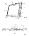
- the mobile electronic device shown in the embodiment is designed as a tablet PC 1 having a housing 2 for receiving a motherboard 3 (FIG. Fig. 3 ), are arranged on the computer-typical components such as a processor, a random access memory and / or a storage volume.
- the display unit 4 is a preferably touch-sensitive Screen (touch screen) provided, which can also be used as input unit 5. It may be expedient to arrange function buttons 6, a switch-off switch 7 and indicator lights 8 in the edge region of the display unit 4 or of the screen.
- the mobile, portable device 1 is fed from a housing-internal power source, which may be formed as a battery, preferably as a battery 9.
- Fig. 1 shows, parallel to the longitudinal sides 10, 11 each a battery pack 9 are arranged, which preferably extend substantially over the entire width B of the device 1.
- a receptacle 13 for a quick release 14 is formed in a wall 12 of the housing 2, which is located approximately centrally in the back 12 in a preferred embodiment.
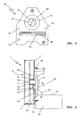
- the quick release 14 is a ball detent 15, which in the 3 and 4 shown in detail.
- the ball catch 15 consists essentially of a central, cylindrical base housing 16, which is cup-shaped closed at its lower end 17. Above the lower end 17 locking balls 18 are arranged in openings 20 of the cylinder wall 19, wherein the diameter of a detent ball 18 is greater than the opening diameter of an opening 20. The arranged in the interior of the base housing 16 detent balls 18 can thus not pass through the openings 20.
- the position of the detent balls 18 is determined by a central cylindrical pin 21, which is at a distance from its lower, in the base housing 16 lying end 23 a circumferential annular groove 24 shows.
- the end 23 shows a peripheral edge 25, which presses the locking balls 18 in the direction of arrow 26 to the outside.
- the dimensions are such that the detent balls 18 are held by the peripheral edge 25 to stop fixed in the openings 20, wherein the cylindrical pin 21 is held by the detent balls at the same time so that it can not escape from the base housing 16.
- This in Fig. 4 Locking position shown is stabilized by a spring 22 which is disposed between the bottom of the end 17 of the base housing 16 and the end 23 of the cylindrical pin 21.
- the other, free end 27 of the cylindrical pin 21 projects out of the base housing 16.
- the locking balls 18 can recede into the annular groove 24, so that they do not protrude further beyond the diameter 37 of the outer circumference of the cylindrical base housing 16.
- the detent balls 18 are in their release position.
- the cylindrical base housing 16 is further surrounded by a switching sleeve 30, which is acted upon by a spring 29 in the direction of the lower end 17 of the base housing 16.
- the shift sleeve 30 can rest with its lower end 31 to the locking position lying in the locking position 18. If the cylindrical pin 21 pressed down in the direction of arrow 28, the locking balls 18 due to the spring-loaded shift sleeve 30 dodge radially inwardly into the annular groove 24, so that the locking balls 18 are forcibly moved to its release position.
- the shift sleeve 30 passes over the balls 18 so far, that they lie substantially over half their circumference within the shift sleeve 30.
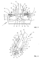
- the ball catch 15 preferably cooperates with a locking block 40 which is mounted in the housing 2 of the mobile electronic device 1 and is accessible via a central opening 33 in the bottom plate 35 of the housing 2.
- the latch block 40 may be mounted on the main board 3 for fixing the position; power transmitting the latch block 40 is connected to fasteners 34 of the bottom plate 35 of the back 12, so that the mechanical forces are absorbed by the housing 2 itself.
- the motherboard 3 remains largely free of bearing forces.
- a locking plate 41 is fixed in the locking block 40, preferably cast, wherein the locking plate 41 in the illustrated embodiment, an inner circumferential locking edge 42 has.
- threaded inserts 43 are preferably provided in the locking block 40. It may also be expedient to connect the latch plate 41 directly to the bottom plate 35 or to pour into it.
- the latch plate 41 is made of steel, in particular hardened steel, to enter into a solid mechanical bond with the ball latch 15.
- the plug connection 44 may further be provided, which is fixed directly on the motherboard 3. In order to keep the plug-in connection 44 free from bearing forces, this is located at a mutual distance in a recess 45 of the locking block 40.
- FIG. 2 shows the ball detent closure 15 engaging in the mobile electronic device 1, which housing is fixedly mounted on a support arm 51 of a docking station 50 (FIG. Fig. 6 ).
- a docking station 50 FIG. Fig. 6
- the housing 2 for receiving the approximately centrally engaging ball detent 15 in the back 12 must have an opening 33, to seal the housing 2, a sealing cap 60 (FIG. Fig. 6 ) inserted into the opening 33, in which the ball catch 15th protrudes.
- the trained in the manner of a thimble sealing cap 60 bears with a sealing edge 61 sealingly on the bottom plate 35 at.
- the inner diameter of the thimble-like sealing cap is larger than the inner diameter 47 of the locking edge 42, so that the protruding into the housing 2 portion of the ball catch 15 is surrounded with little play.
- the function of the quick release 14 is not hindered by the cup-shaped sealing cap 60.
- the end 17 of the base housing 16 is threaded into the opening 33 and the central opening 46 of the latch plate 41.
- the inner diameter 47 of the opening 46 is slightly larger than the outer diameter 37 of the projecting end 17 of the base housing 16.
- the inner diameter 47 is smaller than the outer diameter 38 of the shift sleeve 30, so that when placing the housing 2 on the ball latch 15, the latch plate 41st at the end 31 of the shift sleeve 30 abuts.
- the shift sleeve 30 deviates in the direction of arrow 32, so that the locking balls 18 can emerge radially from the openings 20 and engage under the latching edge 42 of the latch plate 41.
- the housing 2 or the mobile electronic device 1 is held mechanically fixed on the approximately central ball catch 15 of the docking station 50.
- the placement of the housing 2 on the ball latch 15 takes place in the direction of arrow 39 ( Fig. 3 ), which corresponds to the plugging direction of the plug connection 44. With the placement of the housing 2 on the ball latch 15 is thus simultaneously the plug connection 44 plugged together, so that the desired electrical connection of the mobile electronic device 1 is made with the docking station 50.
- the sealing cap 60 is provided; Alternatively or additionally, between the front side 49 of the locking block 40 and the motherboard 3 and between the end face 48 of the locking block 40 and the bottom plate 35 each have a seal are arranged. Since the locking block 40 completely surrounds the locking plate 41 and the plug connection 44 fixed on the main circuit board 3, seals are expedient which cover substantially the entire end face 48, 49 of the locking block 40. Such seals also ensure complete sealing of the bolt receptacle to the outside.
- the user To release the device 1 from the support arm 51 of the docking station 50 is the user only the dowel pin 21 depress.
- the detent balls 18 can recede into the annular groove 24 and release the latch plate 41.
- the device 1 can be removed in the opposite direction of the arrow 39, at the same time the plug-in connection 44 is released.
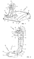
- the docking station 50 may comprise a support arm 51 for the mobile electronic device 1, in the exemplary embodiment a tablet PC 1.
- the quick release 14, described in the embodiment of the quick-release ball 15, is fixedly mounted in the support arm 51, so that when pushed in the direction of arrow 39 on the ball latch 15 of the support arm 51 at the same time the connector 44 is connected.
- a plug 52 and on the side of the support arm 51 a bushing 53 is provided.
- a buffer made of soft material or a stopper 54 is provided, which supports the housing 2 against the support arm 51.
- the support arm 51 is pivotally supported about a pivot axis 55 in the direction of arrow 56 to the docking station 50, so that the display unit 4 can be adjusted according to the working conditions on site.
- the positions of the support arm 51 are suitable latched.
- This housing 57 can be mounted by means of mounting rails 61 on a solid support, not shown, including the mounting rails 61 end over the bottom plate of the housing 57 and Attachment openings 62 have.
- On the housing 57 is - preferably pivotally - the support arm 51 is provided, the mechanical quick release 15 for the aufdinde mobile electronic device, namely the tablet PC 1, at its free end.
- Below the quick release 15 is - transverse to the longitudinal axis 63 of the support arm 51 - the connector 44 is provided which is formed in the embodiment shown as a plug, but may also be a socket.
- the plug 52 or the socket 53 engages in a corresponding socket 53 or plug 52 on the back of the mobile electronic device, namely the tablet PC 1, a.
- the support arm 51 is after pressing an unlock button 59 in the direction of arrow 56 ( Fig. 6 ), wherein it can be fixed in structurally predetermined locking positions corresponding to the desired tilting position of the support arm 51.
- a lock 65 is provided at the end of the support arm 42 near the housing. In the illustrated embodiment, this is designed as a lock 70; other versions may be appropriate.
- the lock 70 with the quick release 15 cooperate such that in the locked position of the lock 70, the lock of the quick release 14 is blocked and in the open position of the lock 70, the quick release 14 is actuated.
- the lock 70 blocks an actuating button 64, via which the quick-release closure 14 is triggered.
- a pull rod 73 is connected, the other, distal end 74 acts on a rocker arm 75 which is held in a pivot bearing 76.
- the rocker arm 75 presses due to the train on the pull rod 73 with one end 77 on the cylindrical pin 21 of the quick release 14 and pushes it in the direction of arrow 28 in its release position.
- the device can be removed from the support arm. By placing the device 1 on the support arm 51 of the cylinder pin 21 is pushed back and pivots the rocker arm 75 back to its original position.
- lock 70 an electromagnetic lock, the z. B. via a manually entered code or a day reader with an RFID tag or a SMART card is operated. If the correct code is detected, depending on the output signal of a reader, the electromagnetic lock 70 opens the locking latch 66, and the user can pivot the actuating button 64 to open the quick-release closure 14.
- the reader 80 for identifying the user may be integrated in the electronic device itself, namely the tablet PC 1, or in the housing 57 of the docking station 50. If the user identified as an authorized user, the electromagnetic actuation of the lock 70 and thus the mechanical release of the device.
- the opening 33 is provided for engagement of the quick release 14 on the back 12 of the housing 2 and the ball detent 15 is held on the support arm 51 of the docking station 50. It may also be advantageous to fix the quick release 14 itself on the housing 2 and to provide the corresponding receiving opening 33 on the arm 51 of the docking station 50.
Landscapes
- Engineering & Computer Science (AREA)
- Theoretical Computer Science (AREA)
- Computer Hardware Design (AREA)
- Human Computer Interaction (AREA)
- Physics & Mathematics (AREA)
- General Engineering & Computer Science (AREA)
- General Physics & Mathematics (AREA)
- Telephone Set Structure (AREA)
- Details Of Connecting Devices For Male And Female Coupling (AREA)
- Coupling Device And Connection With Printed Circuit (AREA)
- Casings For Electric Apparatus (AREA)
Priority Applications (1)
| Application Number | Priority Date | Filing Date | Title |
|---|---|---|---|
| EP09002626A EP2096516A3 (fr) | 2008-02-26 | 2009-02-25 | Station d'accueil dotée d'une connexion rapide pour un appareil électronique mobile |
Applications Claiming Priority (5)
| Application Number | Priority Date | Filing Date | Title |
|---|---|---|---|
| EP08003450 | 2008-02-26 | ||
| EP08003457 | 2008-02-26 | ||
| EP08005595 | 2008-03-26 | ||
| EP08005596A EP2096514A3 (fr) | 2008-02-26 | 2008-03-26 | Station d'acceuil pour un appareil électronique mobile |
| EP09002626A EP2096516A3 (fr) | 2008-02-26 | 2009-02-25 | Station d'accueil dotée d'une connexion rapide pour un appareil électronique mobile |
Publications (2)
| Publication Number | Publication Date |
|---|---|
| EP2096516A2 true EP2096516A2 (fr) | 2009-09-02 |
| EP2096516A3 EP2096516A3 (fr) | 2011-06-29 |
Family
ID=40718653
Family Applications (1)
| Application Number | Title | Priority Date | Filing Date |
|---|---|---|---|
| EP09002626A Withdrawn EP2096516A3 (fr) | 2008-02-26 | 2009-02-25 | Station d'accueil dotée d'une connexion rapide pour un appareil électronique mobile |
Country Status (1)
| Country | Link |
|---|---|
| EP (1) | EP2096516A3 (fr) |
Cited By (3)
| Publication number | Priority date | Publication date | Assignee | Title |
|---|---|---|---|---|
| CN102327716A (zh) * | 2011-08-02 | 2012-01-25 | 江阴市化工机械有限公司 | 一种除尘器 |
| WO2014049365A1 (fr) * | 2012-09-26 | 2014-04-03 | X2 Computing Limited | Appareil de support pour ordinateur mobile |
| EP3267283A1 (fr) | 2016-07-06 | 2018-01-10 | Siemens Aktiengesellschaft | Dispositif de reception pour un appareil electronique portatif |
Family Cites Families (3)
| Publication number | Priority date | Publication date | Assignee | Title |
|---|---|---|---|---|
| DE3129700A1 (de) * | 1981-07-28 | 1983-02-17 | Blasius 8019 Glonn Gerg | Gabelbaum fuer ein rigg eines segelsurfers |
| DE9203955U1 (de) * | 1992-03-24 | 1992-06-11 | Ueth & Haug GmbH, 7200 Tuttlingen | Medizinisches Spül- und Sauginstrument |
| JP2005321998A (ja) * | 2004-05-07 | 2005-11-17 | Sony Corp | 携帯型コンピュータ用ドッキング装置およびドッキング構造 |
-
2009
- 2009-02-25 EP EP09002626A patent/EP2096516A3/fr not_active Withdrawn
Cited By (4)
| Publication number | Priority date | Publication date | Assignee | Title |
|---|---|---|---|---|
| CN102327716A (zh) * | 2011-08-02 | 2012-01-25 | 江阴市化工机械有限公司 | 一种除尘器 |
| WO2014049365A1 (fr) * | 2012-09-26 | 2014-04-03 | X2 Computing Limited | Appareil de support pour ordinateur mobile |
| GB2512265A (en) * | 2012-09-26 | 2014-10-01 | X2 Computing Ltd | Mobile-computer support apparatus |
| EP3267283A1 (fr) | 2016-07-06 | 2018-01-10 | Siemens Aktiengesellschaft | Dispositif de reception pour un appareil electronique portatif |
Also Published As
| Publication number | Publication date |
|---|---|
| EP2096516A3 (fr) | 2011-06-29 |
Similar Documents
| Publication | Publication Date | Title |
|---|---|---|
| DE112016005628B4 (de) | Elektronisches zahlenschloss mit verschiedenen ebenen der zugriffskontrolle | |
| EP2734694B1 (fr) | Dispositif de verrouillage de bouchon de réservoir | |
| EP2306418B1 (fr) | Station service électrique | |
| EP0186737B1 (fr) | Dispositif d'introduction d'une carte de données à circuit électronique | |
| DE112013003564B4 (de) | Baugruppe mit elektronisch betätigtem Verriegelungsmechanismus für Schubladenschienen | |
| DE102013206692B3 (de) | Vorrichtung zum Halten eines tragbaren elektronischen Geräts | |
| DE102006011712B4 (de) | Tragbares elektronisches Gerät mit einer verriegelten Batterieabdeckung und Mechanismus zum Anheben der Abdeckung | |
| DE102010041317B4 (de) | Ladeeinrichtung für ein Elektrofahrzeug nebst Verfahren | |
| DE112007001299T5 (de) | Nockenschloss mit rückziehbarem Dorn | |
| EP2300674B1 (fr) | Serrure pourvue d une commande manuelle et distante et destinée à des contenants mobiles ou portables | |
| DE102018128579A1 (de) | Türverriegelungsvorrichtung | |
| DE202022100159U1 (de) | Schlosszungenmodul und modulares Schlosssystem | |
| EP2096516A2 (fr) | Station d'accueil dotée d'une connexion rapide pour un appareil électronique mobile | |
| DE3786428T2 (de) | Sicherheitssystem. | |
| DE102008057034B4 (de) | Vorrichtung zum Öffnen einer Tür | |
| DE19736561A1 (de) | Verschlußklappe für Behältnisse wie Ablagefächer, Aschenbecher und dergleichen, insbesondere für Kraftfahrzeuge, sowie Verfahren zum Öffnen einer Verschlußklappe | |
| EP3033464A1 (fr) | Dispositif pourvu d'un mécanisme « push-push » | |
| DE202022102693U1 (de) | Installationsstruktur einer Batterie und Elektrofahrzeug | |
| DE202013008865U1 (de) | Zahlenschloss | |
| DE102005044720B4 (de) | Aufnahmehalter für einen Telefonhalter | |
| EP3121353B1 (fr) | Serrure pour une cle a pipe | |
| DE102023118762A1 (de) | Lade-, tank- oder serviceklappe | |
| DE102012015414A1 (de) | Steckdose mit Verschlussmechanismus | |
| EP2055871A2 (fr) | Fermeture d'armoire de consigne à pièces de monnaies | |
| DE202008005402U1 (de) | Elektrische Schließvorrichtung |
Legal Events
| Date | Code | Title | Description |
|---|---|---|---|
| PUAI | Public reference made under article 153(3) epc to a published international application that has entered the european phase |
Free format text: ORIGINAL CODE: 0009012 |
|
| AK | Designated contracting states |
Kind code of ref document: A2 Designated state(s): AT BE BG CH CY CZ DE DK EE ES FI FR GB GR HR HU IE IS IT LI LT LU LV MC MK MT NL NO PL PT RO SE SI SK TR |
|
| AX | Request for extension of the european patent |
Extension state: AL BA RS |
|
| PUAL | Search report despatched |
Free format text: ORIGINAL CODE: 0009013 |
|
| AK | Designated contracting states |
Kind code of ref document: A3 Designated state(s): AT BE BG CH CY CZ DE DK EE ES FI FR GB GR HR HU IE IS IT LI LT LU LV MC MK MT NL NO PL PT RO SE SI SK TR |
|
| AX | Request for extension of the european patent |
Extension state: AL BA RS |
|
| AKY | No designation fees paid | ||
| REG | Reference to a national code |
Ref country code: DE Ref legal event code: R108 Effective date: 20120307 |
|
| STAA | Information on the status of an ep patent application or granted ep patent |
Free format text: STATUS: THE APPLICATION IS DEEMED TO BE WITHDRAWN |
|
| 18D | Application deemed to be withdrawn |
Effective date: 20111230 |