EP2096602A1 - Verfahren und Vorrichtung zur Startbahnsegmentierung mittels Sensoranalyse - Google Patents
Verfahren und Vorrichtung zur Startbahnsegmentierung mittels Sensoranalyse Download PDFInfo
- Publication number
- EP2096602A1 EP2096602A1 EP09152623A EP09152623A EP2096602A1 EP 2096602 A1 EP2096602 A1 EP 2096602A1 EP 09152623 A EP09152623 A EP 09152623A EP 09152623 A EP09152623 A EP 09152623A EP 2096602 A1 EP2096602 A1 EP 2096602A1
- Authority
- EP
- European Patent Office
- Prior art keywords
- blob
- runway
- slope
- template
- corner
- Prior art date
- Legal status (The legal status is an assumption and is not a legal conclusion. Google has not performed a legal analysis and makes no representation as to the accuracy of the status listed.)
- Granted
Links
Images


Classifications
-
- G—PHYSICS
- G06—COMPUTING OR CALCULATING; COUNTING
- G06T—IMAGE DATA PROCESSING OR GENERATION, IN GENERAL
- G06T7/00—Image analysis
- G06T7/70—Determining position or orientation of objects or cameras
-
- G—PHYSICS
- G06—COMPUTING OR CALCULATING; COUNTING
- G06T—IMAGE DATA PROCESSING OR GENERATION, IN GENERAL
- G06T7/00—Image analysis
- G06T7/10—Segmentation; Edge detection
- G06T7/11—Region-based segmentation
-
- G—PHYSICS
- G06—COMPUTING OR CALCULATING; COUNTING
- G06V—IMAGE OR VIDEO RECOGNITION OR UNDERSTANDING
- G06V20/00—Scenes; Scene-specific elements
- G06V20/10—Terrestrial scenes
- G06V20/13—Satellite images
-
- G—PHYSICS
- G06—COMPUTING OR CALCULATING; COUNTING
- G06T—IMAGE DATA PROCESSING OR GENERATION, IN GENERAL
- G06T2207/00—Indexing scheme for image analysis or image enhancement
- G06T2207/10—Image acquisition modality
- G06T2207/10048—Infrared image
-
- G—PHYSICS
- G06—COMPUTING OR CALCULATING; COUNTING
- G06T—IMAGE DATA PROCESSING OR GENERATION, IN GENERAL
- G06T2207/00—Indexing scheme for image analysis or image enhancement
- G06T2207/30—Subject of image; Context of image processing
- G06T2207/30248—Vehicle exterior or interior
- G06T2207/30252—Vehicle exterior; Vicinity of vehicle
Definitions
- the present invention relates generally to providing guidance to aircraft crew, and more particularly, relates to forming a combined sensor and synthetic navigation data that provides guidance to aircraft operators in limited or no visibility conditions.
- the need to land aircraft, such as airplanes, helicopters, and spacecraft in zero/zero conditions is driving sensor fusion and computer vision systems for next-generation head-up displays.
- Safely landing the aircraft requires accurate information about the location of a target (e.g., runway).
- a target e.g., runway
- the pilot must carefully control the navigation of the aircraft relative to a touchdown point. That is, pilots need to have a good situational awareness (e.g., heads up) of the outside world through heavy fog, smoke, snow, dust, or sand, to detect runways and obstacles on runways and/or in the approach path for a safe landing.
- Advanced synthetic vision is a major focus of aerospace industry efforts to improve aviation safety.
- Some current research is focused on developing new and improved Enhanced Vision Systems.
- synthetic vision platforms to provide pilots with additional features so that they can easily navigate to an airport, identify potential hazards, take avoidance action, and/or obtain sufficient visual reference of the runway.
- the navigation data from a synthetic vision system (SVS) database is generated by many sources including, but not limited to, a differential global positioning system (DGPS), an inertial reference system (IRS), an attitude-heading reference system (AHRS), satellite and ground based devices (e.g., Instrument Landing Systems (ILS) and Microwave Landing System (MLS)).
- DGPS differential global positioning system
- IRS inertial reference system
- AHRS attitude-heading reference system
- satellite and ground based devices e.g., Instrument Landing Systems (ILS) and Microwave Landing System (MLS)
- SVS modeling is advancing toward improving situational awareness in supporting pilots' ability to navigate in all conditions by providing information such as pitch, roll, yaw, lateral and vertical deviation, barometric altitudes and global positioning with runway heading, position, and dimensions.
- the pilot may not be able to visually verify the correctness of navigation data and the SVS database.
- SVS data is based on archived information (taken at earlier time than the time of the flight), the data can be impeded by updates into the scene, and thus, some cues may be missing from the actual data.
- navigation data cannot be used to navigate the aircraft to avoid obstacles on or near a runway because SVS models do not provide real-time information related to obstacles.
- only a limited number of runways are equipped with adequate devices for providing accurate navigation attributes with the required accuracy to safely make low approaches and high-end equipment (e.g., ILS) is costly and is not available at all airports or to all runways at a particular airport.
- various embodiments of the present invention are configured to provide visual cues from one or more sensor images to enable a safe landing approach and minimize the number of missed approaches during low visibility conditions.
- One system comprises a camera configured to capture an image of the ROI, an analysis module coupled to the camera and configured to generate a binary large object (BLOB) of at least a portion of the ROI, and a synthetic vision system (SVS) including a template of the runway.
- the system further comprises a segmentation module coupled to the analysis module and the SVS.
- the segmentation algorithm is configured to determine if the ROI includes the runway based on a comparison of the template and the BLOB.
- Various embodiments also provide methods for determining whether a binary large object (BLOB) represents a runway having a plurality of corners.
- One method comprises the steps of identifying a position for each corner on the BLOB and forming a polygon on the BLOB based on the position of each corner.
- the method further comprises the step of determining that the BLOB represents the runway based on a comparison of a template of the runway and the polygon.
- One computer-readable medium includes instructions that, when executed by a processor, cause the processor to perform a method for determining whether a binary large object (BLOB) represents a runway having a plurality of corners.
- One computer-readable medium includes instructions for a method comprising the steps of identifying a position for each corner on the BLOB and forming a polygon on the BLOB based on the position of each corner. The method further comprises the step of determining that the BLOB represents the runway based on a comparison of a template of the runway and the polygon.
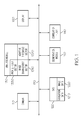
- FIG. 1 is a block diagram of one embodiment of a system for segmenting a runway
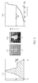
- FIG. 2 is a diagram illustrating dynamic range calibration for image enhancement
- FIG. 3 is a block diagram of one embodiment of a validation algorithm included in the image enhancement section included in the system of FIG. 1 ;
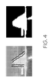
- FIG. 4 is a diagram illustrating an embodiment of a binary large object (BLOB) that represents a runway generated by the system of FIG. 1 from a captured image;
- BLOB binary large object
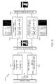
- FIG. 5 is a block diagram illustrating one embodiment of a profile filter sector included within the system of FIG. 1 ;
- FIG. 6 is a block diagram illustrating one embodiment of a comer-based segmentation algorithm included within the system of FIG. 1 ;
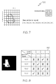
- FIG. 7 is a diagram illustrating one embodiment of a Freeman chain code
- FIG. 8 is a diagram illustrating one embodiment of a consistency matrix.
- An apparatus for locating a runway by detecting the runway coordinates and edges within data representing a region of interest (ROI) provided by a synthetic vision sensor.
- ROI region of interest
- FIG. 1 is a block diagram of one embodiment of a system 100 for segmenting a runway.
- system 100 comprises a camera 110, a synthetic vision system (SVS) database 120, an analysis module 130, a correlation filter 140, a segmentation module 150, and a display 160 coupled to one another via a bus 170 (e.g., a wired and/or wireless bus).
- a bus 170 e.g., a wired and/or wireless bus.
- Camera 110 may be any system, device, hardware (and software), or combinations thereof capable of capturing an image of region of interest (ROI) within an environment.
- camera 110 is a forward-looking camera is mounted on a vehicle (e.g., an aircraft, a spacecraft, etc.) with a predefined field of view that overlaps the same scene being surveyed by navigation data stored in SVS database 120.
- SVS database 120 is configured to store navigational data 1210 representing one or more regions of interest (ROI) including a target (e.g., a runway, a landing strip, a landing pad, and the like) that is present in the environment being surveyed by camera 110.
- SVS database 120 is further configured to provide the portion of navigational data 1210 related to an ROI where a runway (i.e., a target) is presumably present in the forward vicinity of the present location of system 100.
- SVS database 120 is also configured to store imagery data 1220 (e.g., target templates or target images) that mimics the corresponding real-world view of each target. That is, imagery data 1220 contains one or more target templates that illustrate how a target should look from one or more visual perspectives (e.g., one or more viewing angles, one or more viewing distances, etc.). SVS database 120 is further configured to provide imagery data 1220 (i.e., a template) representing the one or more visual perspectives of the target.
- imagery data 1220 e.g., target templates or target images
- SVS database 120 is configured to sort through various sources of information (not shown) related to airports, ranging, and other similar information for the present ROI. Specifically, SVS database 120 is configured to obtain the present location of system 100 from an external source (e.g., a global positioning system (GPS)) and retrieve the corresponding portions of navigational data 1210 and imagery data 1220 (e.g., runway template) for the ROI related to the present location of system 100. Once the corresponding portions of navigational data 1210 and imagery data 1220 are retrieved, the corresponding portions of navigational data 1210 and imagery data 1220, along with the images captured by camera 110, are transmitted to analysis module 130.
- GPS global positioning system
- Image Enhancement sector 1310 includes an image enhancement sector 1310, an adaptive threshold sector 1320, and a profile filter sector 1330.
- image enhancement sector 1310 comprises one or more filters (e.g., a Median Filter, a Gaussian filter with zero average, etc) to filter the noise from the captured images.
- one filter may use multi-peak histogram equalization where mid-nodes are locally determined and the affected regions (i.e. regions with contracted contrast) are substituted with generalized histogram intensities.
- Another filter may use a Kuwahara filter where a square systematic neighborhood is divided into four overlapping windows, with each window containing a central pixel that is replaced by the mean of the most homogeneous window (i.e., the window with the least standard deviation).
- image enhancement sector 1310 is configured to enhance the contrast of the captured ROI to bring uniformity into the analysis.
- image enhancement sector 1310 is configured to "stretch” the contrast (also known as, “contrast normalization”) to improve the captured image. That is, the contrast in a captured image is improved by "stretching" the range of intensity values within the predefined ROI.
- FIG. 2 shows one example of an output of image enhancement sector 1310 (via display 160).
- Portion 210 of FIG. 2 illustrates the choice of outliers and images 215, 220 illustrate the contrast enhancement, image 215 being the original image and image 220 being the filtered image.
- Portion 230 of FIG. 2 depicts a curve that represents the cumulative distribution of a normalized histogram. The data representing the ROI is enhanced by normalizing the contrast locally around the runway and its surroundings within the ROI prior to analysis.
- the captured images may include extraneous objects (e.g., a secondary runway, a taxiway, a mountainous structure beside the airport, and/or any other structure with similar sensing characteristics within the associated IR wavelength).
- profile filter sector 1330 is configured to process the captured images to generate a binary image of the ROI including a binary large object (BLOB) that can be analyzed for the presence of a runway.
- BLOB binary large object
- Profile filter sector 1330 is configured to generate a BLOB and to separate the runway from the rest of the background. To accomplish such separation, profile filter sector 1330 uses the following cues for background-foreground segmentation:
- profile filter sector 1330 is configured to depict a probability density function of the intensity data representing the ROI to segment the foreground pixels from the background pixels.
- a histogram estimator is then used to approximate the density function so that the runway BLOB is represented by a grouping of pixels in the histogram that makes up a certain percentage of the overall ROI data above the adaptive threshold.
- the percentage of the BLOB is determined from synthetic runway proportion estimates from data sets based upon the positioning of system 100 with respect to the runway coordinates and orientation perspective.
- a validation algorithm 300 determines whether a runway exists within the predefined ROI by employing one or more combinations of validation processes of the following queries:
- the threshold required to segment foreground pixels from background pixels is derived based upon the analysis of the cumulative histogram of intensities and its distribution within the ROI.
- the template size is scaled by ⁇ to account for variations in range, orientation, and synthetic noise margin.
- the binary image comprises more than one BLOB, possibly because the ROI covers more than one runway or a runway and a taxiway.
- the BLOB having a mass center that is closest to the template centroid is selected.
- profile filter sector 1330 performs an iterative binarization procedure with varied cut-off values until desired characteristics for the BLOB are obtained.
- the surface area of the BLOB is measured and the threshold is again fine tuned to match the size of the predicted template. That is, the iteration is continued until S ⁇ p - S P reaches a minimum value as shown in FIG 3 .
- system 100 uses correlation filter 140 to perform one or more filtering processes.
- the one or more filtering processes predict the expected target orientation and shape based upon the dynamics of the system and how the system is navigating (e.g., a Kalman filter approach or an approach using a like filter).
- correlation filter 140 is configured to preserve those binary pixels associated with the perspective shape of a runway presented by the runway template and its perspective orientation projection into the 2D imagery plane.
- FIG. 5 illustrates the operation of one embodiment of profile filter sector 1330.
- the process for distinguishing between the runway features and non-runway features begins by determining the center of mass of the BLOB to centralize the template on top of the BLOB (block 510).
- the major axis of the template splits the BLOB into two parts (e.g., left edges and right edges) (block 520).
- An estimate using a least square algorithm is used to identify both sides (e.g., right and left sides) of the BLOB that fits the runway profile (blocks 530, 540).
- the top and bottom corners of the BLOB are connected to form a polygon (block 550).
- BLOB profile points that are outside the polygon are considered as outlying points and are ignored.
- the resulting polygon (e.g., a quadrilateral) is a pre-estimate for the runway edges that encloses the boundaries of the true BLOB.
- Segmentation module 150 is configured to determine the appropriate boundaries for the polygon so that the polygon can be compared to the template. Determining the appropriate boundaries for the polygon for comparison to the template is important in effectively removing outliers from the BLOB profile.
- the tolerance interval (or error range) is set as a function of the ranging perspective within the captured image. For example, a relatively large error margin is preferred for effective filtering of outliers near the top edge, while a relatively small error margin is required near the bottom edge so as to accommodate effects of pixel spillage since infrared image characteristics and other shape irregularities are typically seen near the bottom edge.
- a contour includes both vertices (i.e., discontinuous edge points) and continuous edge points. Because discontinuous vertices define the limits of a contour, discontinuous vertices are the dominant points in fitting a model into a boundary. Accordingly, the corners of the BLOB are used to simplify the process of fitting a model to runway boundaries. Runway segmentation using a comer-based segmentation algorithm 600 stored in segmentation module 150 is shown in FIG. 6 .
- a contour is extracted by subjecting the BLOB with a Freeman chain code 700 (see FIG. 7 ). That is, the BLOB is initially scanned to obtain a top most pixel, which is used as a starting point for contour tracing. Starting with this pixel and moving in, for example, a clockwise direction, each pixel is assigned a code based upon its direction from the previous pixel.
- n digital points describe a closed boundary curve of a BLOB
- a region of support covering both sides of a boundary pixel is defined.
- a measure called a Cornerity Index based on statistical and geometrical properties of the pixel is defined (block 610).
- the Comerity Index indicates the prominence of a corner point (i.e., the larger the value of the comerity index of a boundary point, the stronger is the evidence that the boundary point is a corner).
- the computed comerity indices are subjected to thresholding such that only boundary pixels with strong comerity index are retained.
- the threshold is derived as a function of the region of support length to be at least ⁇ ⁇ 3 ⁇ k 10 ⁇ 2 .
- the detected corner points are portioned into four quadrants formed by the major and minor axis of the BLOB (block 620).
- the slope of the BLOB major axis is assumed to be same as that of the template and the BLOB's geometrical centroid serves as the origin.
- the next step is to form a polygon such that the polygon has maximum BLOB area coverage.
- the process of finding such a polygon is divided into two step process where the points on the left quadrants are analyzed separately from the right quadrants.
- the basic step includes populating a consistency matrix with corner candidates where slope of selected four corners are within a certain margin based on the template estimates from the navigation data (see consistency matrix 810 in FIG. 8 ).
- the selection of the corners is done in pairs by matching template slopes using two corner pairs at the left side and two corner pairs at the right side as well (block 630).
- a quadrilateral polygon with four points is selected from the consistency matrix such that they have a best fit measure with respect to the runway edges (block 640).
- the corner detection estimates are sensitive to the size of the support region. While too large of a value for a support region will smooth out fine corner points, a small value will generate a large number of unwanted corner points. If there are no corner points in any one of the quadrants, the process is reiterated to adjust the length of the region of support for conversions. After a predefined number of iterations, if the process does not converge to create at least one corner in each quadrant, a "no runway" (i.e., "no target”) report is generated.
Landscapes
- Engineering & Computer Science (AREA)
- Physics & Mathematics (AREA)
- General Physics & Mathematics (AREA)
- Theoretical Computer Science (AREA)
- Computer Vision & Pattern Recognition (AREA)
- Astronomy & Astrophysics (AREA)
- Remote Sensing (AREA)
- Multimedia (AREA)
- Image Analysis (AREA)
- Traffic Control Systems (AREA)
Applications Claiming Priority (2)
| Application Number | Priority Date | Filing Date | Title |
|---|---|---|---|
| US3190008P | 2008-02-27 | 2008-02-27 | |
| US12/336,976 US7826666B2 (en) | 2008-02-27 | 2008-12-17 | Methods and apparatus for runway segmentation using sensor analysis |
Publications (2)
| Publication Number | Publication Date |
|---|---|
| EP2096602A1 true EP2096602A1 (de) | 2009-09-02 |
| EP2096602B1 EP2096602B1 (de) | 2012-03-21 |
Family
ID=40578584
Family Applications (1)
| Application Number | Title | Priority Date | Filing Date |
|---|---|---|---|
| EP09152623A Active EP2096602B1 (de) | 2008-02-27 | 2009-02-11 | Verfahren und Vorrichtung zur Startbahnsegmentierung mittels Sensoranalyse |
Country Status (2)
| Country | Link |
|---|---|
| US (1) | US7826666B2 (de) |
| EP (1) | EP2096602B1 (de) |
Cited By (4)
| Publication number | Priority date | Publication date | Assignee | Title |
|---|---|---|---|---|
| EP2594899A3 (de) * | 2011-11-17 | 2014-10-08 | Honeywell International Inc. | Verwendung von strukturiertem Licht zum Aktualisieren von Inertialnavigationssysteme |
| EP2367152A3 (de) * | 2010-03-16 | 2016-08-31 | Honeywell International Inc. | Anzeigesysteme und Verfahren zur Anzeige verbesserter Sicht- und synthetischen Bildern |
| US9478141B2 (en) | 2011-10-28 | 2016-10-25 | Bae Systems Plc | Identification and analysis of aircraft landing sites |
| CN108364311A (zh) * | 2018-01-29 | 2018-08-03 | 深圳市亿图视觉自动化技术有限公司 | 一种金属部件自动定位方法及终端设备 |
Families Citing this family (20)
| Publication number | Priority date | Publication date | Assignee | Title |
|---|---|---|---|---|
| US8385672B2 (en) * | 2007-05-01 | 2013-02-26 | Pictometry International Corp. | System for detecting image abnormalities |
| US9262818B2 (en) | 2007-05-01 | 2016-02-16 | Pictometry International Corp. | System for detecting image abnormalities |
| FR2924831B1 (fr) * | 2007-12-11 | 2010-11-19 | Airbus France | Procede et dispositif de generation d'un ordre de vitesse de lacet pour un aeronef roulant au sol |
| US8457812B2 (en) * | 2008-06-20 | 2013-06-04 | David Zammit-Mangion | Method and system for resolving traffic conflicts in take-off and landing |
| US8914166B2 (en) | 2010-08-03 | 2014-12-16 | Honeywell International Inc. | Enhanced flight vision system for enhancing approach runway signatures |
| US9726486B1 (en) * | 2011-07-29 | 2017-08-08 | Rockwell Collins, Inc. | System and method for merging enhanced vision data with a synthetic vision data |
| US9165366B2 (en) | 2012-01-19 | 2015-10-20 | Honeywell International Inc. | System and method for detecting and displaying airport approach lights |
| US9797981B2 (en) * | 2012-03-06 | 2017-10-24 | Nissan Motor Co., Ltd. | Moving-object position/attitude estimation apparatus and moving-object position/attitude estimation method |
| EP2986940A4 (de) * | 2013-04-16 | 2017-04-05 | Bae Systems Australia Limited | Landeplatzsucher |
| AU2013245477A1 (en) * | 2013-10-16 | 2015-04-30 | Canon Kabushiki Kaisha | Method, system and apparatus for determining a contour segment for an object in an image captured by a camera |
| ES2563098B1 (es) * | 2015-06-15 | 2016-11-29 | Davantis Technologies Sl | Procedimiento de mejora de imagen IR basado en información de escena para videoanálisis |
| FR3049744B1 (fr) | 2016-04-01 | 2018-03-30 | Thales | Procede de representation synthetique d'elements d'interet dans un systeme de visualisation pour aeronef |
| US11026585B2 (en) | 2018-06-05 | 2021-06-08 | Synaptive Medical Inc. | System and method for intraoperative video processing |
| CN113544749B (zh) * | 2019-02-20 | 2025-05-02 | 三星电子株式会社 | 用于在增强现实装置上显示内容的设备和方法 |
| US12087169B2 (en) | 2020-03-04 | 2024-09-10 | Honeywell International Inc. | Methods and systems for highlighting ground traffic on cockpit displays |
| US11650057B2 (en) * | 2020-04-22 | 2023-05-16 | Honeywell International Inc. | Edge detection via window grid normalization |
| US11555703B2 (en) | 2020-04-22 | 2023-01-17 | Honeywell International Inc. | Adaptive gaussian derivative sigma systems and methods |
| CN111507287B (zh) * | 2020-04-22 | 2023-10-24 | 山东省国土测绘院 | 一种航空影像中道路斑马线角点提取方法及系统 |
| US12416929B2 (en) * | 2020-12-18 | 2025-09-16 | The Boeing Company | Landing a vertical landing vehicle |
| CN117191011A (zh) * | 2023-08-17 | 2023-12-08 | 北京自动化控制设备研究所 | 基于惯性/视觉信息融合的目标尺度恢复方法 |
Citations (1)
| Publication number | Priority date | Publication date | Assignee | Title |
|---|---|---|---|---|
| US6157876A (en) | 1999-10-12 | 2000-12-05 | Honeywell International Inc. | Method and apparatus for navigating an aircraft from an image of the runway |
Family Cites Families (6)
| Publication number | Priority date | Publication date | Assignee | Title |
|---|---|---|---|---|
| DE3830496C1 (de) * | 1988-09-08 | 1996-09-19 | Daimler Benz Aerospace Ag | Vorrichtung zum Erkennen und Verfolgen von Objekten |
| SE503679C2 (sv) * | 1994-11-18 | 1996-07-29 | Lasse Karlsen | Akustisk vindmätare |
| US5719567A (en) * | 1995-05-30 | 1998-02-17 | Victor J. Norris, Jr. | System for enhancing navigation and surveillance in low visibility conditions |
| US6606563B2 (en) * | 2001-03-06 | 2003-08-12 | Honeywell International Inc. | Incursion alerting system |
| FR2835314B1 (fr) * | 2002-01-25 | 2004-04-30 | Airbus France | Procede de guidage d'un aeronef en phase finale d'atterrissage et dispositif correspondant |
| US7113779B1 (en) * | 2004-01-08 | 2006-09-26 | Iwao Fujisaki | Carrier |
-
2008
- 2008-12-17 US US12/336,976 patent/US7826666B2/en active Active
-
2009
- 2009-02-11 EP EP09152623A patent/EP2096602B1/de active Active
Patent Citations (1)
| Publication number | Priority date | Publication date | Assignee | Title |
|---|---|---|---|---|
| US6157876A (en) | 1999-10-12 | 2000-12-05 | Honeywell International Inc. | Method and apparatus for navigating an aircraft from an image of the runway |
Non-Patent Citations (4)
| Title |
|---|
| DOEHLER H-U ET AL: "Autonomous infrared-based guidance system for approach and landing", PROCEEDINGS OF SPIE - THE INTERNATIONAL SOCIETY FOR OPTICAL ENGINEERING - ENHANCED AND SYNTHETIC VISION 2004 2004 SPIE US, vol. 5424, 2004, pages 140 - 147, XP002526939 * |
| GONG X ET AL: "A survey of techniques for detection and tracking of airport runways", COLLECTION OF TECHNICAL PAPERS - 44TH AIAA AEROSPACE SCIENCES MEETING COLLECTION OF TECHNICAL PAPERS - 44TH AIAA AEROSPACE SCIENCES MEETING 2006 AMERICAN INSTITUTE OF AERONAUTICS AND ASTRONAUTICS INC. US, vol. 23, 2006, pages 17289 - 17302, XP002526940 * |
| HAMZA ET AL.: "Augmented vision perception in infrared: algorithms and applied Systems", 2009, SPRINGER-VERLAG, pages: 243 - 267 |
| RIDA HAMZA, M IBRAHIM MOHAMED, DINESH RAMEGOWDA AND VENKATAGIRI RAO: "Runway Positioning and Moving Object Detection Prior to Landing", AUGMENTED VISION PERCEPTION IN INFRARED, 1 January 2009 (2009-01-01), Springer London, pages 244 - 269, XP009116478 * |
Cited By (5)
| Publication number | Priority date | Publication date | Assignee | Title |
|---|---|---|---|---|
| EP2367152A3 (de) * | 2010-03-16 | 2016-08-31 | Honeywell International Inc. | Anzeigesysteme und Verfahren zur Anzeige verbesserter Sicht- und synthetischen Bildern |
| US9478141B2 (en) | 2011-10-28 | 2016-10-25 | Bae Systems Plc | Identification and analysis of aircraft landing sites |
| EP2594899A3 (de) * | 2011-11-17 | 2014-10-08 | Honeywell International Inc. | Verwendung von strukturiertem Licht zum Aktualisieren von Inertialnavigationssysteme |
| CN108364311A (zh) * | 2018-01-29 | 2018-08-03 | 深圳市亿图视觉自动化技术有限公司 | 一种金属部件自动定位方法及终端设备 |
| CN108364311B (zh) * | 2018-01-29 | 2020-08-25 | 深圳市亿图视觉自动化技术有限公司 | 一种金属部件自动定位方法及终端设备 |
Also Published As
| Publication number | Publication date |
|---|---|
| US20090214080A1 (en) | 2009-08-27 |
| EP2096602B1 (de) | 2012-03-21 |
| US7826666B2 (en) | 2010-11-02 |
Similar Documents
| Publication | Publication Date | Title |
|---|---|---|
| EP2096602B1 (de) | Verfahren und Vorrichtung zur Startbahnsegmentierung mittels Sensoranalyse | |
| US10290219B2 (en) | Machine vision-based method and system for aircraft docking guidance and aircraft type identification | |
| US10255520B2 (en) | System and method for aircraft docking guidance and aircraft type identification | |
| Shen et al. | A vision-based automatic safe landing-site detection system | |
| EP2228666B1 (de) | Sichtbasiertes Fahrzeugnavigationssystem und -verfahren | |
| CN105667518B (zh) | 车道检测的方法及装置 | |
| US8537338B1 (en) | Street curb and median detection using LIDAR data | |
| Negru et al. | Image based fog detection and visibility estimation for driving assistance systems | |
| CN110502983B (zh) | 一种检测高速公路中障碍物的方法、装置及计算机设备 | |
| Nagarani et al. | Unmanned Aerial vehicle’s runway landing system with efficient target detection by using morphological fusion for military surveillance system | |
| US20210158157A1 (en) | Artificial neural network learning method and device for aircraft landing assistance | |
| CN117677976A (zh) | 可行驶区域生成方法、可移动平台及存储介质 | |
| EP2207010A1 (de) | Hauswechsel-beurteilungsverfahren und hauswechsel-beurteilungsprogramm | |
| CN104899554A (zh) | 一种基于单目视觉的车辆测距方法 | |
| CN107139666A (zh) | 越障识别系统及方法 | |
| CN113806464A (zh) | 路牙确定方法、装置、设备以及存储介质 | |
| EP4235576B1 (de) | Bestimmung des lenkwinkels eines flugzeuges | |
| Miraliakbari et al. | Automatic extraction of road surface and curbstone edges from mobile laser scanning data | |
| KR102540636B1 (ko) | 방향 정보를 포함한 지도 생성 방법 및 이를 실행하기 위하여 기록매체에 기록된 컴퓨터 프로그램 | |
| CN117423089A (zh) | 基于图像分割与雷达点云的可行驶区域拟合方法及设备 | |
| US12347204B2 (en) | Adaptive feature extraction to detect letters and edges on vehicle landing surfaces | |
| KR102540624B1 (ko) | 항공 라이다를 이용한 지도 생성 방법 및 이를 실행하기 위하여 기록매체에 기록된 컴퓨터 프로그램 | |
| KR102540629B1 (ko) | 교통 시설물에 대한 학습 데이터 생성 방법 및 이를 실행하기 위하여 기록매체에 기록된 컴퓨터 프로그램 | |
| Theuma et al. | An image processing algorithm for ground navigation of aircraft | |
| CN111611942B (zh) | 一种透视自适应车道骨架提取建库的方法 |
Legal Events
| Date | Code | Title | Description |
|---|---|---|---|
| PUAI | Public reference made under article 153(3) epc to a published international application that has entered the european phase |
Free format text: ORIGINAL CODE: 0009012 |
|
| 17P | Request for examination filed |
Effective date: 20090211 |
|
| AK | Designated contracting states |
Kind code of ref document: A1 Designated state(s): AT BE BG CH CY CZ DE DK EE ES FI FR GB GR HR HU IE IS IT LI LT LU LV MC MK MT NL NO PL PT RO SE SI SK TR |
|
| AX | Request for extension of the european patent |
Extension state: AL BA RS |
|
| R17P | Request for examination filed (corrected) |
Effective date: 20090211 |
|
| 17Q | First examination report despatched |
Effective date: 20091021 |
|
| AKX | Designation fees paid |
Designated state(s): BE DE FR GB |
|
| GRAP | Despatch of communication of intention to grant a patent |
Free format text: ORIGINAL CODE: EPIDOSNIGR1 |
|
| GRAS | Grant fee paid |
Free format text: ORIGINAL CODE: EPIDOSNIGR3 |
|
| GRAA | (expected) grant |
Free format text: ORIGINAL CODE: 0009210 |
|
| AK | Designated contracting states |
Kind code of ref document: B1 Designated state(s): BE DE FR GB |
|
| REG | Reference to a national code |
Ref country code: GB Ref legal event code: FG4D |
|
| REG | Reference to a national code |
Ref country code: DE Ref legal event code: R096 Ref document number: 602009005957 Country of ref document: DE Effective date: 20120516 |
|
| PLBE | No opposition filed within time limit |
Free format text: ORIGINAL CODE: 0009261 |
|
| STAA | Information on the status of an ep patent application or granted ep patent |
Free format text: STATUS: NO OPPOSITION FILED WITHIN TIME LIMIT |
|
| 26N | No opposition filed |
Effective date: 20130102 |
|
| REG | Reference to a national code |
Ref country code: DE Ref legal event code: R097 Ref document number: 602009005957 Country of ref document: DE Effective date: 20130102 |
|
| REG | Reference to a national code |
Ref country code: FR Ref legal event code: PLFP Year of fee payment: 8 |
|
| REG | Reference to a national code |
Ref country code: FR Ref legal event code: PLFP Year of fee payment: 9 |
|
| REG | Reference to a national code |
Ref country code: FR Ref legal event code: PLFP Year of fee payment: 10 |
|
| PGFP | Annual fee paid to national office [announced via postgrant information from national office to epo] |
Ref country code: BE Payment date: 20200225 Year of fee payment: 12 |
|
| REG | Reference to a national code |
Ref country code: BE Ref legal event code: MM Effective date: 20210228 |
|
| PGFP | Annual fee paid to national office [announced via postgrant information from national office to epo] |
Ref country code: GB Payment date: 20220222 Year of fee payment: 14 |
|
| PG25 | Lapsed in a contracting state [announced via postgrant information from national office to epo] |
Ref country code: BE Free format text: LAPSE BECAUSE OF NON-PAYMENT OF DUE FEES Effective date: 20210228 |
|
| P01 | Opt-out of the competence of the unified patent court (upc) registered |
Effective date: 20230525 |
|
| GBPC | Gb: european patent ceased through non-payment of renewal fee |
Effective date: 20230211 |
|
| PG25 | Lapsed in a contracting state [announced via postgrant information from national office to epo] |
Ref country code: GB Free format text: LAPSE BECAUSE OF NON-PAYMENT OF DUE FEES Effective date: 20230211 |
|
| PG25 | Lapsed in a contracting state [announced via postgrant information from national office to epo] |
Ref country code: GB Free format text: LAPSE BECAUSE OF NON-PAYMENT OF DUE FEES Effective date: 20230211 |
|
| PGFP | Annual fee paid to national office [announced via postgrant information from national office to epo] |
Ref country code: DE Payment date: 20260220 Year of fee payment: 18 |
|
| PGFP | Annual fee paid to national office [announced via postgrant information from national office to epo] |
Ref country code: FR Payment date: 20260224 Year of fee payment: 18 |