EP2096681A1 - Externe elektrische Verbindungsvorrichtung für elektrisch aktive Zellen eines elektrisch aktiven Paneels, wie etwa die energieerzeugenden Zellen eines Photovoltaikpaneels - Google Patents
Externe elektrische Verbindungsvorrichtung für elektrisch aktive Zellen eines elektrisch aktiven Paneels, wie etwa die energieerzeugenden Zellen eines Photovoltaikpaneels Download PDFInfo
- Publication number
- EP2096681A1 EP2096681A1 EP08300119A EP08300119A EP2096681A1 EP 2096681 A1 EP2096681 A1 EP 2096681A1 EP 08300119 A EP08300119 A EP 08300119A EP 08300119 A EP08300119 A EP 08300119A EP 2096681 A1 EP2096681 A1 EP 2096681A1
- Authority
- EP
- European Patent Office
- Prior art keywords
- external
- connector
- connection
- cells
- strips
- Prior art date
- Legal status (The legal status is an assumption and is not a legal conclusion. Google has not performed a legal analysis and makes no representation as to the accuracy of the status listed.)
- Withdrawn
Links
Images




Classifications
-
- H—ELECTRICITY
- H01—ELECTRIC ELEMENTS
- H01R—ELECTRICALLY-CONDUCTIVE CONNECTIONS; STRUCTURAL ASSOCIATIONS OF A PLURALITY OF MUTUALLY-INSULATED ELECTRICAL CONNECTING ELEMENTS; COUPLING DEVICES; CURRENT COLLECTORS
- H01R12/00—Structural associations of a plurality of mutually-insulated electrical connecting elements, specially adapted for printed circuits, e.g. printed circuit boards [PCB], flat or ribbon cables, or like generally planar structures, e.g. terminal strips, terminal blocks; Coupling devices specially adapted for printed circuits, flat or ribbon cables, or like generally planar structures; Terminals specially adapted for contact with, or insertion into, printed circuits, flat or ribbon cables, or like generally planar structures
- H01R12/70—Coupling devices
- H01R12/77—Coupling devices for flexible printed circuits, flat or ribbon cables or like structures
- H01R12/81—Coupling devices for flexible printed circuits, flat or ribbon cables or like structures connecting to another cable except for flat or ribbon cable
-
- H—ELECTRICITY
- H01—ELECTRIC ELEMENTS
- H01R—ELECTRICALLY-CONDUCTIVE CONNECTIONS; STRUCTURAL ASSOCIATIONS OF A PLURALITY OF MUTUALLY-INSULATED ELECTRICAL CONNECTING ELEMENTS; COUPLING DEVICES; CURRENT COLLECTORS
- H01R13/00—Details of coupling devices of the kinds covered by groups H01R12/70 or H01R24/00 - H01R33/00
- H01R13/66—Structural association with built-in electrical component
- H01R13/665—Structural association with built-in electrical component with built-in electronic circuit
-
- H—ELECTRICITY
- H02—GENERATION; CONVERSION OR DISTRIBUTION OF ELECTRIC POWER
- H02S—GENERATION OF ELECTRIC POWER BY CONVERSION OF INFRARED RADIATION, VISIBLE LIGHT OR ULTRAVIOLET LIGHT, e.g. USING PHOTOVOLTAIC [PV] MODULES
- H02S30/00—Structural details of PV modules other than those related to light conversion
- H02S30/10—Frame structures
-
- H—ELECTRICITY
- H02—GENERATION; CONVERSION OR DISTRIBUTION OF ELECTRIC POWER
- H02S—GENERATION OF ELECTRIC POWER BY CONVERSION OF INFRARED RADIATION, VISIBLE LIGHT OR ULTRAVIOLET LIGHT, e.g. USING PHOTOVOLTAIC [PV] MODULES
- H02S40/00—Components or accessories in combination with PV modules, not provided for in groups H02S10/00 - H02S30/00
- H02S40/30—Electrical components
- H02S40/36—Electrical components characterised by special electrical interconnection means between two or more PV modules, e.g. electrical module-to-module connection
-
- H—ELECTRICITY
- H10—SEMICONDUCTOR DEVICES; ELECTRIC SOLID-STATE DEVICES NOT OTHERWISE PROVIDED FOR
- H10F—INORGANIC SEMICONDUCTOR DEVICES SENSITIVE TO INFRARED RADIATION, LIGHT, ELECTROMAGNETIC RADIATION OF SHORTER WAVELENGTH OR CORPUSCULAR RADIATION
- H10F77/00—Constructional details of devices covered by this subclass
- H10F77/93—Interconnections
- H10F77/933—Interconnections for devices having potential barriers
- H10F77/935—Interconnections for devices having potential barriers for photovoltaic devices or modules
- H10F77/939—Output lead wires or elements
-
- Y—GENERAL TAGGING OF NEW TECHNOLOGICAL DEVELOPMENTS; GENERAL TAGGING OF CROSS-SECTIONAL TECHNOLOGIES SPANNING OVER SEVERAL SECTIONS OF THE IPC; TECHNICAL SUBJECTS COVERED BY FORMER USPC CROSS-REFERENCE ART COLLECTIONS [XRACs] AND DIGESTS
- Y02—TECHNOLOGIES OR APPLICATIONS FOR MITIGATION OR ADAPTATION AGAINST CLIMATE CHANGE
- Y02E—REDUCTION OF GREENHOUSE GAS [GHG] EMISSIONS, RELATED TO ENERGY GENERATION, TRANSMISSION OR DISTRIBUTION
- Y02E10/00—Energy generation through renewable energy sources
- Y02E10/50—Photovoltaic [PV] energy
Definitions
- the present invention relates to an external electrical connection device of the electricity generating cells of a photovoltaic panel.
- panels of panels consisting of a plurality of photovoltaic cells.
- These panels generally consist of a stack of various layers of glass, silicon, conductors and polymers.
- the silicon cells generally square, have a dimension of up to 200 mm side.
- These cells, which constitute electricity generators, are assembled in series and then glued between two sheets of glass, or between a glass sheet and various polymer layers.
- a module with a nominal voltage of 12V is generally composed of 36 (2x18) monocrystalline or polycrystalline cells in series. These assemblies of 36 cells are then assembled in parallel. In the case of a 24V module, 72 silicon cells are then used.
- Such panels or modules have a front face made of glass, directed towards the sun, for passing the radiation so that it can interact with the silicon cells and generate electricity. They also have a rear face which can be either opaque and made of a complex stack of polymers, or be transparent and, for example, consist of a glass plate. These photovoltaic modules or panels are arranged on frames that allow them to be fixed on the roofs. In addition, they are connected to each other and to an external distribution circuit for powering the uses of electricity.
- connections are made at the back of the photovoltaic panels via cable bundles extending under the panels.
- the male connector comprises a support bar of the external connection strips having a blade extending outside the photovoltaic panel, and the external connection strips are wound around the blade.
- the male connector further comprises a spacer having slots for receiving the external connection strips
- the support bar comprises a head adapted to fit on the spacer
- the spacer is glued to the edge of the photovoltaic panel.
- the blade extends outside the photovoltaic panel, perpendicularly to the surface of the photovoltaic panel.
- the means for holding the assembly is, for example, a hollow sleeve having an upper opening in which the support bar of the external connection strips is fitted.
- the periphery of the upper opening and the bar portion intended to fit into the upper opening are shaped so as to seal the junction of the sleeve and the bar.
- the bar comprises for example a peripheral bead for sealing the junction with the sleeve.
- the sleeve and the bar can be glued together.
- the sleeve comprises at each of its ends a passage for an outer connector.
- the passage for an outer connector is, for example, an indentation whose periphery comprises a groove.
- each outer connector comprises an electrical junction pallet with an external connection strip, electrically connected to an outer connection lug, and a flexible polymer material sleeve adapted to fit into the outer connector passage of the sleeve so as to to constitute a sealed closure of the passage.
- the outer connection lug of an outer connector is a male lug and the outer lug of the other outer connector is a female lug.
- junction pallet of at least one outer connector may be soldered to an external connecting strip.
- the electrical interconnection strip comprises a blade having electrical connection pads with the external strips, reversibly plugged into a lower opening of the hollow sleeve.
- the periphery of the lower opening of the sleeve and the part of the interconnection strip intended to fit into the sleeve are shaped so as to seal the junction of the sleeve and the interconnection strip.
- the male connector, the interconnection strip and the assembly holding means comprise at least one piece of plastic material.
- the electrical circuits adapted for the interconnection of the cells may comprise bypass diodes and connections for parallel or series of cells generating electricity.
- the outer connecting strips are conductive strips partially insulated by insulating layers such as enamel layers.
- the invention finally relates to an electrically active panel comprising at least one electrically active cell, equipped with an external connector according to the invention.
- the invention also relates to an electrically active panel such as a photovoltaic panel mounted in a support frame comprising four tubular hollow uprights and external connection means of the electrically active panel, whose external connection means are according to the invention and are arranged inside the hollow tubular parts of the amounts of the support frame.
- an electrically active panel such as a photovoltaic panel mounted in a support frame comprising four tubular hollow uprights and external connection means of the electrically active panel, whose external connection means are according to the invention and are arranged inside the hollow tubular parts of the amounts of the support frame.
- the external connection means comprises at least one male external connection lug and a female outer connection lug extending outside the frame and arranged such that the electrically active panels of two adjacent frames can be connected. between them by interlocking a male lug of a frame and a female lug of the other frame.
- the frame consists of at least one cut metal strip, and shaped by folding.
- the frame consists of four separate amounts assembled together.
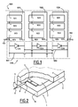
- the photovoltaic panel comprises a plurality of queues, 1010, 1020, 1030 of generating electric cells designated 1011, 1012, 1013 for the line 1010, labeled 1021, 1022, 1023, for the line 1020, and 1031, 1032, 1033 for the line 1030.
- Each of the electricity generating cells has a positive pole and a negative pole.
- the electric generating cells are connected in series, so that each queue has a negative pole connection and a positive pole connection.
- the line 1010 has a connection to the negative pole 1014 and a connection to the positive pole 1015
- the line 1020 has a connection to the negative pole 1024 and a connection to the positive pole 1025
- the line 1030 has a connection to the negative pole 1034 and a connection to the positive pole 1035.
- the set of queues is connected in parallel via a connection circuit 1200 which comprises on the one hand connections 1201 for connecting the negative poles 1014, 1024 and 1034 to a negative pole of the use circuit 1101, and a connection circuit 1202 of the positive poles 1015, 1025 and 1035 of the power generating cell lines to a positive external common connector 1102.
- the circuit of Interconnection of the power generating cell lines comprises bypass diodes 1210, 1220 and 1230 which are arranged between the negative pole and the positive pole of each of the generating cell rows. ectricity: between the negative connection 1014 and the positive connection 1015 of the power generating cell line 1010, in the same way between the negative pole 1024 and the positive pole 1025 of the line 1020, and between the negative pole 1034 and the positive pole 1035 of the queue 1030.
- Each of these diodes makes it possible to pass the queue of corresponding electric generating cells, when this queue is deteriorated or when this queue is in the shadow of a cloud, it becomes a receiver relative to the other rows of cells.
- the photovoltaic panel comprises three rows of cells generating electricity, each queue comprising three cells generating electricity.
- a photovoltaic panel may comprise a different number, and in particular a larger number of power generating cells each comprising a different number, in particular more than three electrically generating cells.
- Those skilled in the art will also understand that other connections than those just described are possible. In particular, several queues can be connected together in series instead of being in parallel.
- the photovoltaic panel generally indicated by 1, comprises at least one electrically generated cell 2 sandwiched and glued between a lower plate 3 and an upper plate 3 '.
- Each pole of the electricity generating cell 2 is connected by conduction strips 4 (only one visible in the figure) which, for those intended to be connected to the outside of the panel, are connected to a connection strip.
- 5 external connecting strip consists of a ribbon 6 of conductive material such as copper, a part of the surface of which is isolated for example by an enamel layer 9, and one end 7 is welded on the conductive strips 4 so as to provide an electrical connection and whose end 8 located towards the outside of the panel, is bare, so as to ensure electrical contact with a connection means.
- the external connection strip which is disposed at the interface between the lower and upper layers of the photovoltaic panel extends outwardly of the wafer 1A thereof.
- a panel which includes a plurality of power generating cell lines may include an external connection strip for the positive pole of each line of cells generating electricity and an external connection strip for the negative pole of each row of cells generators of electricity.
- a photovoltaic panel comprising three rows of cells generating electricity may comprise at least four external connection strips extending outwardly of the edge of the photovoltaic panel, depending on the type of connection chosen by the photovoltaic panel manufacturer. and may, for example, have six as shown in the drawing.
- each queue (commonly called "string") can be connected to the others outside the panel. There are then six test strips.
- the external electrical connection device shown at figure 3 comprises a male connector generally marked by 100, fixed on the wafer 1A of the photovoltaic panel 1, an electrical interconnection strip of the external strips generally marked 160, a first external contactor comprising an electrical junction means with the external connection strips connected to a first polarity of electrically generating cells generally denoted by 180, a second external connector comprising an electrical junction means with an external connection strip connected to a second polarity of electrically generating cells generally identified by 190, and finally means for holding and assembling the male connector, the interconnection strip, the first and the second external connector.
- This holding and assembling means is generally indicated by 140.
- This male connector firstly comprises a spacer 110 bonded against the wafer 1 A of the photovoltaic panel. As shown in figure 4 this spacer has slots 112 which serve to receive the strips 5 coming out of the slice 1A of the photovoltaic panel.
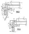
- This spacer 110 serves to maintain a strip support strip 120 (see figures 3 , 4 ; 5 6 ) which has a fixing head 121 and a blade 122 extending outwardly of the panel perpendicular thereto.
- the blade 122 has grooves 126 intended to receive strips 5.
- the head 120 of the bar has a groove 122 intended to fit on the spacer 110 bonded to the edge of the photovoltaic panel.
- the head also comprises a blade 124 which is intended to come into contact with the lower part of the photovoltaic panel.
- This lower blade 124 comprises an opening 125 intended to let the external connection strips 5.
- This opening 125 is of sufficient size so that, at the time of assembly, the strips 5 can pass through this opening and that, after installation strips, the bar can be put permanently in position being close to the edge of the photovoltaic panel, as shown in Figures 5 and 6 .
- the strips 5 are disposed inside the grooves and wound around the blade 122 for supporting the strips.
- the end of each strip being taken up in a cavity 129 located at the junction between the blade 122 and the support head 121 of the bar 120.
- This cavity 129 has edges 130 which can be folded to maintain in position conductive strips 5, 5 ', 5''These edges can be folded for example by ultrasound
- the connector comprises a base 128 intended to fit into the holding sleeve 140.
- This base 128 comprises a bead 127 which extends at its periphery and which is intended to ensure tightness during mounting of the male connector in its support, thus obtaining a male connector which comprises a connection blade extending outwardly of the photovoltaic panel and around which the conductive strips are wound and can thus come into contact with pads.
- the male connector is intended to be inserted into a holding device of the assembly generally identified by 140, which is a hollow sleeve, having an upper opening 142 intended to receive the male connector and a lower opening 143 in which will be inserted the electrical interconnection bar 160 which will be described later.
- the sleeve 140 comprises a body 141 of generally rectangular shape, the two ends of which have notches of generally semicircular shape 144 and 145 which will be intended to receive the external connectors 180 and 190.
- the side walls 146 of the sleeve 140 are reinforced by ribs 147 and at their lower part, have small hooks 149 which are intended to retain the interconnection bar 160.
- the semicircular notches 144 and 145 for receiving the outer connectors comprise grooves 150 and 151 in which may be s' insert seals associated with the external connectors.
- the external electrical connection device comprises two outer connectors generally marked by 180 and 190
- the first outer connector 180 comprises an electrical junction pallet 181 which is a plate of copper material which can be covered with a brazing paste.
- This electrical junction pallet is connected by an electrical conductor 183 to an outer connection lug 182 which is for example a female connection lug.
- the conducting wire 183 passes through a sleeve of flexible polymer material 184 whose shape is adapted to fit into the notch 144 of the sleeve 140.
- the edge of the sleeve of polymer material 184 is adapted to be inserted into the groove 150 which extends at the periphery of the notch 144 of the retaining sleeve 140, so as to seal.
- the second outer connector 190 includes an electrical junction pallet 191 also made of copper alloy on which a brazing paste is deposited.
- the electrical junction pallet is connected to an outer connection lug 192 which is a male lug via an electrical conductor 193 which passes through the sleeve 194 of flexible polymer material adapted to fit into the notch 145 of the retaining sleeve 140.
- the edge of the sleeve 194 is adapted to fit into the groove 151 which extends to the periphery of notch 145 so as to ensure a good seal.
- the joining pallets 181 and 191 come into contact with the strips 5 'and 5 " located at the ends of the blade 122 of the male connector 100.
- the joining pallets 181 and 191 are in contact strips connection, they can be welded for example by induction heating from the outside, the induction heating melting solder paste and thus ensuring the brazing of the connecting pallets on the connecting strips.
- junction pallets consisting of lamellar contacts which make it possible to make connections without brazing.
- the sealing of the connector of the assembly is provided on the one hand by the flexible polymer material sleeves 184 and 194 of the outer connectors, and on the other hand part, by the beads 127 which are at the upper part of the blade of the male connector and which come into contact with the periphery of the opening 142 of the retaining sleeve 140.
- the shape of the opening 142 of the sleeve 140 is adapted so that there is a good fit of the male connector in the holding sleeve 140 so as to provide excellent sealing.
- the male connector can be glued to the upper part of the retaining sleeve 140.
- the electrical connection device also comprises an electrical interconnection strip of the outer strips, generally marked 160, which comprises a central blade 161 having junction pads 165 arranged to come into contact with each other. interconnecting strips 5, 5 ', 5 "of the blade of the male connector, this blade 161 of the electrical interconnection strip comprises at its bottom part sealing beads 162, and a base 163 having openings 164.
- the electrical interconnection strip is plugged into the opening 143 located at the bottom of the retaining sleeve 140, the blade 161 coming opposite the blade 122 of the male connector so that the electrical junction pads 165 come in contact with the external connection strips 5, 5 'and 5 ".
- the hooks 149 disposed at the bottom of the retaining sleeve 140 snap into the holes 164 provided in the base 163 of the interconnection bar.
- the beads 162 located at the base of the interconnection strip come into contact with the side walls of the sleeve 140 and thus provide sealing.
- the interconnection strip comprises electrical interconnection circuits of the different rows of electricity generating cells of the photovoltaic panel, corresponding, for example, to the electrical diagram shown in FIG. figure 1 .
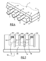
- These electrical circuits which are overmolded inside the blade 161 may comprise, as shown in FIG. figure 7 , diodes 166 which provide the bipassage between the pads 165A and 165B which are connected on the one hand to the negative and positive poles respectively of the rows of cells generating electricity and on the other hand may also contain interconnections 167 between the pads 165A contacting the negative poles of the rows of cells generating electricity, and interconnections 168 between pads 165B intended to come into contact with the connectors of the positive poles of the rows of cells producing electricity.
- This interconnection bar is removably mounted in the holding sleeve so that it can be changed to replace these bars when components such as the diodes have been damaged.
- connection strip makes it possible to change the diodes of the photovoltaic module without inadvertently touching the electrically active parts of the photovoltaic module.
- This interconnection strip also makes it possible to perform the different types of connections of the generating cell lines of electricity outside the photovoltaic module, according to the decision of the manufacturer of photovoltaic modules.
- connection device of a photovoltaic panel is, with the exception of conductive elements, consisting of molded plastic parts.
- This plastic material may, optionally, be chosen so as to have good thermal conductivity.
- the external connection device which has just been described, is fixed on the edge of the photovoltaic panels and can be adapted to be able to be installed for example in the amount of the support frames of the photovoltaic panels. It can also be fixed on the amount of aluminum angles currently used.
- the external connection device which has just been described is fixed on the edge of the photovoltaic panels. But, it can be adapted to be used in replacement of the current connection devices of the photovoltaic modules for which the connection strips open on the rear face of the photovoltaic panels. The skilled person knows how to make such an adaptation.
- the interconnection device makes it possible to connect to the outside a photovoltaic panel comprising three rows of cells generating electricity. But one skilled in the art will understand that he can adapt this interconnection device to photovoltaic panels which comprise a larger or smaller number of photocell queues.
- the connector is mounted on a photovoltaic panel whose active cells are cells generating electricity.
- Such connectors can be mounted on any type of electrically active panel having electrically active cells.
- the electrically active device may be a generator such as photovoltaic cells or an electrical receiver such as a liquid crystal screen panel (LCD), organic electroluminescent panels, display panels such as plasma screens.
- a generator such as photovoltaic cells
- an electrical receiver such as a liquid crystal screen panel (LCD), organic electroluminescent panels, display panels such as plasma screens.
- LCD liquid crystal screen panel
- organic electroluminescent panels such as organic electroluminescent panels
- display panels such as plasma screens.
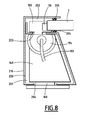
- Such electrically active panels 1 are mounted in rectangular frames 200 comprising four hollow amounts 210, 211, 212, 213. Each amount whose section has, for example, the shape visible to the figure 8 , comprises a hollow tubular portion 201 of trapezoidal section, surmounted by a groove 202 intended to receive the edge of the electrically active panel 1.
- Such amounts can be manufactured by various methods known to those skilled in the art, but preferably by folding a metal strip of suitable thickness to obtain sufficient rigidity and mechanical strength. These strips are preferably made of stainless steel, but any suitable material known to those skilled in the art can be used. In general, the amounts are manufactured separately and assembled for example by welding, so as to constitute a frame. However, especially when the amounts are manufactured by folding metal strips, two, three or four amounts can be made by folding a single band previously cut in a suitable manner.
- the connectors according to the invention are arranged in the uprights so as to be maintained and protected while allowing electrical connections to the once inside the hollow parts of the frame and outwardly to connect the active cells 2 of the panel and to connect the panels together or with a circuit 7 of use.
- a connection device of a photovoltaic panel is inserted in the amount 210 of a frame 200 which receives in a groove 202, the edge of the photovoltaic panel 1.
- connection device comprises, in accordance with what has been described above, a male connector 100, an interconnection bar 160, external connectors and a holding means 140 of the male connector 100, the interconnection bar 160 and external connectors (in the figure we see only the sleeve 194 of a single outer connector).
- the holding means 140 is a hollow sleeve disposed inside 201 of the tubular part of the upright 210 of the frame 200, facing, on the one hand, an opening 203 formed in the upper part of the tubular part of the upright 201 , and a cover 204 formed in the lower part of the tubular portion of the upright 201.
- the male connector 100 which is mounted on the edge of the photovoltaic panel 1, via a spacer 110, penetrates inside the hollow portion 201 of the upright 210 passing through the upper opening 203 and thus , is inserted inside the hollow sleeve 140.
- the interconnection bar 160 penetrates inside the hollow portion 201 of the upright 210 passing through the lower opening 204 and, thus, is inserted inside the hollow sleeve 140 holding .
- an external connector of the male type comprises a conductor 193 which leaves the hollow holding sleeve 140 through the flexible sleeve 194 which connects an electric function pallet (not visible on the figure 9 ) disposed inside the hollow holding sleeve 140 and an outer male connection lug 192.
- the external connection lug which extends outside the upright 210 of the frame 200 comprises a base 192 'which passes through an opening provided in the side wall of the upright 210, and which cooperates with a retaining spacer 292, disposed in the upright 201.
- the male lug is oriented upwards.
- a female lug 182 extends outside the post to cooperate with a holding spacer 282 and with an electrical conductor (not visible in the figure).
- This female lug is oriented downwards so as to cooperate with a male lug of an adjacent frame and thus allow the interconnection of adjacent panels.
- the amount of the frame comprises, at its upper part, a wing 206 which extends outwardly and which ensures the seal at the junction between two panels adjacent.
- the male terminal is oriented upwards and the female terminal down, but the reverse arrangement is possible.
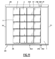
- the frame 200 which supports the panel 1 of photovoltaic cells 2 comprises external male connectors 214A, 215A, 216A located on a first upright 210 which contains the external electrical connection device (not visible in the figure) of the photovoltaic cells, and female external connectors 214B, 215B, 216B and 217, located on a second post 212 of the frame, opposite the first post 210.
- the male connectors 214A, 215A and 216A, and the female connectors 214B, 215B and 216C are arranged so as to be facing each other two by two.
- the male connectors of one can cooperate with the female connectors of the other.
- the male and female connectors are connected either to the external connection device or to each other, according to their destination, via electrical conductors which are received in the hollow parts of the frame 200.
- the electrical conductors are at the protected and concealed.
- the number of external connectors and the electrical connections between them can be adapted according to the needs of each application and the skilled person knows to determine the appropriate connections.
- connections for the return circuits will include, for each frame, a male outer connector and a female outer connector directly connected by an electrical conductor disposed within the frame of the amounts.
- connection means except the pods which must extend outside the amounts, are completely contained inside the amounts.
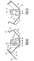
- FIG. 12 To the figure 12 is shown in section an amount 210 receiving a female outer connector 182 in a first phase of manufacture.
- the amount 210 consists of a metal strip which has been partially folded so as to give it a certain rigidity while constituting an open structure.
- This amount comprises a bottom 217 pierced with a hole 218 for receiving a stud 283 for fixing the spacer 282 which supports the female lug 182 of the outer female connector.
- the amount 212 also includes an outer side face 219 and an inner side face 222.
- the outer side face 219 carries an outer wing 206, an inner wing 220 and a connecting tab 221.
- the outer wing 206 is intended to seal at the junction between two adjacent frames.
- the inner wing 220 is intended to cover the edge of the photovoltaic panel held in the frame.
- the tab 221 serves to ensure the junction between two adjacent amounts.
- the inner side face 222 is extended by a flange 223 having a flange 224, which are intended to form the upper wall of the tubular portion of the upright and thus constitute the lower face of the groove for receiving the edge of the photovoltaic panel.
- the flange 224 is adapted to be welded to the outer side face 219 at the end of mounting of the upright.
- the inner side face 222 is further extended by at least one connecting lug 225 which serves to ensure the junctions with an adjacent amount.
- the amount is open which allows to have inside a spacer 282 which carries a female terminal outer connection 182.
- the spacer 282 which is made of plastic material has at its lower part an attachment stud 283 which is inserted into the hole 218 of the lower face 217 of the upright. At its upper part, the spacer 282 has a lug 284 which allows to retain the inner side face 222 by clipping the flange 223.
- the outer side face 219 has an opening not visible in the figure, allowing the passage of the outer connection lug.
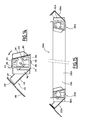
- a spacer 300 which is implanted for example in the amount 213 disposed between the uprights 210 and 212 which carry the connecting devices.
- the spacer 300 which is only intended to retain the electrical connection conductors comprises a central opening 301 intended to receive the electrical conductors, a fixing stud 302 on its lower face and a lug 303 for clipping the wings of the upright 213 on its upper side.
- the amount 211 comprises a bottom 230 framed by an outer side face 231 and an inner side face 232.
- the amount differs from that previously described only in that it does not comprise an outer wing intended to provide the sealing at the junction between two adjacent frames, nor opening to pass the outer connection lug.
- connection means and the holding struts of the electrical connection conductors are arranged on the metal strips intended to constitute the amounts of the frame, these strips are arranged side by side in a disposition corresponding to the unfolded frame and the conductors are put in place. electrical junction to form the internal electrical circuits of the frame.
- the bending of the internal lateral faces of the uprights is finished so as to envelop the connecting devices or the spacers arranged on the metal strips intended to constitute the uprights and thus to clip the internal lateral faces on the lugs. clipping.
- the inner side face 222 of the amount is completely folded and that it surrounds the spacer 282 on which it is held by clipping through the lug 284.
- the outer side face 219 is still in the open position.
- the four uprights are then folded to form a rectangular frame which is assembled by welding the fastening tabs such as the fastening tab 225 provided on the inner lateral faces of the adjacent uprights.
- FIG. Fig. 15 A 200 A frame is thus obtained, as shown in FIG. Fig. 15 , the outer side faces of the uprights are in the open position, spaced outwardly.
- the side faces 220A and 222A of the uprights 210A and 212A in the open position.
- the photovoltaic panel is placed on the upright of the frame, it is possible to continue the assembly by folding the outer lateral faces, in particular the external lateral faces 220A, 222A visible in the figure, towards the inside of the frame as it is represented on the figure 17 , and ending by welding including the fastening tabs of the outer lateral faces of the uprights on the adjacent uprights, and the four upper and lower corners of the uprights 210, 211, 212, 213.
- the photovoltaic panel is thus mounted on a frame that incorporates the connection means in its tubular uprights.
Landscapes
- Engineering & Computer Science (AREA)
- Microelectronics & Electronic Packaging (AREA)
- Photovoltaic Devices (AREA)
- Organic Low-Molecular-Weight Compounds And Preparation Thereof (AREA)
Priority Applications (18)
| Application Number | Priority Date | Filing Date | Title |
|---|---|---|---|
| EP08300119A EP2096681A1 (de) | 2008-02-27 | 2008-02-27 | Externe elektrische Verbindungsvorrichtung für elektrisch aktive Zellen eines elektrisch aktiven Paneels, wie etwa die energieerzeugenden Zellen eines Photovoltaikpaneels |
| KR1020107020668A KR101590133B1 (ko) | 2008-02-27 | 2009-02-25 | 태양광 패널의 발전용 전지와 같은 전기 활성 패널의 전기 활성 전지의 외부 전기 접속용 장치 |
| US12/919,682 US8714998B2 (en) | 2008-02-27 | 2009-02-25 | Device for the external electrical connection of electrically active cells of an electrically active panel |
| EP09719958.2A EP2257995B1 (de) | 2008-02-27 | 2009-02-25 | Vorrichtung für den externen elektrischen anschluss der unter spannung stehenden zellen eines unter spannung stehenden panels, wie etwa stromerzeugende zellen eines photovoltaikmoduls |
| MX2010009495A MX2010009495A (es) | 2008-02-27 | 2009-02-25 | Dispositivo de conexion electrica externo de celdas electricamente activas de un panel electricamente activo, tales como las celdas generadoras de electricidad de un panel fotovoltaico. |
| EA201101239A EA019620B1 (ru) | 2008-02-27 | 2009-02-25 | Устройство внешнего электрического соединения электрически активных элементов электрически активной панели, таких как электрогенерирующие элементы фотоэлектрической панели |
| EA201001374A EA016004B1 (ru) | 2008-02-27 | 2009-02-25 | Устройство внешнего электрического соединения электрически активных элементов электрически активной панели, таких как электрогенерирующие элементы фотоэлектрической панели |
| CN2009801137742A CN102007605B (zh) | 2008-02-27 | 2009-02-25 | 用于诸如光电面板的发电单元的电活性面板的电活性单元的外部电连接的设备 |
| CA2718094A CA2718094C (en) | 2008-02-27 | 2009-02-25 | Device for the external electrical connection of electrically active cells of an electrically active panel |
| BRPI0908482A BRPI0908482A2 (pt) | 2008-02-27 | 2009-02-25 | dispositivo de conexão elétrica externa das células eletricamente ativadas de um painel eletricamente ativo, tais como as células geradoras de eletricidade de um painel fotovoltaico |
| JP2010548152A JP4964991B2 (ja) | 2008-02-27 | 2009-02-25 | 光電池パネルの発電セルのような電気活性パネルの電気活性セルにおける外部電気接続用デバイス |
| PCT/FR2009/050302 WO2009112762A2 (fr) | 2008-02-27 | 2009-02-25 | Dispositif de connexion électrique externe des cellules électriquement actives d'un panneau électriquement actif, telles que les cellules génératrices d'électricité d'un panneau photovoltaïque |
| AU2009224449A AU2009224449B2 (en) | 2008-02-27 | 2009-02-25 | Device for the external electrical connection of electrically active cells of an electrically active panel, such as electricity-generating cells of a photovoltaic panel |
| IL207820A IL207820A0 (en) | 2008-02-27 | 2010-08-26 | Device for the external electrical connection of electrically active cells of an electrically active panel, such as electricity-generating cells of a photovoltaic panel |
| MA33128A MA32113B1 (fr) | 2008-02-27 | 2010-08-26 | Dispositif de connexion électrique externe des cellules électriquement actives d'un panneau électriquement actif, telles que les cellules génératrices d'électricité d'un panneau photovoltaïque |
| ZA2010/06129A ZA201006129B (en) | 2008-02-27 | 2010-08-27 | Device for the external electrical connection of electrically active cells of an electrically active panel such as electricity-generating cells of a photovoltaic panel |
| EG2010081444A EG25897A (en) | 2008-02-27 | 2010-08-29 | Device for the external electrical connection of electrically active cells of an electrically activepanel, such as electricity-generating cells of a photovoltaic panel |
| JP2011283601A JP2012060193A (ja) | 2008-02-27 | 2011-12-26 | 光電池パネルの発電セルのような電気活性パネルの電気活性セルにおける外部電気接続用デバイス |
Applications Claiming Priority (1)
| Application Number | Priority Date | Filing Date | Title |
|---|---|---|---|
| EP08300119A EP2096681A1 (de) | 2008-02-27 | 2008-02-27 | Externe elektrische Verbindungsvorrichtung für elektrisch aktive Zellen eines elektrisch aktiven Paneels, wie etwa die energieerzeugenden Zellen eines Photovoltaikpaneels |
Publications (1)
| Publication Number | Publication Date |
|---|---|
| EP2096681A1 true EP2096681A1 (de) | 2009-09-02 |
Family
ID=39561943
Family Applications (2)
| Application Number | Title | Priority Date | Filing Date |
|---|---|---|---|
| EP08300119A Withdrawn EP2096681A1 (de) | 2008-02-27 | 2008-02-27 | Externe elektrische Verbindungsvorrichtung für elektrisch aktive Zellen eines elektrisch aktiven Paneels, wie etwa die energieerzeugenden Zellen eines Photovoltaikpaneels |
| EP09719958.2A Active EP2257995B1 (de) | 2008-02-27 | 2009-02-25 | Vorrichtung für den externen elektrischen anschluss der unter spannung stehenden zellen eines unter spannung stehenden panels, wie etwa stromerzeugende zellen eines photovoltaikmoduls |
Family Applications After (1)
| Application Number | Title | Priority Date | Filing Date |
|---|---|---|---|
| EP09719958.2A Active EP2257995B1 (de) | 2008-02-27 | 2009-02-25 | Vorrichtung für den externen elektrischen anschluss der unter spannung stehenden zellen eines unter spannung stehenden panels, wie etwa stromerzeugende zellen eines photovoltaikmoduls |
Country Status (15)
| Country | Link |
|---|---|
| US (1) | US8714998B2 (de) |
| EP (2) | EP2096681A1 (de) |
| JP (2) | JP4964991B2 (de) |
| KR (1) | KR101590133B1 (de) |
| CN (1) | CN102007605B (de) |
| AU (1) | AU2009224449B2 (de) |
| BR (1) | BRPI0908482A2 (de) |
| CA (1) | CA2718094C (de) |
| EA (2) | EA019620B1 (de) |
| EG (1) | EG25897A (de) |
| IL (1) | IL207820A0 (de) |
| MA (1) | MA32113B1 (de) |
| MX (1) | MX2010009495A (de) |
| WO (1) | WO2009112762A2 (de) |
| ZA (1) | ZA201006129B (de) |
Cited By (2)
| Publication number | Priority date | Publication date | Assignee | Title |
|---|---|---|---|---|
| WO2018049245A1 (en) * | 2016-09-09 | 2018-03-15 | Cruz Paul Martin | Wire tensioning system |
| WO2019135031A2 (fr) | 2018-01-08 | 2019-07-11 | Jean Pierre Reyal | Système d'installation de façades et de toitures végétales, étanche a l'eau, et compatible avec l'installation de modules photovoltaïques |
Families Citing this family (8)
| Publication number | Priority date | Publication date | Assignee | Title |
|---|---|---|---|---|
| US9450130B2 (en) * | 2011-01-27 | 2016-09-20 | Sunpower Corporation | Frame-mounted wire management device |
| WO2012120489A1 (en) * | 2011-03-08 | 2012-09-13 | Kingspan Research And Developments Limited | A composite insulating panel |
| FR2996802B1 (fr) * | 2012-10-12 | 2014-11-21 | Saint Gobain | Vitrage feuillete |
| PL3304727T3 (pl) | 2015-05-26 | 2022-01-17 | Arcelormittal | Elektryczne urządzenie przyłączeniowe dla systemów fotowoltaicznych |
| HUE056082T2 (hu) | 2015-05-26 | 2022-01-28 | Arcelormittal | Elektromos csatlakoztató eszköz fotovoltaikus rendszerhez |
| US20180006602A1 (en) * | 2016-07-01 | 2018-01-04 | Sunpower Corporation | Photovoltaic module having an external electrical connector |
| JP7325199B2 (ja) * | 2019-03-20 | 2023-08-14 | 株式会社カネカ | 太陽電池モジュール、修復済み太陽電池モジュール、及び太陽電池モジュールの修復方法 |
| CN110288916B (zh) * | 2019-07-11 | 2021-08-24 | 昆山工研院新型平板显示技术中心有限公司 | 支撑构件和柔性显示装置 |
Citations (3)
| Publication number | Priority date | Publication date | Assignee | Title |
|---|---|---|---|---|
| US4310211A (en) * | 1979-12-26 | 1982-01-12 | Amp Incorporated | High current contact system for solar modules |
| EP1120837A2 (de) * | 2000-01-24 | 2001-08-01 | Sumitomo Wiring Systems, Ltd. | Solarzellenpaneel |
| WO2007118798A2 (de) * | 2006-04-13 | 2007-10-25 | Weidmüller Interface GmbH & Co. KG | Elektrische anschlussvorrichtung für flachleiter |
Family Cites Families (9)
| Publication number | Priority date | Publication date | Assignee | Title |
|---|---|---|---|---|
| AU608701B2 (en) * | 1988-04-11 | 1991-04-11 | Ebara Solar, Inc. | Integral frame and junction box for a photovoltaic module |
| JP3679611B2 (ja) * | 1998-06-05 | 2005-08-03 | 三洋電機株式会社 | 太陽電池モジュール |
| JP2000040547A (ja) * | 1998-07-22 | 2000-02-08 | Sumitomo Wiring Syst Ltd | 電気接続用コネクタ |
| JP2001144315A (ja) * | 1999-11-15 | 2001-05-25 | Sumitomo Wiring Syst Ltd | 太陽電池パネル用のコネクタ及びそのコネクタを用いた配線接続部の構造 |
| JP2001148493A (ja) * | 1999-11-19 | 2001-05-29 | Sumitomo Wiring Syst Ltd | 太陽電池パネル用のコネクタ装置 |
| JP4069834B2 (ja) * | 2003-08-20 | 2008-04-02 | 松下電工株式会社 | 太陽光発電システム |
| JP4681806B2 (ja) * | 2003-12-19 | 2011-05-11 | キヤノン株式会社 | 太陽電池モジュール |
| JP2009542014A (ja) * | 2006-06-29 | 2009-11-26 | フーバー + スーナー アーゲー | コネクションボックス |
| CN101990712A (zh) * | 2007-12-21 | 2011-03-23 | 纳幕尔杜邦公司 | 光伏阵列和方法 |
-
2008
- 2008-02-27 EP EP08300119A patent/EP2096681A1/de not_active Withdrawn
-
2009
- 2009-02-25 AU AU2009224449A patent/AU2009224449B2/en not_active Ceased
- 2009-02-25 MX MX2010009495A patent/MX2010009495A/es active IP Right Grant
- 2009-02-25 BR BRPI0908482A patent/BRPI0908482A2/pt not_active Application Discontinuation
- 2009-02-25 CA CA2718094A patent/CA2718094C/en not_active Expired - Fee Related
- 2009-02-25 CN CN2009801137742A patent/CN102007605B/zh not_active Expired - Fee Related
- 2009-02-25 JP JP2010548152A patent/JP4964991B2/ja active Active
- 2009-02-25 EA EA201101239A patent/EA019620B1/ru not_active IP Right Cessation
- 2009-02-25 EP EP09719958.2A patent/EP2257995B1/de active Active
- 2009-02-25 US US12/919,682 patent/US8714998B2/en not_active Expired - Fee Related
- 2009-02-25 WO PCT/FR2009/050302 patent/WO2009112762A2/fr not_active Ceased
- 2009-02-25 KR KR1020107020668A patent/KR101590133B1/ko not_active Expired - Fee Related
- 2009-02-25 EA EA201001374A patent/EA016004B1/ru not_active IP Right Cessation
-
2010
- 2010-08-26 MA MA33128A patent/MA32113B1/fr unknown
- 2010-08-26 IL IL207820A patent/IL207820A0/en unknown
- 2010-08-27 ZA ZA2010/06129A patent/ZA201006129B/en unknown
- 2010-08-29 EG EG2010081444A patent/EG25897A/xx active
-
2011
- 2011-12-26 JP JP2011283601A patent/JP2012060193A/ja active Pending
Patent Citations (3)
| Publication number | Priority date | Publication date | Assignee | Title |
|---|---|---|---|---|
| US4310211A (en) * | 1979-12-26 | 1982-01-12 | Amp Incorporated | High current contact system for solar modules |
| EP1120837A2 (de) * | 2000-01-24 | 2001-08-01 | Sumitomo Wiring Systems, Ltd. | Solarzellenpaneel |
| WO2007118798A2 (de) * | 2006-04-13 | 2007-10-25 | Weidmüller Interface GmbH & Co. KG | Elektrische anschlussvorrichtung für flachleiter |
Cited By (2)
| Publication number | Priority date | Publication date | Assignee | Title |
|---|---|---|---|---|
| WO2018049245A1 (en) * | 2016-09-09 | 2018-03-15 | Cruz Paul Martin | Wire tensioning system |
| WO2019135031A2 (fr) | 2018-01-08 | 2019-07-11 | Jean Pierre Reyal | Système d'installation de façades et de toitures végétales, étanche a l'eau, et compatible avec l'installation de modules photovoltaïques |
Also Published As
| Publication number | Publication date |
|---|---|
| EG25897A (en) | 2012-10-03 |
| US8714998B2 (en) | 2014-05-06 |
| EA201101239A1 (ru) | 2012-02-28 |
| CN102007605B (zh) | 2013-01-02 |
| CA2718094C (en) | 2017-12-19 |
| ZA201006129B (en) | 2011-06-29 |
| AU2009224449A1 (en) | 2009-09-17 |
| JP4964991B2 (ja) | 2012-07-04 |
| WO2009112762A3 (fr) | 2010-08-26 |
| KR20100133981A (ko) | 2010-12-22 |
| CN102007605A (zh) | 2011-04-06 |
| EP2257995A2 (de) | 2010-12-08 |
| MA32113B1 (fr) | 2011-02-01 |
| BRPI0908482A2 (pt) | 2018-11-06 |
| AU2009224449B2 (en) | 2015-03-12 |
| US20110041896A1 (en) | 2011-02-24 |
| WO2009112762A2 (fr) | 2009-09-17 |
| EA019620B1 (ru) | 2014-05-30 |
| KR101590133B1 (ko) | 2016-01-28 |
| CA2718094A1 (en) | 2009-09-17 |
| IL207820A0 (en) | 2010-12-30 |
| EA016004B1 (ru) | 2012-01-30 |
| JP2011513963A (ja) | 2011-04-28 |
| EP2257995B1 (de) | 2019-02-20 |
| EA201001374A1 (ru) | 2011-04-29 |
| MX2010009495A (es) | 2011-02-24 |
| JP2012060193A (ja) | 2012-03-22 |
Similar Documents
| Publication | Publication Date | Title |
|---|---|---|
| EP2257995B1 (de) | Vorrichtung für den externen elektrischen anschluss der unter spannung stehenden zellen eines unter spannung stehenden panels, wie etwa stromerzeugende zellen eines photovoltaikmoduls | |
| EP2143149B1 (de) | Tragerahmen für eine elektrisch aktive tafel, z. b. eine photovoltaische tafel | |
| CA2684545C (fr) | Bati support d'un panneau tel que panneau photoelectrique et paroi exterieure d'un batiment comportant de tels batis | |
| FR2696280A1 (fr) | Batterie multicellulaire compacte. | |
| FR2922366A1 (fr) | Perfectionnements apportes a des elements capables de collecter de la lumiere | |
| WO2013032802A1 (en) | Photovoltaic module | |
| FR2941565A1 (fr) | Unite photovoltaique de recuperation d'energie et ensemble photovoltaique comprenant une telle unite. | |
| EP1586122B1 (de) | Photovoltaisches modul mit aussenanschlussklemmen | |
| ES2705200T3 (es) | Módulo de célula solar | |
| EP3549256B1 (de) | Elektrische verbindungsvorrichtung für ein fotovoltaiksystem | |
| EP3334033A1 (de) | Fotovoltaikmodul und platte aus miteinander verbundenen fotovoltaikmodulen | |
| FR3130452A1 (fr) | Module photovoltaïque à diode de dérivation imprimée intégrée | |
| JP2008283035A (ja) | 太陽電池モジュール | |
| EP3459121B1 (de) | Anordnung aus fotovoltaischen zellen | |
| WO2003038911A1 (fr) | Assemblage de cellules photovoltaiques et procede de fabrication d'un tel assemblage | |
| FR2704629A1 (fr) | Film chauffant à structure modulaire, pour chauffage par rayonnement, et dispositif pour sa connexion. | |
| WO2004075304A1 (fr) | Procede de realisation d’un module photovoltaique et module photovoltaique realise par ce procede | |
| CN218602448U (zh) | 一种太阳能叶形结构 | |
| FR2502400A1 (fr) | Perfectionnement aux panneaux de photopiles solaires | |
| IT201800009650A1 (it) | Pannello fotovoltaico e relativo metodo di produzione. | |
| WO2011098722A2 (fr) | Ensemble de support et de raccordement électrique pour une cellule photovoltaïque à contacts arrière, module photovoltaïque comprenant un tel ensemble et procédé de fabrication d'un tel module |
Legal Events
| Date | Code | Title | Description |
|---|---|---|---|
| PUAI | Public reference made under article 153(3) epc to a published international application that has entered the european phase |
Free format text: ORIGINAL CODE: 0009012 |
|
| AK | Designated contracting states |
Kind code of ref document: A1 Designated state(s): AT BE BG CH CY CZ DE DK EE ES FI FR GB GR HR HU IE IS IT LI LT LU LV MC MT NL NO PL PT RO SE SI SK TR |
|
| AX | Request for extension of the european patent |
Extension state: AL BA MK RS |
|
| AKX | Designation fees paid | ||
| REG | Reference to a national code |
Ref country code: DE Ref legal event code: 8566 |
|
| STAA | Information on the status of an ep patent application or granted ep patent |
Free format text: STATUS: THE APPLICATION IS DEEMED TO BE WITHDRAWN |
|
| 18D | Application deemed to be withdrawn |
Effective date: 20100303 |