EP2096728A2 - Connecteur de conduit - Google Patents
Connecteur de conduit Download PDFInfo
- Publication number
- EP2096728A2 EP2096728A2 EP09153657A EP09153657A EP2096728A2 EP 2096728 A2 EP2096728 A2 EP 2096728A2 EP 09153657 A EP09153657 A EP 09153657A EP 09153657 A EP09153657 A EP 09153657A EP 2096728 A2 EP2096728 A2 EP 2096728A2
- Authority
- EP
- European Patent Office
- Prior art keywords
- tab
- connector
- leading
- conduit
- enclosure
- Prior art date
- Legal status (The legal status is an assumption and is not a legal conclusion. Google has not performed a legal analysis and makes no representation as to the accuracy of the status listed.)
- Withdrawn
Links
Images




Classifications
-
- H—ELECTRICITY
- H02—GENERATION; CONVERSION OR DISTRIBUTION OF ELECTRIC POWER
- H02G—INSTALLATION OF ELECTRIC CABLES OR LINES, OR OF COMBINED OPTICAL AND ELECTRIC CABLES OR LINES
- H02G3/00—Installations of electric cables or lines or protective tubing therefor in or on buildings, equivalent structures or vehicles
- H02G3/02—Details
- H02G3/06—Joints for connecting lengths of protective tubing or channels, to each other or to casings, e.g. to distribution boxes; Ensuring electrical continuity in the joint
- H02G3/0616—Joints for connecting tubing to casing
- H02G3/0625—Joints for connecting tubing to casing with means for preventing disengagement of conductors
-
- Y—GENERAL TAGGING OF NEW TECHNOLOGICAL DEVELOPMENTS; GENERAL TAGGING OF CROSS-SECTIONAL TECHNOLOGIES SPANNING OVER SEVERAL SECTIONS OF THE IPC; TECHNICAL SUBJECTS COVERED BY FORMER USPC CROSS-REFERENCE ART COLLECTIONS [XRACs] AND DIGESTS
- Y10—TECHNICAL SUBJECTS COVERED BY FORMER USPC
- Y10T—TECHNICAL SUBJECTS COVERED BY FORMER US CLASSIFICATION
- Y10T29/00—Metal working
- Y10T29/49—Method of mechanical manufacture
- Y10T29/49826—Assembling or joining
Definitions
- the instant application relates to adapters for connecting electrical conduit to junction boxes, outlet boxes, or other enclosures, and, more particularly, to an electrical conduit connector with a body, and a spring.
- the most common use for electrical conduit connectors is to facilitate the connection of a conduit or cable to a junction box.
- the junction box can be a variety of electrical enclosures such as an outlet box, transformer enclosure, circuit panel, lighting fixture - the list is nearly endless.
- the conduit can be rigid or flexible, or could be hose, other tubing capable of routing electrical wire, or cable.
- Cable can be non-metallic sheathed cable, portable cord, or a variety of other types of electrical conductors.
- the instant application is equally successful in connecting a plurality of types of conduits, cables, and other electrical conductors to a wide variety of boxes and other enclosures.
- conduit is not limited to standard rigid electrical conduit, but shall be intended to mean any type of conduit, any type of cable, or any other type of electrical conductor.
- Many commercial and residential buildings have electrical installations with many types of conduit-to-junction-box connections that utilize electrical connectors.
- the two most common types of electrical connectors used are a snap-in connector, and a multipart connector which can be composed of two or more components that utilizes a threaded male end in conjunction with a threaded female locknut, hereinafter referred to collectively as a two-part locknut connector.
- the male threaded end is inserted into the junction box through a knockout (e.g., a hole or other opening).
- a rigid connection is established by threading the lock nut onto the male end in the junction box interior.
- the snap-in connector is another commonly used connector, which utilizes a snap ring to quickly connect it to the junction box. Either type of connector is integrated with an adapter end, which allows the attachment of conduit, cable, or a variety of types of hollow tubing.
- Locknut connectors increase the cost of installing electrical systems for a number of reasons.
- the current art two-part locknut connectors are plagued with labor intensive problems. First, the locknut connectors are shipped from the manufacturer preassembled. That is, the electrician must first remove the locknut from the male end before it can be installed. Once the male end of the connector is placed through the knockout, the electrician must rethread the locknut onto the connector from the interior of the junction box.
- the locknut can be dropped or misplaced. This can occur when the electrician is in an elevated position, such as, on a scissor lift or on scaffolding because the electrical conduit is often installed in out-of-the-way places like in rafters and above ceilings. If the locknut cannot be found, the connector is useless. If the electrician decides to retrieve the dropped locknut, the installation time is prolonged.
- a third common problem with the present locknut connectors is the locknut is easily cross threaded onto the male thread.
- the electrician must usually use a tool to remove the locknut.
- cross threading the locknut will damage the male threads on the connector making it difficult or impossible to reuse the connector.
- the electrician must spend their time either removing the defective connector or forcing the locknut through the damaged portion of the threads.
- a fourth problem with the present two-part locknut connectors is the distance the male end protrudes into the junction box.
- the space inside the enclosure is already minimal.
- the space limitation becomes an acute problem when an additional connector is installed.
- the male threaded end protrudes well past the depth of the locknut and may interfere with another connector, the contents of the enclosure, or wiring inside the box. Therefore, in a limited space enclosure, the excess thread must be removed.
- the electrician may clip off some of the receptacle or mounting screws, or completes a combination of space enlarging modifications, all of which prolong installation time and threaten the integrity of the system as designed.
- a fifth common problem with the present two-part locknut connectors occurs during disassembly of the connector from the enclosure.
- conduit connectors Disclosed herein are conduit connectors and methods for making and using the same.
- a conduit connector can comprise: a body comprising a box engagement region capable of engaging an opening in an enclosure and a spring configured to engage the connector and the enclosure.
- the box engagement region can have a root surface, a leading tab, and a follower tab wherein the root surface and leading tab can be located between a leading edge and a secondary edge.
- a leading tab perimeter edge and a follower tab perimeter edge define a tab perimeter diameter that is larger than an opening in the enclosure.
- a method for connecting a connector to a enclosure comprises: angling the connector toward the opening in the enclosure, inserting the leading tab into the opening; inserting the follower tab into the opening; straightening the connector in a downward direction while pushing the box engagement region in a forward and upward direction; and placing a spring onto a body of the connector, wherein the spring engages the body and a enclosure.
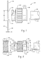
- FIG. 1 is an elevation view of an embodiment of the conduit connector, not to scale
- FIG. 2 is an elevation view of components of an embodiment of the conduit connector, not to scale, showing a compression nut separated from a body for clarity;
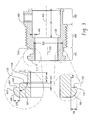
- FIG. 3 is a cross-sectional view of components of an embodiment of the conduit connector, not to scale, with exploded views of both a leading tab and a follower tab;
- FIG. 4 is a cross-sectional view of components of an embodiment of the conduit connector, not to scale, with exploded views of both a leading tab and a follower tab;
- FIG. 5 is a cross-sectional view of components of an embodiment of the conduit connector, not to scale;
- FIG. 6 is a cross-sectional view of components of an embodiment of the conduit connector, not to scale, illustrating a conduit compression system
- FIG. 7 is an elevation view of components of an embodiment of the conduit connector, not to scale, illustrating a first step in the insertion of a body into a junction box;
- FIG. 8 is an elevation view of components of an embodiment of the conduit connector, not to scale, illustrating a further step in the insertion of a body into a junction box;
- FIG. 9 is an elevation view of components of an embodiment of the conduit connector, not to scale, illustrating yet a further step in the insertion of a body into a junction box;
- FIG. 10 is an elevation view of components of an embodiment of the conduit connector, not to scale, illustrating even yet a further step in the insertion of a body into a junction box;
- FIG. 11 is an elevation view of components of an embodiment of the conduit connector, not to scale, illustrating a final step in the insertion of a body into a junction box;
- FIG. 12 is an elevation view of components of an embodiment of the conduit connector, not to scale
- FIG. 13 is a cross-sectional view of components of an embodiment of the conduit connector with a removable conduit engagement region, not to scale;
- FIG. 14 is an elevation view of components of an embodiment of the conduit connector with a removable conduit engagement region, not to scale;
- FIG. 15 is an elevation view of components of an embodiment of the conduit connector, not to scale
- FIG. 16 is a cross-sectional view of components of an embodiment of the conduit connector, not to scale;
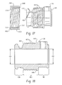
- FIG. 17 is an elevation view of components of an embodiment of the conduit connector with left-handed threads, not to scale;
- FIG. 18 is a cross-sectional view of components of an embodiment of the conduit connector, not to scale;
- FIG. 19 is an elevation view of components of an embodiment of the conduit connector with a spring separate from the body for clarity, not to scale;
- FIG. 20 is an elevation view of components of an embodiment of the conduit connector with a spring, not to scale.
- FIG. 21 is a frontal view of an embodiment of the conduit connector, not to scale.
- FIG. 22 is a partial side view of an embodiment of the conduit connector engaging and enclosure, and comprising the spring and the engagement element.
- a conduit connector is designed to quickly, safely, and rigidly connect to a junction box to facilitate the connection of a conduit to cables (and other electrical conductors) and to a wide variety of boxes (e.g., junction boxes, and so forth). Therefore, as used in this specification, the term conduit is not limited to standard rigid electrical conduit, but shall be intended to mean any type of conduit, any type of cable, or any other type of electrical conductor.
- the junction box is intended to include many types of electrical enclosures, such as, outlet and fixture boxes, enclosures for disconnect switches and motor starters, and transformer enclosures.
- the junction box can be made from steel, plastic, or other commercially feasible and acceptable materials.
- the junction box (200) has a box interior surface (210), a box exterior surface (220), and a box thickness (225).
- the junction box (200) has a plurality of prefabricated holes or openings each of which is covered with a plate or is formed with a thin area in the junction box (200) commonly called a knockout (230).
- the knockout (230) To insert a connector to the junction box (200), the knockout (230) must be exposed by knocking out the cover piece or perforating the thin area.
- some junction boxes (200) do not have removable covers or thin areas that can be prepped to receive a connector. In this situation, knockouts (230) are cut in the desired location with a punch and die set.
- the knockout (230) has a knockout diameter or an opening (232) and a knockout edge (234).
- the conduit (300) can be rigid or flexible conduit, or any type of hollow tubing commonly used in electrical installations.
- the conduit (300) can be made from metal (e.g., zinc, steel, aluminum, iron, and so forth), plastic (e.g., polycarbonate, polyamide) or other commercially feasible and acceptable material, or a combination comprising at least one of the foregoing.
- the conduit (300) has a conduit interior surface (310), a conduit exterior surface (320), a conduit thickness (340), and a conduit leading edge (330), as seen generally in FIGS. 1 and 2 .
- the two primary components will be briefly described so the operation of the connector (100) can be explained.
- the conduit connector (100) includes a body (400) and a compression nut (1000).
- the body (400) has a distal end (410), a proximal end (420), a body interior surface (430), and a body exterior surface (450).
- the body interior surface (430) defines an inlet diameter (432) and an outlet diameter (434).
- the outlet diameter (434) is coaxial with the inlet diameter (432).
- a central axis (436) intersects the outlet and inlet diameters (434,432) midpoints.
- a conduit stop (438) projects from the body interior surface (430) a conduit stop projection distance (440).
- the conduit stop (438) limits the distance that the conduit leading edge (330) can extend into the body (400).
- the body (400) can be formed a variety of materials including, but not limited to, metal (e.g., zinc, steel, aluminum, iron, and so forth), plastic (e.g., polycarbonate, polyamide), or a combination comprising at least one of the foregoing, e.g., a plastic comprising metal fibers and/or particles.
- the body (400) can be formed employing various techniques such as cast, pressed, machined from stock, injection molded, or manufactured by other processes utilized for manufacturing electrical connectors.
- the body (400) can have three regions: namely, a box engagement region (500), an optional nut engagement region (800), and a conduit engagement region (900).
- the box engagement region (500) is positioned at the distal end (410) of the body (400) and cooperates with the knockout (230) to attach the body (400) to the junction box (200).
- the box engagement region (500) has a leading edge (510), a secondary edge (520), a root surface (530), a leading tab (600) and a follower tab (700).
- the leading tab (600) and the follower tab (700) are located between the leading edge (510) and the secondary edge (520) and extend radially outward.
- the leading tab (600), the root surface (530), and the follower tab (700) will be described more below.
- the leading tab (600) has a leading tab perimeter edge (610), a leading tab primary contact surface (620), a leading tab centering ledge (640), and a leading tab centering flank (650), as seen in FIG. 3 .
- the leading tab (700) extends radially a leading tab height (630) from leading edge (510).
- the leading tab centering flank (650) extends from the root surface (530) to the leading tab centering ledge (640).
- a flank angle (652) exists between the leading tab centering flank (650) and the leading tab centering ledge (640).
- the leading tab centering ledge (640) has a ledge width (642) which is the maximum width of the leading tab centering ledge (640) as measured from the intersection of the leading tab centering ledge (640) with the leading tab centering flank (650) and the intersection of the leading tab centering ledge (640) and the leading tab primary contact surface (620).
- the flank angle (652) can be approximately ninety-one degrees to approximately one hundred and seventy-nine degrees (specifically, about one hundred degrees to about one hundred fifty degrees, and more specifically, about one hundred twenty degrees to about one hundred forty degrees).
- leading tab centering ledge (640), the leading tab centering flank (650) oriented at the flank angle (652) imparts a desired self-centering feature of the body (400) in the knockout (230) and eases assembly.
- the distance from leading tab primary contact surface (620) to the body distal end (410) is greater than 150% of the box thickness (225), and the ledge width (642) is substantially equal to or less than the box thickness (225). This relationship provides a minimum protrusion into the interior of the box (200) while simultaneously enhancing the structural strength of the tabs (600,700) and the centering of the body (400) in the knockout (230).
- the leading tab centering ledge (638) can form a projection or lug (see FIG. 22 ).
- the lug can project from the leading tab primary contact surface (620) toward the secondary edge (520) such that, when the connector is connected to an enclosure (e.g., through a hole in a wall of the enclosure), the leading tab primary contact surface (620) contacts the box interior surface (210), while the leading tab centering ledge (638) exerts lateral pressure on the wall of the knockout edge (234).
- the leading tab centering ledge (638) can have a sufficient length to protrude out of the knockout (230) toward the body (400) (e.g., the lug can have a length that is greater than or equal to the thickness of the wall (234) from interior surface (210) to the exterior surface (220)).
- the engagement element (638) can have an upper portion (634) that extends substantially perpendicularly from the leading tab primary contact surface (620). This upper portion (634) can physically contact and, desirably, can exert lateral pressure on the knock out edge (234) to further retain the connector in the knockout.
- the engagement element (638) can also have various geometries that enable the desired engagement with the knockout edge, such as polygonal (e.g., square, rectangular, triangular, and so forth), and/or a rounded geometry. Illustrated in FIG. 22 is a generally triangular geometry with a rounded edge.
- the engagement element e.g., lug
- other engagement element(s) can be employed to enhance the retention of the connector in the enclosure and inhibit unintentional removal; e.g., to inhibit accidental dislodging of the connector due to bumping, vibrations, and so forth.
- the root surface (530) defines a root surface diameter (532) having a root surface central axis (533) that is offset from the central axis (436), as seen in FIG. 3 .
- the root surface (530) a minimum root surface width (534) which is defined as a distance from the box engagement region secondary edge (520) to the nearest intersection of the root surface (530) and the leading tab centering flank (650). The functioning of the root surface (530) during assembly will be described in greater detail below.
- the follower tab (700) also has a perimeter edge (710) and a primary contact surface (720).
- the leading tab (700) extends radially a leading tab height (730) from the box engagement region leading edge (510).
- the leading tab perimeter edge (610) and the follower tab perimeter edge (710) form a tab perimeter diameter (760), as shown in FIG. 2 .
- the tab perimeter diameter (760) is larger than the knockout diameter (232) to permit the body (400) to be secured to the junction box (200).
- the follower tab (700) has a follower tab centering ledge (740) and a follower tab centering flank (750) which extends from the root surface (530) to the follower tab centering ledge (740), as seen in FIGS.
- a follower tab flank angle (752) exists between the follower tab centering flank (750) and the follower tab centering ledge (740).
- the follower tab centering ledge (740) has a follower tab ledge width (742) which is the maximum width of the follower tab centering ledge (740) as measured from the intersection of the follower tab centering ledge (740) with the follower tab centering flank (750) and the intersection of the follower tab centering ledge (740) and the follower tab primary contact surface (720).
- the follower tab flank angle (752) can be approximately ninety-one degrees to approximately one hundred and seventy-nine degrees (specifically, about one hundred degrees to about one hundred fifty degrees, and more specifically, about one hundred twenty degrees to about one hundred forty degrees).
- the leading and follower tab primary contact surfaces (620,720) have grip enhancing features (622,722).
- the grip enhancing features (622,722) reduce the relative motion between the leading and follower tab primary contact surfaces (620,720) and the box interior surface (210).
- the grip enhancing features (620,720) can be adhesive, a pressure sensitive adhesive that is activated by removal of a releasable covering, or a rubber-like gasket or o-ring.
- the grip enhancing features (622,722) are gripping projections (623,723), as seen in the exploded views in FIG. 4 .
- the grip projections can be knurling, checkering, knobs, teeth, texturing of the surface, a plurality of surface features, as well as combinations comprising at least one of the foregoing, that come into contact with the box interior surface (210) and increase the frictional forces between the leading and follower tabs (600,700) and the box interior surface (210) substantially preventing rotation of the body (400).
- the body (400) has two radially extending tabs, that is, the leading tab (600) and the follower tab (700).
- leading tab (600) may operate with the root surface (530), or multiple leading tabs (600) in combination with a plurality of follower tabs (700) in operation with the root surface (530) where the tabs (600,700) are positioned in a generally opposing manner will also provide the inventive assembly system.
- FIG. 5 shows the nut engagement region (800), which has a nut engagement region proximal end (810), a nut engagement region distal end (820), and a plurality of nut engagement region threads (830).
- the nut engagement region (800) cooperates with the compression nut (1000).
- the nut engagement region (800) is formed with a nut stop (840).
- the nut stop (840) is positioned at the nut engagement region proximal end (810) adjacent to the conduit engagement region (900).
- the nut stop (840) facilitates the assembly of the connector (100) at the factory and removal of the connector (100) from the junction box (200) by preventing the compression nut (1000) from being rotated off the body proximal end (420).
- the conduit engagement region (900) has a conduit compression system (920) for frictionally securing the conduit (300) within the body (400), as seen in FIG. 6 .
- the conduit compression system (920) is a setscrew (922) and a setscrew receiver (924).
- the setscrew receiver (924) is formed in the conduit engagement region (900) and extends from the body interior surface (430) to the body exterior surface (450). The setscrew (922) is threaded through the setscrew receiver (924).
- a conduit inlet chamfer (910) can be formed in the conduit engagement region (900) to ease initial insertion of the conduit (300) into the body proximal end (420).
- the body exterior surface (450) at the conduit engagement region (900) defines a body exterior surface inlet diameter (452), as seen in FIG. 2 , and the root surface diameter (532) is less than the body exterior surface inlet diameter (452).
- FIGS. 12 - 14 illustrate an embodiment where the conduit engagement region is a removable conduit engagement region (930).
- the removable conduit engagement region (930) has a threaded connector (932) for cooperating with the body interior surface (430) having a plurality of internal body threads (448).
- Figure 14 illustrates the removable conduit engagement region (930) threaded into the body (400).
- the removable engagement region (930) can be a commercially available electrical connector without the locknut.
- the body (400) can be formed with the internal body threads (448) that are sized to cooperate with the male threaded end of a typical electrical connector.
- the conduit connector (100) can have an optional compression nut (1000) and associated features.
- the compression nut (1000) which is shown separate from the body (400), has an exterior surface (1020) and a nut interior surface (1010) having a plurality of nut threads (1012) that cooperate with the nut engagement region threads (830).
- the nut exterior surface (1020) can be formed with texturing to facilitate operation manually or formed with features for cooperating with tools.
- the compression nut (1000) has a nut free edge (1040) that can physically contact the nut stop (840).
- the nut stop (840) as shown in FIG.
- the compression nut (1000) prevents the compression nut (1000) from being rotated off the nut engagement region proximal end (810) during assembly following manufacturing or during disassembly of the connector (100) from an electrical installation, thus preventing loss of the compression nut (1000). It is appreciated that the location of the compression nut (1000) on the body (400) is for utilizing the application in electrical installations. In this design, the user does not need to remove the compression nut (1000) prior to installation. Additionally, the compression nut (1000) is easily maneuvered against the box exterior surface (220) without the user placing their hand inside the junction box (200). The compression nut (1000) also has a nut contact edge (1030) having a nut contact surface (1032) for engaging the box exterior surface (220).
- the compression nut contact surface (1032) has a grip enhancing feature (1034) to reduce the relative motion between the compression nut (1000) and the box exterior surface (220) while in contact with one another.
- the grip enhancing feature can be adhesive, a pressure sensitive adhesive that is activated by removal of a releasable covering, or a rubber-like gasket or o-ring.
- the grip enhancing feature (1034) is a gripping projection (1035), as shown in FIG. 4 .
- the gripping projection (1035) can comprise knurling, knob(s), checkering, teeth, texturing of the surface, or a plurality of surface features that come into contact with the box exterior surface (220), and any combination comprising at least one of the foregoing.
- the gripping projection (1035) increases the frictional forces between compression nut (1000) and the box exterior surface (220) substantially preventing unintentional rotation of the compression nut (1000).
- the orientation of the various elements of the connector (100) imparts the desired functionality of the connector (100).
- the installation of the connector (100) is illustrated in FIGS. 7 - 11 .
- FIG. 7 illustrates that once the knockout (230) is exposed or created, the leading tab (600) can be inserted from the outside of the junction box (200) into the knockout (230) by angling the body (400) such that the central axis (436) is not orthogonal to the knockout (230). Once the leading tab (600) is on the inside of the junction box (200), the knockout edge (234) is brought into contact with the root surface (530), as shown in FIG. 8 .
- the central axis (436) is then reoriented orthogonally to the knockout (230) while holding the knockout edge (234) in contact with the root surface (530), as shown in FIG. 9 .
- the root surface central axis (533) is offset from the central axis (436) toward the follower tab (700) by a sufficient amount (e.g., greater than or equal to 8%) to accommodate a larger variation in standard knockout diameters thereby providing for easier installation.
- the follower tab (700) passes through the knockout (230) into the junction box (200). At this point, both the leading and follower tabs (600,700) are on the inside of the junction box (200).
- the body (400) is drawn tight to the junction box (200), as seen in FIG. 10 , by rotating the compression nut (1000) so the nut contact edge (1030) presses against the box exterior surface (220). By continuing to rotate the compression nut (1000), the nut contact edge (1030) forces the knockout edge (234) onto the leading tab centering flank (650). Further rotation of the compression nut (1000) pushes the knockout edge (234) onto the leading tab centering ledge (640), substantially centering the body (400) in the knockout (230), as seen in FIG. 11 .
- the leading tab and follower tab primary contact surfaces (620,720) engage the box interior surface (210). Additional rotation of the compression nut (1000) compresses the junction box (200) between the compression nut contact surface (1032) and the leading and follower tab primary contact surfaces (620,720). Actual tightening can be accomplished by manual manipulation or by application of tools to the nut exterior surface (1020). In an embodiment, as seen in FIG.
- the compression nut (1000) is rotated in the counter-clockwise direction to tighten the compression nut (1000) against the junction box exterior surface (220), that is, the nut threads (1012) advance to the left, commonly referred to as left-handed threads.
- the left-handed threaded design of the nut engagement region threads (830) and the compression nut threads (1012) is useful for maintaining a tight connection to junction boxes installed on equipment which have clockwise rotational motion.
- a locknut required a great degree of tactility to hold and to thread onto the male threaded connector, the difficulty of which is accentuated and prolonged when wearing gloves. So, even in frigid temperatures, to reduce the installation time, electricians generally do not wear gloves to protect their hands.
- the body (400) can be easily removed from the junction box (200) and then later reused. Most importantly, however, the compression nut (1000) remains attached to the body (400). In other words, there is no need to remove the compression nut (1000) to disconnect the body (400) from the junction box (200).
- the body (400) and the compression nut (1000) remain an integral unit through any number of connections and disconnections.
- the connector (100) may also be easily installed while wearing gloves because the removable locknut is absent. Additionally, the connector (100) does not require access to the interior of the junction box (200) to rigidly connect the conduit (300). All connections between the conduit and the junction box (200) can proceed without opening or removing the cover of the junction box (200).
- a spring (1100) can be employed.
- the spring e.g., a leaf spring
- the spring is configured to engage the conduit (300) and the junction box (not shown), e.g., the secondary edge (520) of the connector 100 and the outer surface of the junction box, to compress the leading and following tabs against an inner surface of the junction box.
- the spring comprises a general geometry enabling it to mate with the connector (100) (while the leading and following tabs (600, 700) engage an interior wall of a junction box) and the junction box.
- the geometry can be generally "U” shaped with a convex/concave mid-portion (1108) such that the spring curves outward from both the top end (1110) and the bottom end (1112) toward the mid-portion (1108); it is bowed (e.g., arched).
- the spring further comprises a top end (1110) and a bottom end (1112).
- the spring can comprise a notch (1102) located at the top end (1110) configured to engage with a projection (1104) on the body (400) at the secondary edge (520), e.g., to facilitate proper alignment of the spring, facilitate installation of the spring, and/or to enhance retention of the spring as desired.
- the spring (1100) further comprises angled lip(s) (1116) located at the bottom end (1112) configured to engage the secondary edge (520).
- FIG. 20 illustrates a completed assembly of the conduit connector (100) and the spring (1100).
- the mating of the notch (1102) located at the top end (1110) of the spring (1100) and the projection (1104) located on the body (400) aids in stabilizing and securing the spring (1100) on the box engagement region (500) prior to connection to the junction box (200).
- the projection can protrude from the body (400) at any appropriate angle to attain the desired securing and stabilizing.
- the projection (1104) can form a substantially 90° angle with the secondary edge (520), or the projection (1124; (see Figure 22 )) can form a less than 90° angle with the secondary edge (520), projecting down toward the root surface (530) (e.g., forming an angle of 35° to 75°).
- the spring (1100) may comprise a resilient material such as metals (e.g., zinc, steel, aluminum, iron, bronze, beryllium, copper and so forth), plastic and/or any other material with a spring/memory quality, or a combination comprising at least one of the foregoing, such as spring steel.
- the spring (1100) is placed on the box engagement region (500) of the conduit (300) and engages both the connector (100) and the opening (232) in the junction box (200).
- the connector (100) can be angled toward the opening (232) in the junction box (200) such that the spring (1100) is engaged with the opening (232) in the junction box (200) by straightening the connector (100) in a downward direction while simultaneously pushing the box engagement region (500) in a forward and upward direction.
- the spring (1100) does not enter the opening (232) in the junction box (200), but rather remains on the outside of the opening before and after installation.
- the spring (1100) secures the connector (100) to the opening (232) in the junction box (200) and prevents the connector (100) from releasing from the opening (232) after the connector (100) has been straightened.
- the use of this spring renders the use of a compression nut optional, since the spring (1100) forms the desired compressive force, retaining the connector in place.
- the distal end (410) of the connector (100) contains a throat section (1114).
- the throat section (1114) can be a rectangular shape, but any other commercially feasible and acceptable shape can also be used.
- the body (400) of the conduit (300) contains a smooth transition from the rounded or other shape at the proximal end (420) of the body (400) to the throat section (1114) to assist the wires passing through and to prevent chafing or cutting of the wires.
- the connector (100) can further contain a gasket or sealing ring when a liquid tight seal is desired.
- the connector (100) can have a smooth, rounded surface for the gasket or sealing ring to attach.
- the connector (100) can be made in any configuration, including, straight, 45 degree, 90 degree, or any other degree.
- the conduit (300) is attached to the body (400).
- the conduit (300) is attached to the body (400) by inserting the conduit leading edge (330) to the conduit stop (438).
- the conduit compression system (920) fractionally secures the conduit (300) to the body (400).
- a plurality of electrical wires or cables is passed through the conduit (300), through the body interior surface (430), and into the junction box (200).
- the conduit (300) can be inserted through the body (400) into the junction box (200), or at least inserted through the body (400) to an adequate depth to assure a firm grip by the conduit engagement region (900) on the conduit (300) or cable.
- This embodiment can be suitable for passing flexible cable, portable cord and the like into the junction box (200).
- the conduit connector can be used in a variety of fashions including, connectors for metallic conduits, non metallic flexible conduits, armored cables, metal clad (MC) cables, non-metallic sheathed cables, flexible metal conduits, cord grip/strain relief/cable gland connectors, etc.
- This conduit connector (100) succeeds in reducing cost by saving time and labor during both manufacturing and installation.
- the connector (100) also occupies minimal space inside the connector, reducing or eliminating interference problems that may occur with standard locknut connectors (e.g., when the installer must to shorten the device mounting screws).
- the conduit connector (100) further increases safety, as no fingers or tools touch the inside of the connector (100), where hot, energized areas are located.
- conduit connector (100) has been described in relation to conduit connector (100), it can be employed with various conduit connectors which can optionally comprise the projection (1104). These conduit connectors will have a region for receiving the spring, and enabling the spring to form a pressure fit between the box and the conduit connector, when in use.
- the conduit connector (100) can comprise: a body (400) comprising a box engagement region (500) capable of engaging an opening (232) in a junction box (200) and a spring (1100) configured to engage the connector (100) and the junction box (200).
- the box engagement region (500) can have a root surface (530), a leading tab (600), and a follower tab (700) wherein the root surface (530) and leading tab (600) can be located between a leading edge (510) and a secondary edge (520).
- a leading tab perimeter edge (610) and a follower tab perimeter edge (710) define a tab perimeter diameter (760) that is larger than an opening (232) in the junction box (200).
- a method for connecting a connector (100) to a junction box (200) comprises: angling the connector (100) toward the opening in the junction box (200), inserting the leading tab (600) into the opening (232); inserting the follower tab (700) into the opening (232); straightening the connector (100) in a downward direction while pushing the box engagement region (500) in a forward and upward direction; and placing a spring (1100) onto a body (400) of the connector (100), wherein the spring (1100) engages the body (400) and a junction box (200).
- the connector (100) can comprise the body (400) comprising a box engagement region (500) capable of engaging an opening (232) in the junction box (200).
- the box engagement region (500) can have a root surface (530), a leading tab (600), and a follower tab (700), wherein the leading tab has a leading tab perimeter edge (610) the follower tab (700) has a follower tab perimeter edge (710).
- the leading tab perimeter edge (610) and the follower tab perimeter edge (710) can define a tab perimeter diameter (760) that is larger than the opening (232) in the junction box (200).
- the spring can: (i) be a leaf spring; (ii) comprise a notch (1102) located on a top end (1110) of the spring (1100) configured to engage a projection (1104) located on the body (400) at the secondary edge (520), projecting toward the leading tab (600); (iii) comprise a notch (1102) configured to engage a projection (1104) on the body (400) at the second edge (520); and/or (iv) comprise an angled lip (1116) located at a bottom end (1112), wherein the angle lip (1116) and the top end (1110) are configured to contact the secondary edge (520), while a mid-portion (1108) is configured to contact the junction box (200).
- the leading tab (600) can have a leading tab perimeter edge (610), a leading tab primary contact surface (620), a leading tab centering ledge (640), and a leading tab centering flank (650) extending from the root surface (530) to the leading tab centering ledge (640) at a flank angle (652), measured from the leading tab centering ledge (640) to the leading tab centering flank (650), that is between approximately ninety-one degrees and approximately one hundred and seventy-nine degrees.
- the leading tab can have engagement element configured to engage the enclosure, e.g., to inhibit unintentional removal of the connector from the enclosure.
- the engagement element can be a leading tab centering ledge configured to extend, when the connector is connected to the enclosure, from the leading tab primary contact surface through the opening such that the leading tab centering ledge exerts lateral pressure on the opening.
- the body (400) can further comprise a nut engagement region (800) and a conduit engagement region cooperating with the conduit (300).
- the root surface (530) can defines a root surface diameter (532) that is not coaxial with a body inlet diameter (432) or a body outlet diameter (434).
- the various embodiments can further comprise a conduit stop (438) projecting from the body (400) a conduit stop projection distance (440) thereby limiting the distance a conduit leading edge (330) can extend into the body (400).
- the root surface diameter (532) can have a root surface central axis (533) offset from a central axis (436) by at least 8% of the tab perimeter diameter (760), wherein the offset can optionally be toward the follower tab (700).
- the junction box (200) can further comprise a box thickness (225), wherein the distance from a leading tab primary contact surface (620) to a body distal end (410) is greater than 150% of the box thickness (225) and the leading tab centering ledge (640) has a ledge width (642) which is substantially equal to or less than the box thickness (225).
- the root surface (530) can have a minimum root surface width (534) which is the smallest distance between the box engagement region secondary edge (520) and an intersection between the leading tab centering flank (650) and the root surface (530) and where the minimum root surface width (534) is at least 150% of the box thickness (225).
- the follower tab (700) can have a follower tab centering ledge (740) and a follower tab centering flank (750) extending from the root surface (530) to the follower tab centering ledge (740) at a flank angle (752), measured from the follower tab centering ledge (740) to the follower tab centering flank (750), and wherein the body (400) is configured to be drawn tight to the junction box (200) by the spring (1100) such that the follower tab centering flank (750) directs a knockout edge (234) onto the follower tab centering ledge (740) thereby substantially centering a central axis (436) in the knockout (230) and pinching the junction box (200) between the spring (1100) and the leading tab (600) and the follower tab (700) thus releasably securing the body (400) to the junction box (200).
- the conduit connector answers a long felt need for an electrical connector which can be installed quickly and easily without tools, does not require access to the interior of a junction box, and does not need to be disassembled before connecting it to an electrical enclosure.
- the electrical connector has utility, among other uses, in connection of conduit to junction boxes.
- the present application discloses an electrical connector having a body and optionally a compression nut.
- the body can have a box engagement region, a nut engagement region, a spring, and/or a conduit engagement region.
- the box engagement region facilitates connection with the junction box.
- the nut engagement region and or spring can cooperate with the compression nut to rigidly fix the body to the junction box.
- the conduit engagement region can cooperate with a variety of conduit, cables, and other electrical conductors.
Landscapes
- Engineering & Computer Science (AREA)
- Architecture (AREA)
- Civil Engineering (AREA)
- Structural Engineering (AREA)
- Connection Or Junction Boxes (AREA)
- Quick-Acting Or Multi-Walled Pipe Joints (AREA)
Applications Claiming Priority (2)
| Application Number | Priority Date | Filing Date | Title |
|---|---|---|---|
| US6755308P | 2008-02-29 | 2008-02-29 | |
| US6915608P | 2008-03-13 | 2008-03-13 |
Publications (2)
| Publication Number | Publication Date |
|---|---|
| EP2096728A2 true EP2096728A2 (fr) | 2009-09-02 |
| EP2096728A3 EP2096728A3 (fr) | 2011-08-03 |
Family
ID=40666941
Family Applications (1)
| Application Number | Title | Priority Date | Filing Date |
|---|---|---|---|
| EP09153657A Withdrawn EP2096728A3 (fr) | 2008-02-29 | 2009-02-25 | Connecteur de conduit |
Country Status (3)
| Country | Link |
|---|---|
| US (1) | US8129634B2 (fr) |
| EP (1) | EP2096728A3 (fr) |
| CA (1) | CA2655386A1 (fr) |
Cited By (2)
| Publication number | Priority date | Publication date | Assignee | Title |
|---|---|---|---|---|
| WO2016177864A1 (fr) * | 2015-05-06 | 2016-11-10 | Eaton Protection Systems Ip Gmbh & Co. Kg | Passage de câble/ligne |
| WO2025017446A1 (fr) * | 2023-07-14 | 2025-01-23 | Eaton Intelligent Power Limited | Ensemble presse-étoupe à fixation et retrait rapides |
Families Citing this family (26)
| Publication number | Priority date | Publication date | Assignee | Title |
|---|---|---|---|---|
| US8901441B2 (en) * | 2008-10-08 | 2014-12-02 | Sigma Electric Manufacturing Corporation | Conduit connector and methods for making and using the same |
| JP5279696B2 (ja) * | 2009-12-24 | 2013-09-04 | 株式会社ハイレックスコーポレーション | 端末支持装置 |
| US8857039B2 (en) | 2010-02-19 | 2014-10-14 | Sigma Electric Manufacturing Corporation | Electrical box conduit connectors and methods for making and using the same |
| US8803008B2 (en) | 2011-03-03 | 2014-08-12 | Sigma Electric Manufacturing Corporation | Conduit connector and methods for making and using the same |
| USD666153S1 (en) * | 2011-07-18 | 2012-08-28 | Bridgeport Fittings, Inc. | Flexible metal conduit connector with external bonding connector |
| CA2788787C (fr) | 2011-09-01 | 2019-06-04 | Sigma Electric Manufacturing Corporation | Connecteur de conduite et ses methodes de fabrication et d'utilisation |
| US10014673B2 (en) | 2013-11-19 | 2018-07-03 | Fortune Industries International, Inc. | Quick lock system for joining and aligning tubes, conduits and junction boxes |
| US9762041B1 (en) | 2013-11-19 | 2017-09-12 | Fortune Industries International, Inc. | Quick lock system for joining and aligning tubes, conduits and junction boxes |
| US10594120B2 (en) | 2013-11-19 | 2020-03-17 | Fortune Industries International, Inc. | Quick lock system for joining and aligning tubes, conduits and junction boxes |
| US10763654B2 (en) | 2013-11-19 | 2020-09-01 | Fortune Industries International, Inc. | Quick lock system for joining and aligning tubes, conduits and junction boxes |
| CA2928093A1 (fr) * | 2013-11-19 | 2015-05-28 | David Hong Yeh | Systeme de fixation de tube a verrouillage rapide |
| US10483734B2 (en) | 2013-11-19 | 2019-11-19 | Fortune Industries International, Inc. | Quick lock system for joining and aligning tubes, conduits and junction boxes |
| USD777565S1 (en) | 2014-02-12 | 2017-01-31 | David Hong Yeh | Connector |
| USD754303S1 (en) * | 2014-07-03 | 2016-04-19 | Bridgeport Fittings, Inc. | Side load conduit connector |
| EP2998166B1 (fr) * | 2014-09-16 | 2017-08-30 | Delphi Technologies, Inc. | Système de fixation utilisable pour des connecteurs |
| US9472933B2 (en) | 2014-10-14 | 2016-10-18 | Saeed Nikayin | Conduit locking connector |
| US9373919B1 (en) | 2015-07-20 | 2016-06-21 | Bridgeport Fittings, Inc. | Adjustable metal-clad cable/flexible metallic conduit electrical connector |
| USD788043S1 (en) | 2015-07-20 | 2017-05-30 | Bridgeport Fittings, Inc. | Adjustable electrical connector |
| DE102017209368A1 (de) * | 2017-01-25 | 2018-07-26 | Icotek Project Gmbh & Co. Kg | Kabeldurchführung mit abschirmenden und abdichtenden Eigenschaften |
| US10892610B2 (en) * | 2019-05-30 | 2021-01-12 | Bridgeport Fittings, Llc | Adjustable transition coupler |
| US11143343B2 (en) * | 2019-05-30 | 2021-10-12 | Bridgeport Fittings, Llc | Adjustable transition coupler |
| USD940081S1 (en) | 2019-10-04 | 2022-01-04 | Arlington Industries, Inc. | Flanged conduit cap with coupling |
| US10958051B1 (en) | 2020-01-28 | 2021-03-23 | Anthony James Howard | Electrical conduit connector |
| GB202010771D0 (en) * | 2020-07-13 | 2020-08-26 | Niglon Ltd | Electrical conduit junction boxes |
| US11682886B1 (en) | 2022-07-12 | 2023-06-20 | Genwire LLC | Foldable electrical cable clamp |
| US12553548B2 (en) | 2023-11-01 | 2026-02-17 | Coupler Solutions, Llc | Conduit coupler and methods of use thereof |
Family Cites Families (33)
| Publication number | Priority date | Publication date | Assignee | Title |
|---|---|---|---|---|
| US1131399A (en) * | 1911-06-23 | 1915-03-09 | Handy Mfg Company | Outlet-box. |
| US1049283A (en) * | 1912-11-15 | 1912-12-31 | Carl Westphal | Pipe-joint. |
| US1355450A (en) * | 1917-02-17 | 1920-10-12 | Elmer Conrad Carlson | Coupling |
| US1659094A (en) * | 1925-10-21 | 1928-02-14 | Fred A Godfrey | Conduit attaching to outlet boxes |
| US2365785A (en) * | 1942-04-16 | 1944-12-26 | Tinnerman Products Inc | Fastening device |
| US4151363A (en) * | 1976-12-20 | 1979-04-24 | Nichols Wayne L | Method and apparatus for joining electrical conductors to junction boxes |
| US4496791A (en) * | 1982-10-13 | 1985-01-29 | Allen-Bradley Company | Spring-biased connector for electrically bonding a device to a supporting wall |
| US4641863A (en) * | 1985-11-12 | 1987-02-10 | Sami Shemtov | Connector for coupling a conduit to a junction box |
| US4990721A (en) * | 1990-01-12 | 1991-02-05 | Corecon Corporation | Armored cable connector |
| US5132493A (en) * | 1991-01-25 | 1992-07-21 | Sheehan Robert K | Device for connecting non-metallic sheathed cable to an electric box |
| US5200575A (en) * | 1991-01-25 | 1993-04-06 | Sheehan Robert K | Connector assembly for conduit |
| US5422437A (en) * | 1993-04-16 | 1995-06-06 | Hubbell Incorporated | Electrical connector assembly |
| US5866853A (en) * | 1993-10-07 | 1999-02-02 | Sheehan; Robert K. | Liquid-tight, strain-relief connector for connecting conduit and the like |
| US5894109A (en) * | 1996-09-13 | 1999-04-13 | Thomas & Betts Corporation | Locknutless conduit connector |
| US5775739A (en) * | 1997-01-10 | 1998-07-07 | Arlington Industries, Inc. | Electrical connector |
| US5789706A (en) * | 1997-01-17 | 1998-08-04 | Perkins; Vernon | Electrical cable to utilization device quick connector |
| US6604400B1 (en) * | 1998-01-15 | 2003-08-12 | Arlington Industries, Inc. | Electrical connector |
| US6335488B1 (en) * | 1998-10-02 | 2002-01-01 | Arlington Industries, Inc. | Snap in cable connector |
| US6849803B1 (en) * | 1998-01-15 | 2005-02-01 | Arlington Industries, Inc. | Electrical connector |
| US6709280B1 (en) * | 2002-01-17 | 2004-03-23 | Arlington Industries, Inc. | Fitting with improved continuity |
| US6020557A (en) * | 1998-02-05 | 2000-02-01 | Hubbell Incorporated | Conduit connector assembly with angled conduit gripping means |
| US6034326A (en) * | 1998-02-05 | 2000-03-07 | Hubbell Incorporated | Conduit connector assembly spring clip having scalloped shaped conduit gripping end |
| US6262369B1 (en) * | 1998-09-29 | 2001-07-17 | Thomas & Betts International, Inc. | Conduit connector providing dual diameter end stops |
| US6133529A (en) * | 1999-12-29 | 2000-10-17 | Arunction Industries, Inc. | Liner assembly |
| US6352439B1 (en) * | 2000-05-05 | 2002-03-05 | Arlington Industries, Inc. | Threaded snap in connector |
| US6872886B2 (en) * | 2001-05-01 | 2005-03-29 | Bridgeport Fittings, Inc. | Electrical cable connector |
| US6737584B2 (en) * | 2001-05-01 | 2004-05-18 | Bridgeport Fittings, Inc. | Electrical cable connector |
| US6642451B1 (en) * | 2001-10-22 | 2003-11-04 | Arlington Industries, Inc. | Electrical connector |
| US6596939B1 (en) * | 2001-12-26 | 2003-07-22 | Arlington Industries, Inc. | Threaded snap in connector |
| US6916988B1 (en) * | 2004-07-12 | 2005-07-12 | Bridgeport Fittings, Inc. | Electrical connector with frustro conical snap fit retaining ring |
| US7338092B1 (en) * | 2005-07-25 | 2008-03-04 | Cicconi Iii David Lee | Quick-release connector fitting |
| US7078623B1 (en) * | 2005-11-30 | 2006-07-18 | Sheehan Robert K | Electrical conduit to junction box connection system |
| US7220923B1 (en) * | 2006-06-30 | 2007-05-22 | Internatioinal Metal Hose Company | Clip-on electrical conduit connector |
-
2009
- 2009-02-24 US US12/391,868 patent/US8129634B2/en not_active Expired - Fee Related
- 2009-02-25 CA CA002655386A patent/CA2655386A1/fr not_active Abandoned
- 2009-02-25 EP EP09153657A patent/EP2096728A3/fr not_active Withdrawn
Cited By (3)
| Publication number | Priority date | Publication date | Assignee | Title |
|---|---|---|---|---|
| WO2016177864A1 (fr) * | 2015-05-06 | 2016-11-10 | Eaton Protection Systems Ip Gmbh & Co. Kg | Passage de câble/ligne |
| US10211616B2 (en) | 2015-05-06 | 2019-02-19 | Eaton Protection Systems Ip Gmbh & Co. Kg | Cable/line insertion |
| WO2025017446A1 (fr) * | 2023-07-14 | 2025-01-23 | Eaton Intelligent Power Limited | Ensemble presse-étoupe à fixation et retrait rapides |
Also Published As
| Publication number | Publication date |
|---|---|
| CA2655386A1 (fr) | 2009-08-29 |
| EP2096728A3 (fr) | 2011-08-03 |
| US8129634B2 (en) | 2012-03-06 |
| US20090218131A1 (en) | 2009-09-03 |
Similar Documents
| Publication | Publication Date | Title |
|---|---|---|
| US8129634B2 (en) | Conduit connector | |
| EP1969689B1 (fr) | Sytème de connexion de conduit électrique à une boîte de raccordement | |
| US8857039B2 (en) | Electrical box conduit connectors and methods for making and using the same | |
| US8901441B2 (en) | Conduit connector and methods for making and using the same | |
| CA2788787C (fr) | Connecteur de conduite et ses methodes de fabrication et d'utilisation | |
| USRE47893E1 (en) | Conduit connector and methods for making and using the same | |
| US5189258A (en) | Apparatus for directly attaching a strain relief connector to an electrical enclosure | |
| US5912431A (en) | Snap-in locknut adapter for connectors | |
| US6538201B1 (en) | Threaded snap in connector | |
| EP3539184B1 (fr) | Borne de connecteur et son procédé d'assemblage | |
| US5342994A (en) | Electrical connector for mounting to electrical enclosures | |
| CN100521421C (zh) | 快速组装电连接盒的设备以及方法 | |
| US9385520B1 (en) | Rain tight fitting for PVC jacketed metal-clad electrical cable | |
| JPH077837A (ja) | ケーブルグランド | |
| US11451027B2 (en) | Press coupler for electrical conduit | |
| US9431808B1 (en) | Electrical connector | |
| US7220923B1 (en) | Clip-on electrical conduit connector | |
| CA3106632C (fr) | Connecteur de conduite electrique | |
| CA2853404C (fr) | Raccords de conduite et procedes pour fabriquer et utiliser ceux-ci | |
| CA2770855C (fr) | Raccord de conduit et procede de fabrication et d'utilisation | |
| US10658801B1 (en) | Feedthrough connector for cable through panel | |
| CA2821441C (fr) | Connecteur electrique | |
| HK1077129B (en) | Quick assembling connection box apparatus and method |
Legal Events
| Date | Code | Title | Description |
|---|---|---|---|
| PUAI | Public reference made under article 153(3) epc to a published international application that has entered the european phase |
Free format text: ORIGINAL CODE: 0009012 |
|
| AK | Designated contracting states |
Kind code of ref document: A2 Designated state(s): AT BE BG CH CY CZ DE DK EE ES FI FR GB GR HR HU IE IS IT LI LT LU LV MC MK MT NL NO PL PT RO SE SI SK TR |
|
| AX | Request for extension of the european patent |
Extension state: AL BA RS |
|
| PUAL | Search report despatched |
Free format text: ORIGINAL CODE: 0009013 |
|
| AK | Designated contracting states |
Kind code of ref document: A3 Designated state(s): AT BE BG CH CY CZ DE DK EE ES FI FR GB GR HR HU IE IS IT LI LT LU LV MC MK MT NL NO PL PT RO SE SI SK TR |
|
| AX | Request for extension of the european patent |
Extension state: AL BA RS |
|
| RIC1 | Information provided on ipc code assigned before grant |
Ipc: H02G 3/06 20060101ALI20110629BHEP Ipc: H02G 3/00 20060101AFI20110629BHEP |
|
| AKY | No designation fees paid | ||
| REG | Reference to a national code |
Ref country code: DE Ref legal event code: R108 Effective date: 20120411 |
|
| STAA | Information on the status of an ep patent application or granted ep patent |
Free format text: STATUS: THE APPLICATION IS DEEMED TO BE WITHDRAWN |
|
| 18D | Application deemed to be withdrawn |
Effective date: 20120204 |