EP2096799A1 - Réseau de communication redondant - Google Patents
Réseau de communication redondant Download PDFInfo
- Publication number
- EP2096799A1 EP2096799A1 EP09006695A EP09006695A EP2096799A1 EP 2096799 A1 EP2096799 A1 EP 2096799A1 EP 09006695 A EP09006695 A EP 09006695A EP 09006695 A EP09006695 A EP 09006695A EP 2096799 A1 EP2096799 A1 EP 2096799A1
- Authority
- EP
- European Patent Office
- Prior art keywords
- data
- main
- participant
- participants
- data transmission
- Prior art date
- Legal status (The legal status is an assumption and is not a legal conclusion. Google has not performed a legal analysis and makes no representation as to the accuracy of the status listed.)
- Granted
Links
Images

Classifications
-
- H—ELECTRICITY
- H04—ELECTRIC COMMUNICATION TECHNIQUE
- H04L—TRANSMISSION OF DIGITAL INFORMATION, e.g. TELEGRAPHIC COMMUNICATION
- H04L12/00—Data switching networks
- H04L12/28—Data switching networks characterised by path configuration, e.g. LAN [Local Area Networks] or WAN [Wide Area Networks]
- H04L12/42—Loop networks
- H04L12/437—Ring fault isolation or reconfiguration
Definitions
- the invention relates to a method for operating a redundant, annular communication network and to a communication network which makes use of this method.
- FIG. 1a The German patent application with the file number DE 10 2004 041 093 describes such a circular communication system in FIG. 1a which could represent, for example, a control and drive systems for shaftless production machines.
- Such systems use a so-called opposing double ring for communication.
- redundancy error trap
- the double ring breaks down into two line topologies. Communication between substations that are not affected by the disturbance then takes place exclusively by copying all data sent by other participants via the main station. This significantly increases the utilization of the main station and causes propagation delays between immediately adjacent secondary participants.
- the object of the invention is to ensure a data transmission in the event of an error, to relieve the main participant as best as possible and to avoid propagation delays between secondary participants as far as possible.
- the object is achieved by means of a method for operating a redundant, annular, in particular countercommunicating, communication network with at least one main participant and at least two secondary participants, which communicate with each other by means of a data transmission device, wherein the secondary participants communicate directly by means of the data transmission device and / or indirectly by means of the Main participant and the data transmission device communicate with each other by the main participant exchanges the data to be exchanged between the secondary participants between its data transmission device terminals, in particular in accordance with a transmission clock.
- the data transmission device could, for example, be realized by means of a line-bound or radio-bound data transmission, which permits bidirectional communication.
- the subscriber's data transmission device ports are the interfaces between the main subscriber and the data communication device. Since it is a ring-shaped, redundant system, each participant (secondary participant and main participant) comprises four connections for the data transmission device (2 inputs and 2 outputs each).
- the invention provides a redundant and fail-safe system, because the secondary participants can communicate directly with each other independently of the main participant, thereby relieving them. Immediately adjacent participants thus communicate with each other on the shortest path, this reduces the duration of the data. In addition, in the case of a malfunction of the data transmission device for the secondary participants still has the opportunity to communicate by means of the main participant.
- the main participant exchanges all data sent by the secondary participants in the event of an interruption of the data transmission between two secondary participants in accordance with a transmission cycle between secondary participants.
- the master station begins to transmit all data from slave stations connected to the first communications gateway port to the second communications gateway port to which other slave stations are connected and vice versa. This ensures that each secondary participant can receive the data intended for him from the data stream.
- the secondary participants communicate efficiently with one another bypassing the main station. The utilization of the main user CPU is thus kept low, and despite the error communication can be maintained.
- the main participant exclusively exchanges cross-communication data (data determined by secondary participants for secondary participants) in the event of a disturbance of the data transmission device between the secondary participants in accordance with a transmission cycle. It is no longer exchanged all the data sent by the secondary participants, which could also contain data for a main participant, but only those data that are actually intended for other secondary participants. Data, which are to be exchanged between secondary participant and main participant, are thus not made accessible to other secondary participants. The process becomes more efficient, because the data volume is significantly reduced in this case.
- the method is further refined insofar as exclusively those secondary participants who are directly affected by a fault communicate by means of the main subscriber, in that, in particular, they recognize the fault and report it to the main subscriber.
- the main station locates the data to be copied on the basis of the now known error location. Accordingly, the main station only determines those data that are from a still functional partial line to the other still functional partial line of the communication network (see FIG. 2 ) need to be replaced. Only this data will be copied.
- Data between secondary participants, which can still communicate directly with each other are excluded from the data stream. Only the secondary participant data of secondary participants affected by the disruption, which can no longer be transmitted directly between the secondary participants, therefore find their way via the main participant.
- the disturbance is communicated to the main subscriber by means of the data transmission device and the main subscriber coordinates the communication on the basis of the localized disturbance. This method increases the efficiency due to the reduced data load in the main subscriber.
- the main participant processes the data forwarded to a secondary participant in such a way that they can be distinguished from data exchanged directly between secondary participants, for example by manipulating data fields within the data telegrams on which the data transmission is based.
- Such data processing by the secondary participant is also conceivable. This is particularly advantageous because, due to the indirect data transmission via the main subscriber, a propagation delay of the data telegrams can result. The data affected by this propagation delay are now marked separately by means of the main participant, are thus identifiable and optionally editable.
- the data is advantageously subjected to additional data processing by the secondary participants and / or the main participant.
- additional data processing for example by means of extrapolation, enables targeted time-of-flight corrections or, for example, an averaging. Errors in the system due to erroneous data is thus prevented, the system becomes more stable and less maintenance-prone.
- a wired communication network based on the inventive method, this on the Ethernet technology or based on optical fiber technology and the communication is based on a fieldbus standard.
- the Ethernet technology allows easy handling of the interconnections, as these are usually based on copper lines. Ethernet is proven, less expensive and less error prone.
- Optical fiber technology is immune to electromagnetic interference and increases data security.
- the implementation of the communication network in the context of a fieldbus network provides access to automation technology. The use of real-time communication opens up further advantageous application fields, in particular in the processing of time-critical data.
- a drive system in particular for automation purposes, uses such a communication network, this comprising as the main participant an electrical control and / or drive controller and as secondary participants electrical controls and / or electrical drive controller.
- a communication network comprising as the main participant an electrical control and / or drive controller and as secondary participants electrical controls and / or electrical drive controller.
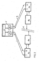
- the communication network shown comprises a main subscriber 1 with a data processing device 1c and two network connections 1a and 1b and secondary participants 2a, b, c, d, which are connected to one another by means of the bidirectional connection line 3.
- the bidirectional connection line 3 allows a direct and bidirectional data exchange between the individual secondary participants 2a, b, c, d and the main participant 1.
- bidirectional Connection line 3 in the form of an opposing ring redundancy is created by the fact that secondary participants 2a, b, c, d can communicate with each other by means of the main participant 1 by the main participant at the entrance of its terminal 1a (input / output) incoming data by means of data processing 1c on forwards the output of port 1b (input / output).
- the secondary participant 2b either the possibility to communicate directly with the secondary participant 2c by means of the bidirectional connection 3, or indirectly by means of the main participant 1.
- FIG. 2 can in the case of a line interruption 4, for example, between the secondary participants 2b and 2c, the invention be used to maintain the traffic between the secondary participants 2b and 2c on the main participant 1 upright.
- the annular communication network breaks down into a line-shaped topology, with the main participant 1 forming, together with the secondary participants 2a and 2b, a first partial line and the main participant 1 together with the secondary participants 2c and 2d forming a second partial line.
- the secondary participant 2a could now as well as the secondary participant 2b by means of the above-described data forwarding function of the main participant 1 with the secondary participant 2c and / or 2d communicate.
- the detour via the main subscriber 1 is thus selected, whereby a communication is maintained despite the error.
- the main participant 1 exchanges thus exclusively cross-communication data (user data, which are exclusively exchanged between secondary participants and no data for the main participant as such) at a line break between the secondary participants in accordance with a transmission cycle and focuses only on those required for cross-communication between the secondary participants Data, which makes the process more efficient, because the data volume is much lower in this case.
- the communication network could also be designed so that only those secondary participants 2b, 2c, which of the Line interruption 4 are directly affected, communicate by means of the main participant 1 by a secondary participant 2b, 2c detects a physical interruption 4 in the communication network and reports this interruption to the main participant 1 by means of the still functioning partial line to which it is connected.
- the secondary users 2a and 2b, and 2c and 2d would still communicate with each other directly as in the faultless case.
- the data between these sub-participants are thus excluded from the data stream that passes through the main participant 1. This reduces the amount of data to be processed by the main subscriber and additionally increases the efficiency of the network.
- main participant 1 can process data in such a way that they can be distinguished from data exchanged directly between secondary participants.
- the secondary participants 2a, b, c, d are then able, if necessary, to perform a data postprocessing in order, for example, to correct runtime errors.
- the main station 1 knows in this case the error location and is informed about which slave stations can no longer communicate directly with each other.
- the main station 1 could copy the cross-communication data from one termination 1a to the other terminal 1b and vice versa, so that both data paths, i. the direct communication between the secondary participants and the indirect communication via the main participant is available.
- the computing power available in the main subscriber 1 and the secondary subscribers 2 a, b, c, d can thus be used in an application-specific manner.
- the bidirectional connection lines 3 are preferably based on Ethernet technology (copper lines) or on optical waveguide technology.
- the use of common protocols within the current fieldbus standards provides access to the world of Automation technology, so that as the main participant 1, for example, an electrical control and as secondary participants 2a, 2b, 2c, 2d electrical controls and / or electrical drive controller may be included.
- the inventive concept increases the availability of the machines, which are realized by means of the drive system.
- the secondary participants implemented by means of control systems represent so-called substations and the main participant a so-called head station.
- controllers in ring or line form can be connected. This is also possible at the head end itself, but this preferably takes over central tasks.
- the in the FIGS. 1 and 2 The headend shown only performs higher-level, distributed control tasks, while the substations perform central control tasks.
Landscapes
- Engineering & Computer Science (AREA)
- Computer Networks & Wireless Communication (AREA)
- Signal Processing (AREA)
- Small-Scale Networks (AREA)
- Mobile Radio Communication Systems (AREA)
Applications Claiming Priority (2)
| Application Number | Priority Date | Filing Date | Title |
|---|---|---|---|
| DE102006004339A DE102006004339A1 (de) | 2006-01-30 | 2006-01-30 | Redundantes Kommunikationsnetzwerk |
| EP07001438.6A EP1814266B1 (fr) | 2006-01-30 | 2007-01-24 | Réseau de communication redondant |
Related Parent Applications (3)
| Application Number | Title | Priority Date | Filing Date |
|---|---|---|---|
| EP07001438.6A Division-Into EP1814266B1 (fr) | 2006-01-30 | 2007-01-24 | Réseau de communication redondant |
| EP07001438.6A Division EP1814266B1 (fr) | 2006-01-30 | 2007-01-24 | Réseau de communication redondant |
| EP07001438.6 Division | 2007-01-24 |
Publications (2)
| Publication Number | Publication Date |
|---|---|
| EP2096799A1 true EP2096799A1 (fr) | 2009-09-02 |
| EP2096799B1 EP2096799B1 (fr) | 2011-01-19 |
Family
ID=38006864
Family Applications (2)
| Application Number | Title | Priority Date | Filing Date |
|---|---|---|---|
| EP09006695A Not-in-force EP2096799B1 (fr) | 2006-01-30 | 2007-01-24 | Réseau de communication redondant |
| EP07001438.6A Not-in-force EP1814266B1 (fr) | 2006-01-30 | 2007-01-24 | Réseau de communication redondant |
Family Applications After (1)
| Application Number | Title | Priority Date | Filing Date |
|---|---|---|---|
| EP07001438.6A Not-in-force EP1814266B1 (fr) | 2006-01-30 | 2007-01-24 | Réseau de communication redondant |
Country Status (5)
| Country | Link |
|---|---|
| US (1) | US8559300B2 (fr) |
| EP (2) | EP2096799B1 (fr) |
| JP (1) | JP5150105B2 (fr) |
| AT (1) | ATE496456T1 (fr) |
| DE (2) | DE102006004339A1 (fr) |
Families Citing this family (10)
| Publication number | Priority date | Publication date | Assignee | Title |
|---|---|---|---|---|
| DE102004055330A1 (de) * | 2004-11-16 | 2006-05-24 | Bosch Rexroth Aktiengesellschaft | Verfahren und Vorrichtung zum Betreiben eines Netzwerkes |
| DE102005016596A1 (de) * | 2005-04-11 | 2006-10-19 | Beckhoff Automation Gmbh | Teilnehmer, Master-Einheit, Kommunikationssystem und Verfahren zu deren Betreiben |
| DE102006018884A1 (de) * | 2006-04-24 | 2007-10-25 | Beckhoff Automation Gmbh | Schnittstelleneinheit und Kommunikationssystem mit einer Master-Slave-Struktur |
| CN101132328A (zh) * | 2007-08-15 | 2008-02-27 | 北京航空航天大学 | 实时工业以太网EtherCAT通信控制器 |
| KR101720347B1 (ko) * | 2011-01-20 | 2017-03-27 | 엘에스산전 주식회사 | 적응성의 다중 링 네트워크 시스템 및 우회경로 설정방법 |
| DE102012000474C5 (de) | 2012-01-13 | 2023-10-05 | Robert Bosch Gmbh | Vorrichtung und Verfahren zur drahtlosen Punkt-zu-Punkt-Verbindung in einer Automatisierungsanlage sowie Automatisierungsanlage |
| US9860304B2 (en) | 2014-01-21 | 2018-01-02 | Woodward, Inc. | Redundant CAN interface for dual actuation systems |
| EP3477896B1 (fr) * | 2017-10-26 | 2020-02-19 | Mitsubishi Electric R&D Centre Europe B.V. | Schéma de télécommunication à programmation efficace utilisant un premier protocole ethernet cyclique et un deuxième protocole ethernet cyclique |
| CN110474299B (zh) * | 2019-08-15 | 2022-04-15 | 荣信汇科电气股份有限公司 | 一种功率单元的旁路状态循环报告方法及拓扑结构 |
| DE102020207794A1 (de) | 2020-06-24 | 2021-12-30 | Robert Bosch Gesellschaft mit beschränkter Haftung | Verfahren zum Betreiben eines Kommunikationssystems und Kommunikationssystem |
Citations (12)
| Publication number | Priority date | Publication date | Assignee | Title |
|---|---|---|---|---|
| DE19637312A1 (de) * | 1996-09-12 | 1998-03-19 | Bosch Gmbh Robert | Verfahren zur Kontrolle der Verbindungen eines Übertragungssystems und Komponente zur Durchführung des Verfahrens |
| DE19803686A1 (de) * | 1998-01-30 | 1999-08-05 | Siemens Ag | Verfahren und Vorrichtung zur Kommunikation gleichberechtigter Stationen eines ringförmigen, seriellen Lichtwellenleiter-Busses |
| EP0980166A1 (fr) * | 1998-08-06 | 2000-02-16 | Siemens Aktiengesellschaft | Publication active |
| DE19904894A1 (de) * | 1999-02-06 | 2000-08-17 | Peter Wratil | Verfahren zur Slave-Slave-Kommunikation in einem ringförmigen Lokalen Netz |
| DE19927635A1 (de) * | 1999-06-17 | 2001-01-04 | Phoenix Contact Gmbh & Co | Sicherheitsbezogenes Automatisierungsbussystem |
| EP1075110A2 (fr) * | 1999-07-28 | 2001-02-07 | PHOENIX CONTACT GmbH & Co. | Procédé combiné maítre/esclave-producteur/utilisateur pour un réseau |
| EP1133106A2 (fr) * | 2000-02-12 | 2001-09-12 | PHOENIX CONTACT GmbH & Co. | Dispositif de commande d'échange de données dans un terminal de communication |
| WO2003049366A2 (fr) * | 2001-11-30 | 2003-06-12 | Siemens Aktiengesellschaft | Dispositif comportant un transducteur de mesure et au moins un capteur de mesure relies en commun a une commande de processus par l'intermediaire d'un bus de terrain |
| WO2003073704A1 (fr) | 2002-02-22 | 2003-09-04 | Siemens Aktiengesellschaft | Reseau local, en particulier reseau ethernet presentant des proprietes de redondance et gestionnaire de redondance destine a un reseau de ce type |
| US20040223503A1 (en) | 2003-05-06 | 2004-11-11 | Overture Networks, Inc. | Protected switching ring |
| EP1585266A2 (fr) * | 2004-03-24 | 2005-10-12 | Bosch Rexroth AG | Procédé de transfer des données |
| DE102004041093A1 (de) | 2004-08-24 | 2006-03-09 | Bosch Rexroth Aktiengesellschaft | Hauptstation und Nebenstation in einem Netzwerk sowie ein Verfahren zum Übertragen von Daten in einem Netzwerk |
Family Cites Families (14)
| Publication number | Priority date | Publication date | Assignee | Title |
|---|---|---|---|---|
| US4539655A (en) * | 1982-03-16 | 1985-09-03 | Phoenix Digital Corporation | Microcomputer based distributed control network |
| JPS5940739A (ja) * | 1982-08-30 | 1984-03-06 | Fujitsu Ltd | ル−プパツク制御方式 |
| JPH03123244A (ja) * | 1989-10-06 | 1991-05-27 | Matsushita Electric Ind Co Ltd | 通信装置 |
| DE19810587A1 (de) * | 1998-03-11 | 1999-09-16 | Siemens Ag | Ethernet-Netzwerk mit Redundanzeigenschaften |
| JP2000115202A (ja) * | 1998-09-30 | 2000-04-21 | Omron Corp | ネットワーク接続装置及び通信制御方法 |
| US6594232B1 (en) * | 1999-06-02 | 2003-07-15 | Marconi Communications, Inc. | Transmitter-based path protection switching in a ring network |
| US7657330B2 (en) * | 1999-06-11 | 2010-02-02 | Parker-Hannifin Corporation | Optical ring architecture |
| DE10047923C2 (de) * | 2000-09-27 | 2003-04-10 | Siemens Ag | Verfahren zur Erzeugung einer Verbindungs-Redundanz für ein serielles Kommunikationssystem mit einer Mastereinheit und einer Mehrzahl von Slaveeinheiten, die untereinander als Aneinanderreihung von Punkt-zu-Punkt-Verbindungen in Linientopologie verbunden sind, sowie korrespondierendes serielles Kommunikationssystem |
| US7024257B2 (en) * | 2001-02-09 | 2006-04-04 | Motion Engineering, Inc. | System for motion control, method of using the system for motion control, and computer-readable instructions for use with the system for motion control |
| US7142504B1 (en) * | 2001-04-25 | 2006-11-28 | Cisco Technology, Inc. | Fault tolerant network traffic management |
| US6766482B1 (en) * | 2001-10-31 | 2004-07-20 | Extreme Networks | Ethernet automatic protection switching |
| JP3717460B2 (ja) * | 2002-06-07 | 2005-11-16 | ボーダフォン株式会社 | ネットワーク、ネットワークセンタおよびネットワーク装置 |
| US7599315B2 (en) * | 2002-12-16 | 2009-10-06 | Alcatel-Lucent Canada Inc. | Topology discovery in a dual ring network |
| US7515531B2 (en) * | 2004-08-17 | 2009-04-07 | Cox Communications | Apparatus and methods for the communication and fault management of data in a multipath data network |
-
2006
- 2006-01-30 DE DE102006004339A patent/DE102006004339A1/de not_active Withdrawn
-
2007
- 2007-01-24 EP EP09006695A patent/EP2096799B1/fr not_active Not-in-force
- 2007-01-24 AT AT09006695T patent/ATE496456T1/de active
- 2007-01-24 EP EP07001438.6A patent/EP1814266B1/fr not_active Not-in-force
- 2007-01-24 DE DE502007006334T patent/DE502007006334D1/de active Active
- 2007-01-25 US US11/627,127 patent/US8559300B2/en not_active Expired - Fee Related
- 2007-01-30 JP JP2007019561A patent/JP5150105B2/ja not_active Expired - Fee Related
Patent Citations (12)
| Publication number | Priority date | Publication date | Assignee | Title |
|---|---|---|---|---|
| DE19637312A1 (de) * | 1996-09-12 | 1998-03-19 | Bosch Gmbh Robert | Verfahren zur Kontrolle der Verbindungen eines Übertragungssystems und Komponente zur Durchführung des Verfahrens |
| DE19803686A1 (de) * | 1998-01-30 | 1999-08-05 | Siemens Ag | Verfahren und Vorrichtung zur Kommunikation gleichberechtigter Stationen eines ringförmigen, seriellen Lichtwellenleiter-Busses |
| EP0980166A1 (fr) * | 1998-08-06 | 2000-02-16 | Siemens Aktiengesellschaft | Publication active |
| DE19904894A1 (de) * | 1999-02-06 | 2000-08-17 | Peter Wratil | Verfahren zur Slave-Slave-Kommunikation in einem ringförmigen Lokalen Netz |
| DE19927635A1 (de) * | 1999-06-17 | 2001-01-04 | Phoenix Contact Gmbh & Co | Sicherheitsbezogenes Automatisierungsbussystem |
| EP1075110A2 (fr) * | 1999-07-28 | 2001-02-07 | PHOENIX CONTACT GmbH & Co. | Procédé combiné maítre/esclave-producteur/utilisateur pour un réseau |
| EP1133106A2 (fr) * | 2000-02-12 | 2001-09-12 | PHOENIX CONTACT GmbH & Co. | Dispositif de commande d'échange de données dans un terminal de communication |
| WO2003049366A2 (fr) * | 2001-11-30 | 2003-06-12 | Siemens Aktiengesellschaft | Dispositif comportant un transducteur de mesure et au moins un capteur de mesure relies en commun a une commande de processus par l'intermediaire d'un bus de terrain |
| WO2003073704A1 (fr) | 2002-02-22 | 2003-09-04 | Siemens Aktiengesellschaft | Reseau local, en particulier reseau ethernet presentant des proprietes de redondance et gestionnaire de redondance destine a un reseau de ce type |
| US20040223503A1 (en) | 2003-05-06 | 2004-11-11 | Overture Networks, Inc. | Protected switching ring |
| EP1585266A2 (fr) * | 2004-03-24 | 2005-10-12 | Bosch Rexroth AG | Procédé de transfer des données |
| DE102004041093A1 (de) | 2004-08-24 | 2006-03-09 | Bosch Rexroth Aktiengesellschaft | Hauptstation und Nebenstation in einem Netzwerk sowie ein Verfahren zum Übertragen von Daten in einem Netzwerk |
Non-Patent Citations (4)
| Title |
|---|
| INTERESSENSGEMEINSCHAFT SERCOS INTERFACE E V: "SERCOS-III (Dritte Generation SERCOS interface)", INTERNET CITATION, April 2004 (2004-04-01), XP002356906, Retrieved from the Internet <URL:http://www.sercos.de/pdf/SERCOS-III_V134d_public.pdf> [retrieved on 20051201] * |
| SCHEMM, EBERHARD: "Innovation durch Kombination", PRAXIS PROFILINE - SERCOS INTERFACE, 31 May 2004 (2004-05-31), Vogel Verlag, Würzburg, pages 26 - 28, XP002444455, ISBN: 3-8259-1926-9 * |
| SCHWEINZER H ET AL: "Shared Data on Interbus", INTERNET CITATION, XP002269738, Retrieved from the Internet <URL:http://www.ict.tuwien.ac.at/komzent/interbus/SharedData.pdf> [retrieved on 20040210] * |
| TUERKE C: "INTERBUS-S IN DER REGELSCHLEIFE. DATENTRANSFER VON SLAVE ZU SLAVE MACHT'S MOEGLICH", ELEKTRONIK, WEKA FACHZEITSCHRIFTENVERLAG, POING, DE, vol. 44, no. 12, 13 June 1995 (1995-06-13), pages 79,81 - 84, XP000515422, ISSN: 0013-5658 * |
Also Published As
| Publication number | Publication date |
|---|---|
| US8559300B2 (en) | 2013-10-15 |
| EP1814266A2 (fr) | 2007-08-01 |
| EP1814266A3 (fr) | 2008-02-06 |
| EP2096799B1 (fr) | 2011-01-19 |
| US20070192449A1 (en) | 2007-08-16 |
| JP5150105B2 (ja) | 2013-02-20 |
| ATE496456T1 (de) | 2011-02-15 |
| EP1814266B1 (fr) | 2014-03-26 |
| JP2007208982A (ja) | 2007-08-16 |
| DE502007006334D1 (de) | 2011-03-03 |
| DE102006004339A1 (de) | 2007-08-02 |
Similar Documents
| Publication | Publication Date | Title |
|---|---|---|
| EP1814266B1 (fr) | Réseau de communication redondant | |
| EP2098019B1 (fr) | Système de communication présentant une structure maître-esclave | |
| EP2098018B1 (fr) | Système de communication présentant une structure maître-esclave | |
| EP2866387B1 (fr) | Système de bus et procédé de fonctionnement d'un tel système de bus | |
| EP1869836B1 (fr) | Unite maitre, systeme de communication et procede pour les faire fonctionner | |
| EP2838220B1 (fr) | Procédé de transmission redondante de messages dans un réseau de communication industriel et appareil de communication | |
| EP2014025B1 (fr) | Unité d'interface et système de communication à structure maître-esclave | |
| DE102009042354B4 (de) | Verfahren und Vorrichtung zur sicherheitsgerichteten Kommunikation im Kommunikations-Netzwerk einer Automatisierungs-Anlage | |
| EP1748338B1 (fr) | Méthode d'optimisation l'utilisation de la largeur de bande dans des systèmes de bus | |
| EP2981868B1 (fr) | Système de commande et de transmission de données, dispositif de traitement et procédé de commande de processus redondante à redondance décentralisée | |
| EP1657608B1 (fr) | Procédé et appareil pour actionner d'un réseau | |
| EP2438722B1 (fr) | Appareil de transfert des donnees pour la surveillance et le controle d'un systeme de procede distribue | |
| EP2713563B1 (fr) | Système de communication industriel pouvant fonctionner de manière redondante, appareil de communication et procédé de fonctionnement redondant d'un système de communication industriel | |
| DE102008050102A1 (de) | Kommunikationsentität zur Kommunikation über ein busorientiertes Kommunikationsnetzwerk | |
| EP4191954B1 (fr) | Unité modulaire permettant de connecter un abonné de bus de données | |
| DE102014110017A1 (de) | Steuer- und Datenübertragungssystem, Gateway-Modul, E/A-Modul und Verfahren zur Prozesssteuerung | |
| DE102015105929A1 (de) | Automatisierungsgerät zum redundanten Steuern eines Busteilnehmers | |
| EP1609273A2 (fr) | Systeme de communication a communication redondante | |
| EP1789857B1 (fr) | Procédé de transmission de données et système d'automatisation destiné à la mise en oeuvre d'un tel procédé de transmission de données | |
| DE102004044764A1 (de) | Datenübertragungsverfahren und Automatisierungssystem zum Einsatz eines solchen Datenübertragungsverfahrens | |
| EP2817923B1 (fr) | Réseau de calculateurs avec un bus de liaison de forme annulaire | |
| EP2182680B1 (fr) | Procédé destiné au fonctionnement d'un réseau de communication et composants de communication | |
| DE102014201373A1 (de) | Verfahren zum Betreiben eines redundanten Kommunikationsnetzwerkes | |
| EP2750340A1 (fr) | Procédé de transmission de nouvelles dans un réseau de communication industriel à fonctionnement redondant et appareil d'infrastructure de réseau |
Legal Events
| Date | Code | Title | Description |
|---|---|---|---|
| PUAI | Public reference made under article 153(3) epc to a published international application that has entered the european phase |
Free format text: ORIGINAL CODE: 0009012 |
|
| AC | Divisional application: reference to earlier application |
Ref document number: 1814266 Country of ref document: EP Kind code of ref document: P |
|
| AK | Designated contracting states |
Kind code of ref document: A1 Designated state(s): AT BE BG CH CY CZ DE DK EE ES FI FR GB GR HU IE IS IT LI LT LU LV MC NL PL PT RO SE SI SK TR |
|
| RIN1 | Information on inventor provided before grant (corrected) |
Inventor name: SCHULTZE, STEPHAN DR. Inventor name: NOACK, GERALD Inventor name: ACKERMANN, ROLAND Inventor name: TCHEKLER, ALEXANDER |
|
| 17P | Request for examination filed |
Effective date: 20100302 |
|
| 17Q | First examination report despatched |
Effective date: 20100323 |
|
| GRAP | Despatch of communication of intention to grant a patent |
Free format text: ORIGINAL CODE: EPIDOSNIGR1 |
|
| GRAS | Grant fee paid |
Free format text: ORIGINAL CODE: EPIDOSNIGR3 |
|
| GRAA | (expected) grant |
Free format text: ORIGINAL CODE: 0009210 |
|
| AC | Divisional application: reference to earlier application |
Ref document number: 1814266 Country of ref document: EP Kind code of ref document: P |
|
| AK | Designated contracting states |
Kind code of ref document: B1 Designated state(s): AT BE BG CH CY CZ DE DK EE ES FI FR GB GR HU IE IS IT LI LT LU LV MC NL PL PT RO SE SI SK TR |
|
| REG | Reference to a national code |
Ref country code: GB Ref legal event code: FG4D Free format text: NOT ENGLISH |
|
| REG | Reference to a national code |
Ref country code: CH Ref legal event code: EP |
|
| REG | Reference to a national code |
Ref country code: IE Ref legal event code: FG4D Free format text: LANGUAGE OF EP DOCUMENT: GERMAN |
|
| REF | Corresponds to: |
Ref document number: 502007006334 Country of ref document: DE Date of ref document: 20110303 Kind code of ref document: P |
|
| REG | Reference to a national code |
Ref country code: DE Ref legal event code: R096 Ref document number: 502007006334 Country of ref document: DE Effective date: 20110303 |
|
| REG | Reference to a national code |
Ref country code: NL Ref legal event code: VDEP Effective date: 20110119 |
|
| LTIE | Lt: invalidation of european patent or patent extension |
Effective date: 20110119 |
|
| PG25 | Lapsed in a contracting state [announced via postgrant information from national office to epo] |
Ref country code: LT Free format text: LAPSE BECAUSE OF FAILURE TO SUBMIT A TRANSLATION OF THE DESCRIPTION OR TO PAY THE FEE WITHIN THE PRESCRIBED TIME-LIMIT Effective date: 20110119 Ref country code: IS Free format text: LAPSE BECAUSE OF FAILURE TO SUBMIT A TRANSLATION OF THE DESCRIPTION OR TO PAY THE FEE WITHIN THE PRESCRIBED TIME-LIMIT Effective date: 20110519 Ref country code: PT Free format text: LAPSE BECAUSE OF FAILURE TO SUBMIT A TRANSLATION OF THE DESCRIPTION OR TO PAY THE FEE WITHIN THE PRESCRIBED TIME-LIMIT Effective date: 20110519 Ref country code: SE Free format text: LAPSE BECAUSE OF FAILURE TO SUBMIT A TRANSLATION OF THE DESCRIPTION OR TO PAY THE FEE WITHIN THE PRESCRIBED TIME-LIMIT Effective date: 20110119 Ref country code: GR Free format text: LAPSE BECAUSE OF FAILURE TO SUBMIT A TRANSLATION OF THE DESCRIPTION OR TO PAY THE FEE WITHIN THE PRESCRIBED TIME-LIMIT Effective date: 20110420 Ref country code: LV Free format text: LAPSE BECAUSE OF FAILURE TO SUBMIT A TRANSLATION OF THE DESCRIPTION OR TO PAY THE FEE WITHIN THE PRESCRIBED TIME-LIMIT Effective date: 20110119 Ref country code: ES Free format text: LAPSE BECAUSE OF FAILURE TO SUBMIT A TRANSLATION OF THE DESCRIPTION OR TO PAY THE FEE WITHIN THE PRESCRIBED TIME-LIMIT Effective date: 20110430 |
|
| BERE | Be: lapsed |
Owner name: ROBERT BOSCH G.M.B.H. Effective date: 20110131 |
|
| REG | Reference to a national code |
Ref country code: IE Ref legal event code: FD4D |
|
| PG25 | Lapsed in a contracting state [announced via postgrant information from national office to epo] |
Ref country code: NL Free format text: LAPSE BECAUSE OF FAILURE TO SUBMIT A TRANSLATION OF THE DESCRIPTION OR TO PAY THE FEE WITHIN THE PRESCRIBED TIME-LIMIT Effective date: 20110119 Ref country code: CY Free format text: LAPSE BECAUSE OF FAILURE TO SUBMIT A TRANSLATION OF THE DESCRIPTION OR TO PAY THE FEE WITHIN THE PRESCRIBED TIME-LIMIT Effective date: 20110119 Ref country code: SI Free format text: LAPSE BECAUSE OF FAILURE TO SUBMIT A TRANSLATION OF THE DESCRIPTION OR TO PAY THE FEE WITHIN THE PRESCRIBED TIME-LIMIT Effective date: 20110119 Ref country code: PL Free format text: LAPSE BECAUSE OF FAILURE TO SUBMIT A TRANSLATION OF THE DESCRIPTION OR TO PAY THE FEE WITHIN THE PRESCRIBED TIME-LIMIT Effective date: 20110119 Ref country code: BG Free format text: LAPSE BECAUSE OF FAILURE TO SUBMIT A TRANSLATION OF THE DESCRIPTION OR TO PAY THE FEE WITHIN THE PRESCRIBED TIME-LIMIT Effective date: 20110419 Ref country code: FI Free format text: LAPSE BECAUSE OF FAILURE TO SUBMIT A TRANSLATION OF THE DESCRIPTION OR TO PAY THE FEE WITHIN THE PRESCRIBED TIME-LIMIT Effective date: 20110119 Ref country code: MC Free format text: LAPSE BECAUSE OF NON-PAYMENT OF DUE FEES Effective date: 20110131 |
|
| PG25 | Lapsed in a contracting state [announced via postgrant information from national office to epo] |
Ref country code: IE Free format text: LAPSE BECAUSE OF FAILURE TO SUBMIT A TRANSLATION OF THE DESCRIPTION OR TO PAY THE FEE WITHIN THE PRESCRIBED TIME-LIMIT Effective date: 20110119 Ref country code: EE Free format text: LAPSE BECAUSE OF FAILURE TO SUBMIT A TRANSLATION OF THE DESCRIPTION OR TO PAY THE FEE WITHIN THE PRESCRIBED TIME-LIMIT Effective date: 20110119 Ref country code: DK Free format text: LAPSE BECAUSE OF FAILURE TO SUBMIT A TRANSLATION OF THE DESCRIPTION OR TO PAY THE FEE WITHIN THE PRESCRIBED TIME-LIMIT Effective date: 20110119 |
|
| PLBE | No opposition filed within time limit |
Free format text: ORIGINAL CODE: 0009261 |
|
| STAA | Information on the status of an ep patent application or granted ep patent |
Free format text: STATUS: NO OPPOSITION FILED WITHIN TIME LIMIT |
|
| PG25 | Lapsed in a contracting state [announced via postgrant information from national office to epo] |
Ref country code: RO Free format text: LAPSE BECAUSE OF FAILURE TO SUBMIT A TRANSLATION OF THE DESCRIPTION OR TO PAY THE FEE WITHIN THE PRESCRIBED TIME-LIMIT Effective date: 20110119 Ref country code: CZ Free format text: LAPSE BECAUSE OF FAILURE TO SUBMIT A TRANSLATION OF THE DESCRIPTION OR TO PAY THE FEE WITHIN THE PRESCRIBED TIME-LIMIT Effective date: 20110119 Ref country code: BE Free format text: LAPSE BECAUSE OF NON-PAYMENT OF DUE FEES Effective date: 20110131 Ref country code: SK Free format text: LAPSE BECAUSE OF FAILURE TO SUBMIT A TRANSLATION OF THE DESCRIPTION OR TO PAY THE FEE WITHIN THE PRESCRIBED TIME-LIMIT Effective date: 20110119 |
|
| REG | Reference to a national code |
Ref country code: DE Ref legal event code: R119 Ref document number: 502007006334 Country of ref document: DE Effective date: 20110802 |
|
| 26N | No opposition filed |
Effective date: 20111020 |
|
| PG25 | Lapsed in a contracting state [announced via postgrant information from national office to epo] |
Ref country code: IT Free format text: LAPSE BECAUSE OF FAILURE TO SUBMIT A TRANSLATION OF THE DESCRIPTION OR TO PAY THE FEE WITHIN THE PRESCRIBED TIME-LIMIT Effective date: 20110119 |
|
| PGFP | Annual fee paid to national office [announced via postgrant information from national office to epo] |
Ref country code: GB Payment date: 20130122 Year of fee payment: 7 Ref country code: CH Payment date: 20130123 Year of fee payment: 7 Ref country code: FR Payment date: 20130207 Year of fee payment: 7 |
|
| PG25 | Lapsed in a contracting state [announced via postgrant information from national office to epo] |
Ref country code: LU Free format text: LAPSE BECAUSE OF NON-PAYMENT OF DUE FEES Effective date: 20110124 |
|
| PG25 | Lapsed in a contracting state [announced via postgrant information from national office to epo] |
Ref country code: DE Free format text: LAPSE BECAUSE OF NON-PAYMENT OF DUE FEES Effective date: 20110802 |
|
| PG25 | Lapsed in a contracting state [announced via postgrant information from national office to epo] |
Ref country code: TR Free format text: LAPSE BECAUSE OF FAILURE TO SUBMIT A TRANSLATION OF THE DESCRIPTION OR TO PAY THE FEE WITHIN THE PRESCRIBED TIME-LIMIT Effective date: 20110119 |
|
| PG25 | Lapsed in a contracting state [announced via postgrant information from national office to epo] |
Ref country code: HU Free format text: LAPSE BECAUSE OF FAILURE TO SUBMIT A TRANSLATION OF THE DESCRIPTION OR TO PAY THE FEE WITHIN THE PRESCRIBED TIME-LIMIT Effective date: 20110119 |
|
| REG | Reference to a national code |
Ref country code: CH Ref legal event code: PL |
|
| GBPC | Gb: european patent ceased through non-payment of renewal fee |
Effective date: 20140124 |
|
| PG25 | Lapsed in a contracting state [announced via postgrant information from national office to epo] |
Ref country code: CH Free format text: LAPSE BECAUSE OF NON-PAYMENT OF DUE FEES Effective date: 20140131 Ref country code: LI Free format text: LAPSE BECAUSE OF NON-PAYMENT OF DUE FEES Effective date: 20140131 |
|
| REG | Reference to a national code |
Ref country code: FR Ref legal event code: ST Effective date: 20140930 |
|
| PG25 | Lapsed in a contracting state [announced via postgrant information from national office to epo] |
Ref country code: GB Free format text: LAPSE BECAUSE OF NON-PAYMENT OF DUE FEES Effective date: 20140124 Ref country code: FR Free format text: LAPSE BECAUSE OF NON-PAYMENT OF DUE FEES Effective date: 20140131 |
|
| PGFP | Annual fee paid to national office [announced via postgrant information from national office to epo] |
Ref country code: AT Payment date: 20160120 Year of fee payment: 10 |
|
| REG | Reference to a national code |
Ref country code: AT Ref legal event code: MM01 Ref document number: 496456 Country of ref document: AT Kind code of ref document: T Effective date: 20170124 |
|
| PG25 | Lapsed in a contracting state [announced via postgrant information from national office to epo] |
Ref country code: AT Free format text: LAPSE BECAUSE OF NON-PAYMENT OF DUE FEES Effective date: 20170124 |